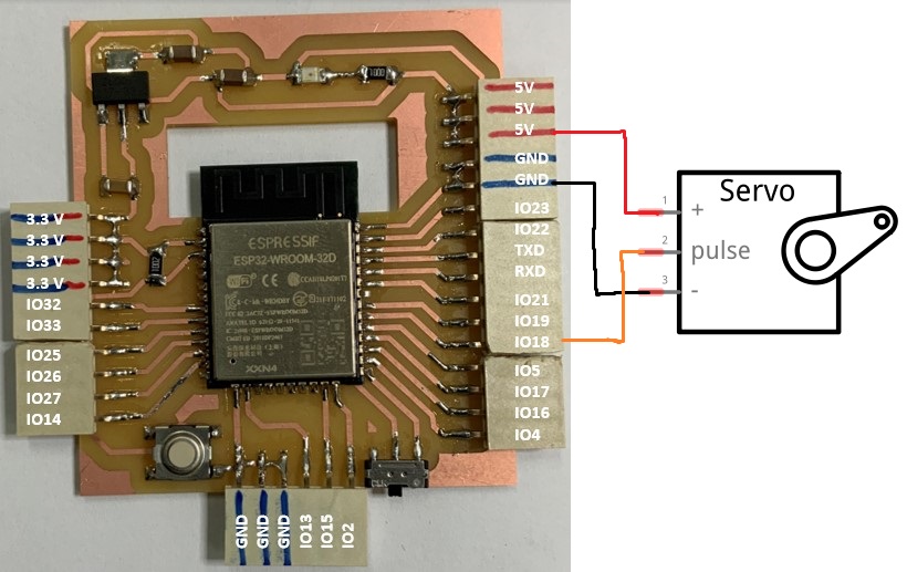
to use the servo-motor we have followed the wiring below.
Since the signal pin of the servo motor must be connected to a PWM pin, we have chosen pin 18. Once the wiring is finished we move on to the programming. For the programming of our circuit board we will use the example program “Sweep” from the library “ESPservo.h”.
#include<ESP32Servo.h>Servomyservo;// create servo object to control a servo// 16 servo objects can be created on the ESP32intpos=0;// variable to store the servo position// Recommended PWM GPIO pins on the ESP32 include 2,4,12-19,21-23,25-27,32-33 // Possible PWM GPIO pins on the ESP32-S2: 0(used by on-board button),1-17,18(used by on-board LED),19-21,26,33-42#if defined(ARDUINO_ESP32S2_DEV)intservoPin=16;#elseintservoPin=18;#endifvoidsetup(){// Allow allocation of all timersESP32PWM::allocateTimer(0);ESP32PWM::allocateTimer(1);ESP32PWM::allocateTimer(2);ESP32PWM::allocateTimer(3);myservo.setPeriodHertz(50);// standard 50 hz servomyservo.attach(servoPin,1000,2000);// attaches the servo on pin 18 to the servo object// using default min/max of 1000us and 2000us// different servos may require different min/max settings// for an accurate 0 to 180 sweep}voidloop(){for(pos=0;pos<=180;pos+=1){// goes from 0 degrees to 180 degrees// in steps of 1 degreemyservo.write(pos);// tell servo to go to position in variable 'pos'delay(15);// waits 15ms for the servo to reach the position}for(pos=180;pos>=0;pos-=1){// goes from 180 degrees to 0 degreesmyservo.write(pos);// tell servo to go to position in variable 'pos'delay(15);// waits 15ms for the servo to reach the position}}
After uploading the code on the card here is the result.
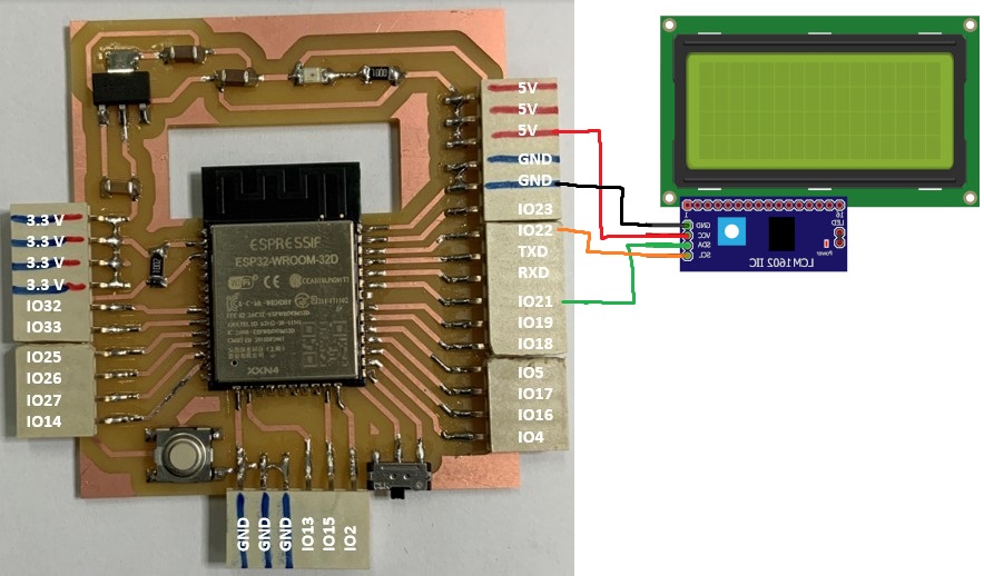
to use the LCD 2004 screen we have followed the wiring below
Indeed, the LCD 2004 with the associated I2C module uses the I2C protocol to communicate with the microcontroller ESP32 or the default pins of the I2C protocol on the ESP32 are GPIO21 and GPIO22. once the wiring is finished we move on to the programming. For the programming of our circuit we have modified the example program “HelloWorld” of the library “LiquidCrystal_I2C.h” as below.
#include<Wire.h>#include<LiquidCrystal_I2C.h>LiquidCrystal_I2Clcd(0x27,20,4);// set the LCD address to 0x27 for a 16 chars and 2 line displayvoidsetup(){lcd.init();// Print a message to the LCD.lcd.backlight();lcd.setCursor(4,0);lcd.print("Hello world!");lcd.setCursor(6,1);lcd.print("Welcome");lcd.setCursor(6,2);lcd.print("to the");lcd.setCursor(1,3);lcd.print("Fab Lab Y'ELLO LAB");}voidloop(){}
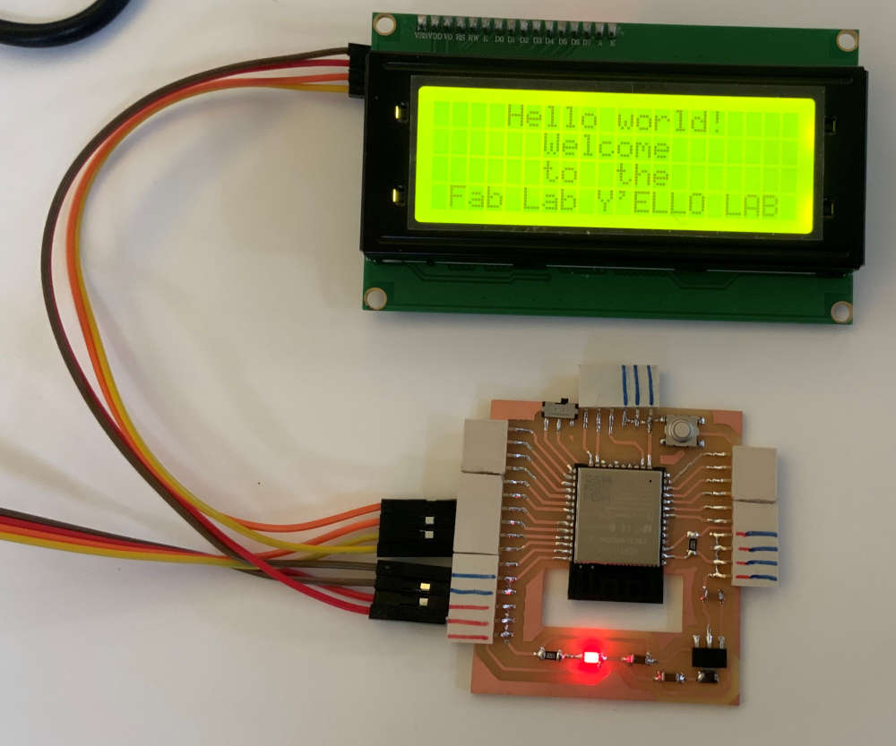
after uploading the code on the card here is the result.