11. Input devices
Group assignment:
-
Probe an input device(s)’s analog and digital signals
-
Document your work on the group work page and reflect on your individual page what you learned
To see our group assignment click here
Individual assignment:
- add a sensor to a microcontroller board that you have designed and read it.
For this week’s assignment, we have chosen to use a rotary encoder module KY-040 with the electronic board we made in Week 8 (Electronics production).
Rotary encoder KY-040
Presentation
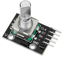
The KY-040 Rotary Encoder is a rotary input device that provides an indication of the degree of knob rotation qnd the direction of rotation. It is an ideal device for controlling stepper motors and servo motors.
Operation
Rotary encoders can rotate 360° without stopping. Inside the encoder is a slotted disc that is connected to pin C, the common ground. It also has two contact pins A and B, as shown below.
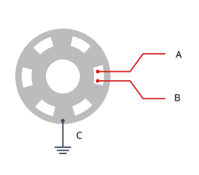
When you turn the knob, A and B make contact with the common ground pin C in a specific order depending on which direction you turn the knob. When they make contact with common ground, two signals are generated. These signals are 90° out of phase because one pin makes contact with common ground before the other. It is referred to as quadrature encoding.

When the knob is turned clockwise, the A pin connects to ground before the B pin. When the knob is turned anticlockwise, the B pin connects to ground before the A pin. By monitoring when each pin connects or disconnects from ground, we can determine the direction in which the knob is being rotated. This can be accomplished by simply observing the state of B when A’s state changes. For more details click here.
Wiring diagram
To use the Rotary encoder KY-040 we have followed the wiring below.
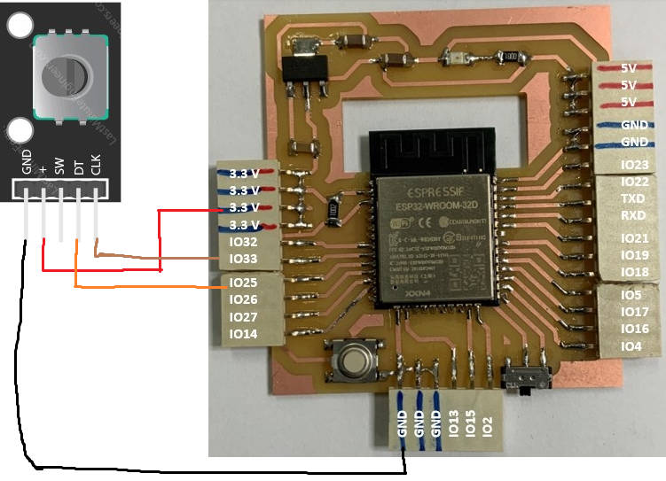
the rotary encoder is powered in 3.3V because we use it with an ESP32. Indeed the GPIO of the ESP32 receive 3.3V in input.
Programming
To program our circuit board with the rotary encoder module, we will use the serial monitor of the arduino IDE to display the value of a number that increments or decrements depending on the direction of rotation of the rotary encoder.