Skip to content

14. Interface and application programming

Group assignment:

  • Compare as many tool options as possible

To see our group assignment click here

Individual assignment:

  • Write an application that interfaces a user with input and/or output device(s) on a board that you made.

For this week’s assignment, we chose to use node red which is a nodejs based solution to develop an interface to communicate with two MCUs namely the ESP01 and the ESP32 presented in Week 13 (Networking and communications).

Indeed, the assignment that will be done is related to our final project. Regarding the operation we will have a RFID reader and an LCD screen connected to the ESP32 and a relay with a led connected to the esp 01. Our interface will allow to turn on or off the relay and to display the code recovered by the RFID reader.

Our work this assignment will be divided into 4 parts: Installation of node-red, wiring and programming the MCU, programming the interface and testing.

Installation of node-red

Node-RED is a programming tool for wiring together hardware devices, APIs and online services in new and interesting ways. It provides a browser-based editor that makes it easy to wire together flows using the wide range of nodes in the palette that can be deployed to its runtime in a single-click. for more details click here

For the installation of node red we will use the raspberry pi used in week 13.

To connect to the raspberry pi with ssh we used windows powershell.

  • connection to the Raspberry pi

1
2
3
4
ssh <username>@<host_ip_address> -P <port_number>

# For example
ssh pi@192.168.1.210 -P 1022
results

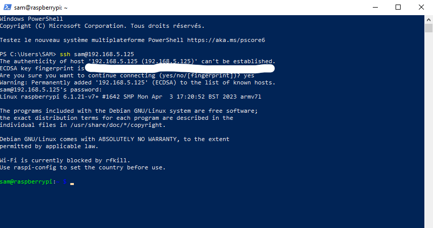
  • now that we are connected to the raspberry pi we will update the pi before any other command.
sudo apt-get update 
sudo apt-get upgrade

bash <(curl -sL https://raw.githubusercontent.com/node-red/linux-installers/master/deb/update-nodejs-and-nodered)

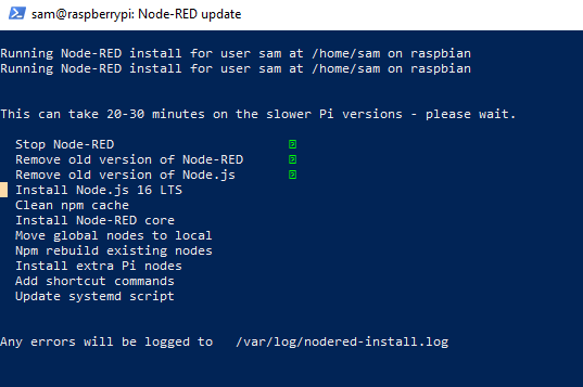
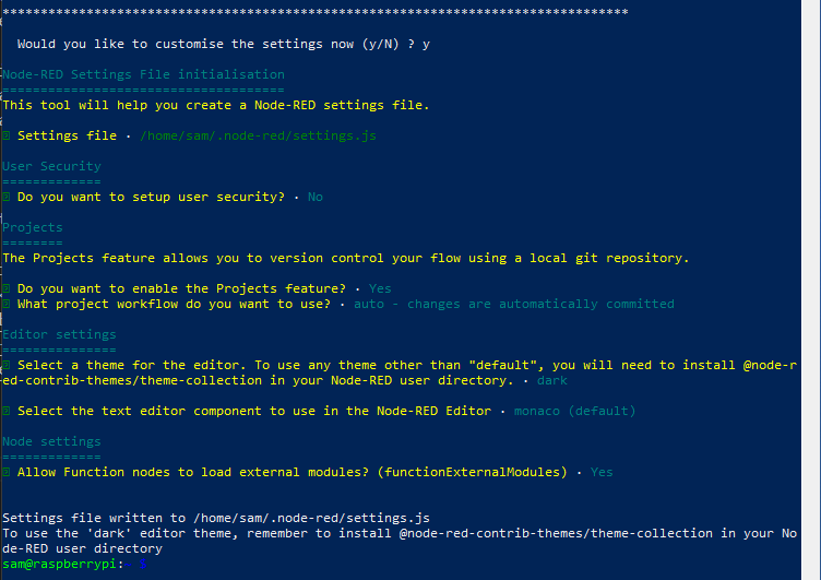
once the installation is finished, we entered the address of our Raspberry pi followed by “:1880” to access the node-red home page.

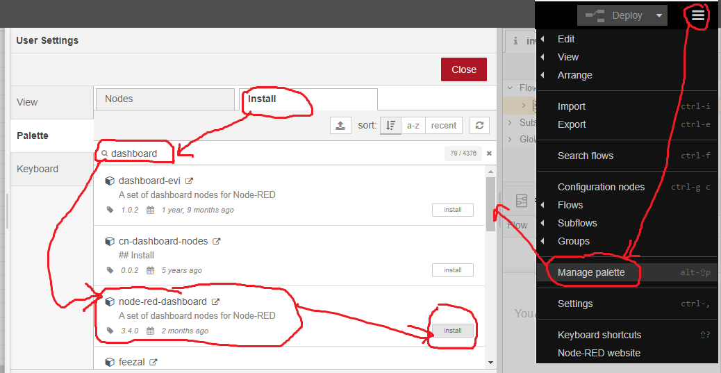
In order to program our interface with node-red we need to install an extension as shown below.

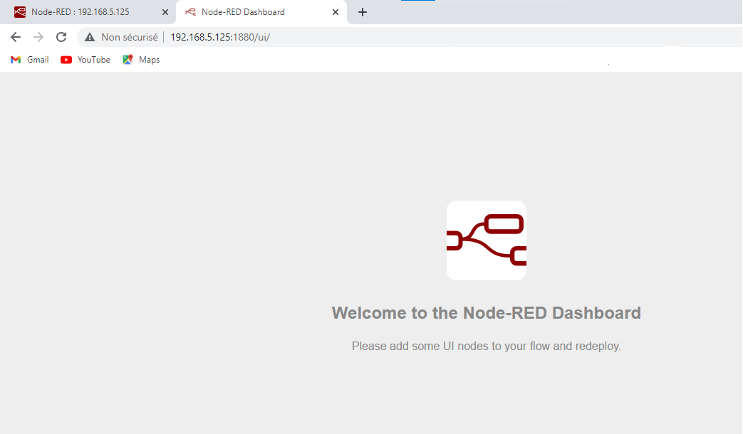
Once the installation is complete you can enter the IP address of the Raspberry followed by “:1880/ui” to access the dashboard.

Wiring and programming the MCU

ESP32

Here is our wiring diagram

For programming we used the Arduino IDE for more details on programming refer to week 9. and to week 13.

ESP32_program.ino
#include <WiFi.h>
#include <PubSubClient.h>
#include <SPI.h>
#include <RFID.h>

// Replace the next variables with your SSID/Password combination
const char* ssid = "REPLACE_WITH_YOUR_SSID";
const char* password = "REPLACE_WITH_YOUR_PASSWORD";

// Add your MQTT Broker IP address, example:
//const char* mqtt_server = "192.168.1.144";
const char* mqtt_server = "YOUR_MQTT_BROKER_IP_ADDRESS";

WiFiClient espClient;
PubSubClient client(espClient);

RFID monModuleRFID(5,18);

#define MSG_BUFFER_SIZE  (50)

char msg[MSG_BUFFER_SIZE];
int UID[5];
String code_rfid ="";

void setup_wifi() {

  delay(10);
  // We start by connecting to a WiFi network
  Serial.println();
  Serial.print("Connecting to ");
  Serial.println(ssid);

  WiFi.mode(WIFI_STA);
  WiFi.begin(ssid, password);

  while (WiFi.status() != WL_CONNECTED) {
    delay(500);
    Serial.print(".");
  }

  randomSeed(micros());

  Serial.println("");
  Serial.println("WiFi connected");
  Serial.println("IP address: ");
  Serial.println(WiFi.localIP());
}

void reconnect() {
  // Loop until we're reconnected
  while (!client.connected()) {
    Serial.print("Attempting MQTT connection...");
    // Create a random client ID
    String clientId = "ESP32Client-";
    clientId += String(random(0xffff), HEX);
    // Attempt to connect
    if (client.connect("ESP32","YOUR_USERNAME","PASSWORD")) {
      Serial.println("connected");
     } else {
      Serial.print("failed, rc=");
      Serial.print(client.state());
      Serial.println(" try again in 5 seconds");
      // Wait 5 seconds before retrying
      delay(5000);
    }
  }
}

void setup() {
  Serial.begin(115200);
  setup_wifi();
  client.setServer(mqtt_server, 1883);
  SPI.begin();
  monModuleRFID.init();
}

void loop() {

  if (!client.connected()) {
    reconnect();
  }
  client.loop();

 last_rfid();

}

void last_rfid() {
  if (monModuleRFID.isCard()) {  
    if (monModuleRFID.readCardSerial()) {        
     for(int i=0;i<=4;i++)
      {
        UID[i]=monModuleRFID.serNum[i];  
      }

     }

    code_rfid = UID[0];
    code_rfid += UID[1];
    code_rfid += UID[2];
    code_rfid += UID[3];
    code_rfid += UID[4]; 

    const char* val =code_rfid.c_str();
    snprintf (msg, MSG_BUFFER_SIZE, "%s",val);
    client.publish("ID_USER", msg);
    Serial.println(msg);

   }       
    monModuleRFID.halt();

    delay(1); 
    code_rfid ="";
 }

ESP01

For programming we used the Arduino IDE for more details on programming refer to week 13.

ESP01_program.ino
#include <ESP8266WiFi.h>
#include <PubSubClient.h>

#define relayPin 0     // the number of the relay pin
#define ledPin  2    // the number of the LED pin

// Update these with values suitable for your network.

const char* ssid = "........";
const char* password = "........";
const char* mqtt_server = ".....";

WiFiClient espClient;
PubSubClient client(espClient);


void setup_wifi() {

  delay(10);
  // We start by connecting to a WiFi network
  Serial.println();
  Serial.print("Connecting to ");
  Serial.println(ssid);

  WiFi.mode(WIFI_STA);
  WiFi.begin(ssid, password);

  while (WiFi.status() != WL_CONNECTED) {
    delay(500);
    Serial.print(".");
  }

  randomSeed(micros());

  Serial.println("");
  Serial.println("WiFi connected");
  Serial.println("IP address: ");
  Serial.println(WiFi.localIP());
}

void callback(char* topic, byte* payload, unsigned int length) {
  Serial.print("Message arrived [");
  Serial.print(topic);
  Serial.print("] ");
  for (int i = 0; i < length; i++) {
    Serial.print((char)payload[i]);
  }
  Serial.println();


  if ((char)payload[0] == '0') {
    digitalWrite(ledPin, LOW);   // Turn the LED on 
  } 
  else if  ((char)payload[0] == '1')
  {
    digitalWrite(ledPin, HIGH);  // Turn the LED off 
  }
  else if  ((char)payload[0] == '2')
  {
    digitalWrite(relayPin, HIGH);  // Turn the LED off 
  }
  else if  ((char)payload[0] == '3')
  {
    digitalWrite(relayPin, LOW);  // Turn the LED off 
  }

}

void reconnect() {
  // Loop until we're reconnected
  while (!client.connected()) {
    Serial.print("Attempting MQTT connection...");
    // Create a random client ID
    String clientId = "ESP8266Client-";
    clientId += String(random(0xffff), HEX);
    // Attempt to connect
    if (client.connect("ESP82","YOUR_USERNAME","PASSWORD")) {
      Serial.println("connected");
      client.subscribe("cmd_mpass");
    } else {
      Serial.print("failed, rc=");
      Serial.print(client.state());
      Serial.println(" try again in 5 seconds");
      // Wait 5 seconds before retrying
      delay(5000);
    }
  }
}

void setup() {
  Serial.begin(115200);
  pinMode(relayPin, OUTPUT); 
  pinMode(ledPin, OUTPUT);
  setup_wifi();
  client.setServer(mqtt_server, 1883);
  client.setCallback(callback);
}

void loop() {

  if (!client.connected()) {
    reconnect();
  }
  client.loop();
}

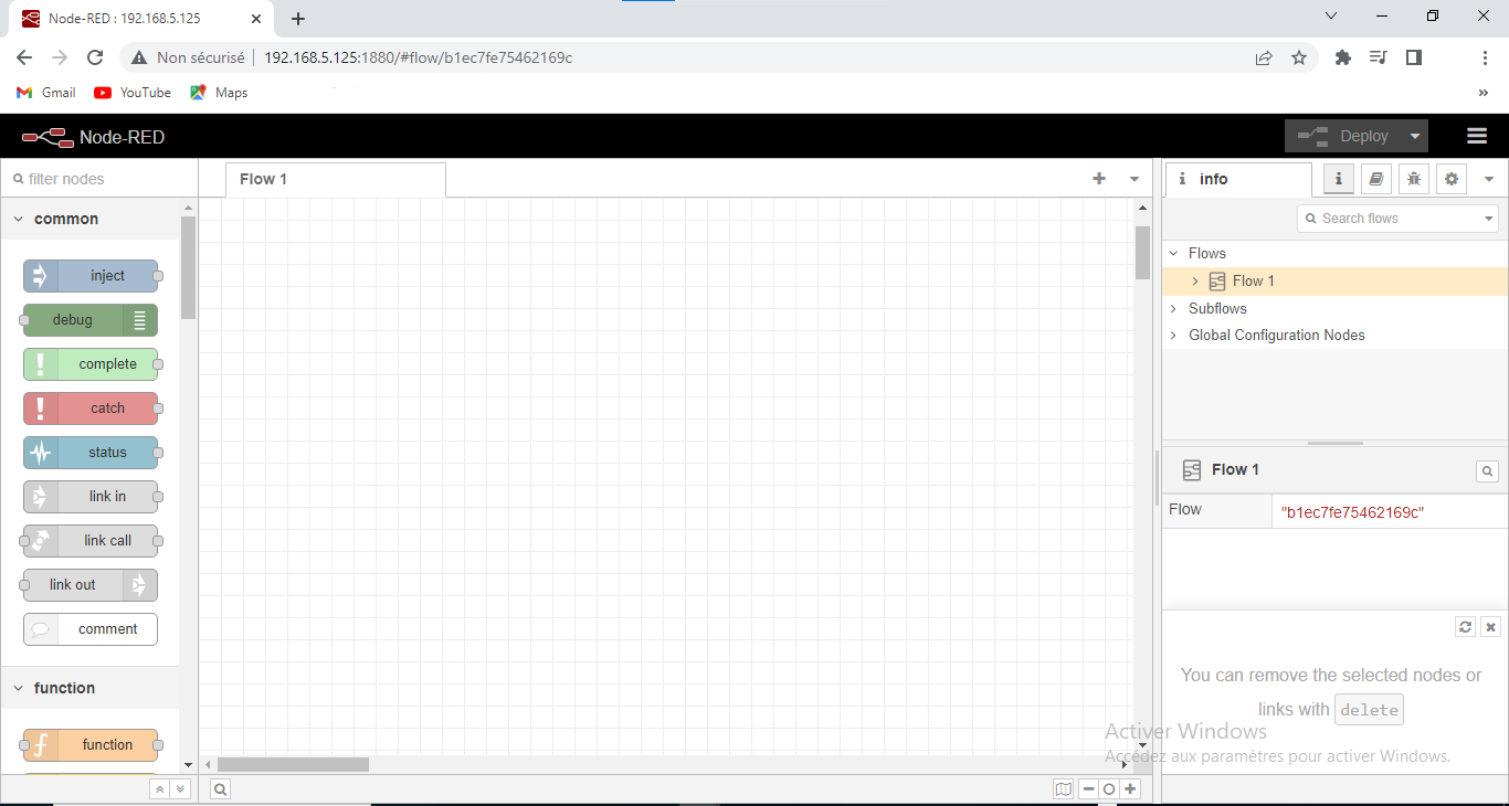
Programming the interface of Node-Red

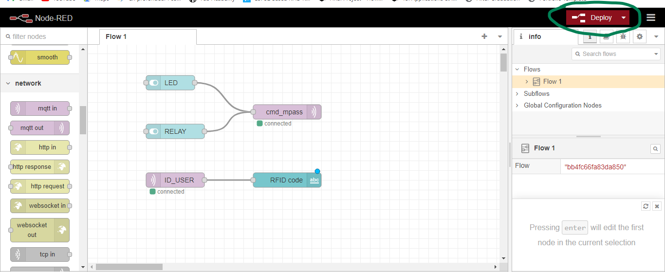
For the programming of the node red interface we will use two switches, one to control the relay and the other to control the led on the ESP01 card. For the visualization of the RFID code retrieved by the ESP32 we will use an input field to display it.

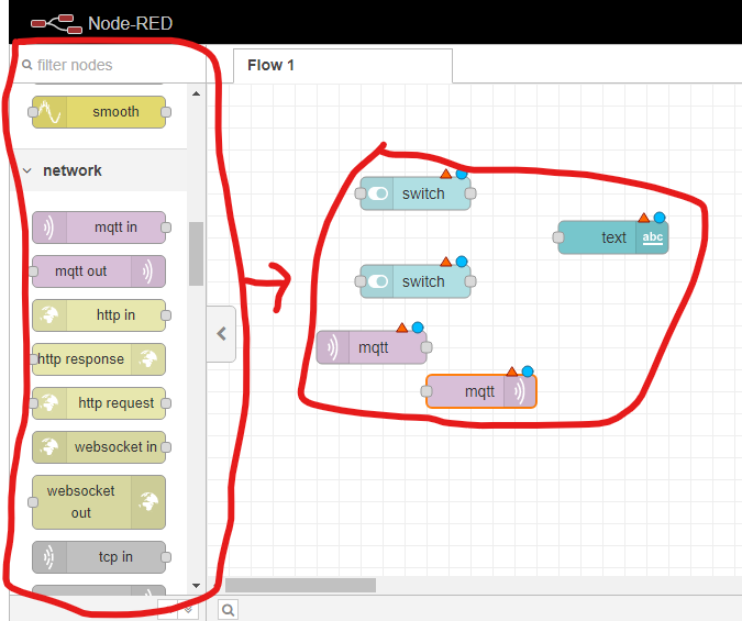
  • We chose the modules we were interested in from the palette on the left of the screen and made a click and drag as shown below.

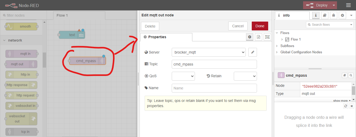
  • In order to set the different nodes, double click on them and the settings window will appear as shown below.

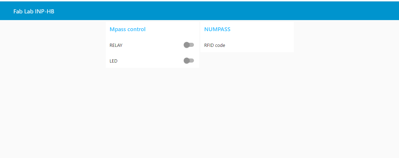
  • once the nodes are set up we click on deploy and we should have the following result

  • Now we can visualize our interface by entering the IP address of the raspberry pi followed by “:1880/ui”. Here is our interface.

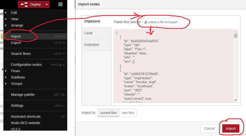
I know more than one person is wondering but how to reproduce the interface don’t worry you just need to download my source file and go to the node red menu and click on import as shown below.

Testing

Below you will find our hero video. I hope our work will inspire you to do extraordinary things.

Files


Last update: May 26, 2023