15. Wildcard week
Group assignment:
None
Individual assignment:
Design and produce something with a digital fabrication process (incorporating computer-aided design and manufacturing) not covered in another assignment, documenting the requirements that your assignment meets, and including everything necessary to reproduce it.
For this week’s work, we’ve chosen to use a plasma cutter to cut out the map of our country, Côte d’Ivoire, as a decorative object.
Our work will be divided into 4 parts: Presentation of the Plasma cutter in our Fab Lab, design of our model, generation of the cutting path and, finally, plasma cutting.
Presentation of the Plasma cutter in our Fab Lab
Presentation
A plasma cutter is a controlled machine that uses plasma cutting technology to cut all conductive materials. A plasma arc is formed when a gas, such as oxygen, nitrogen, argon or compressed air, is forced through the nozzle orifice. An electric arc generated by an external power source is then introduced to this high-pressure gas stream, more commonly known as a “plasma jet”. The plasma immediately reaches temperatures of up to 22,000°C, enabling it to cut very quickly. The role of the plasma cutter is to cut sheet metal quickly and relatively precisely, and to produce different shapes. Plasma can be used to cut metal sheets in thicknesses ranging from 0 to 160 mm, with a precision of plus or minus 0.2 mm.
In our Fab Lab, we have a model HTP-1530 from HITECCNC compressed-air plasma generator up to 168A.
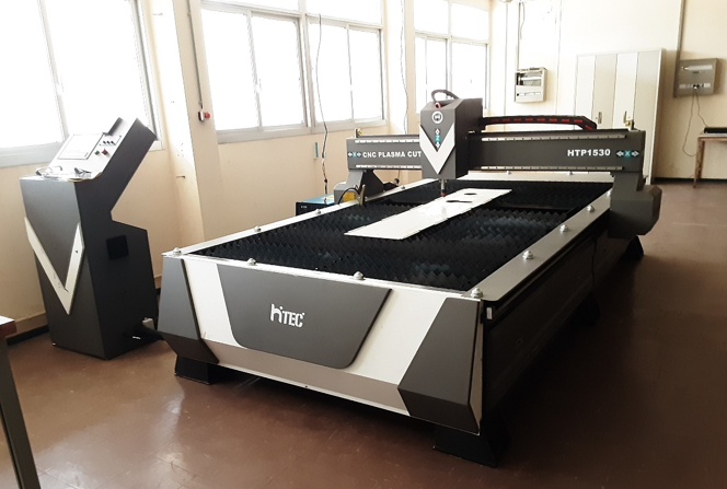
for the operation of the machine we have other additional devices:
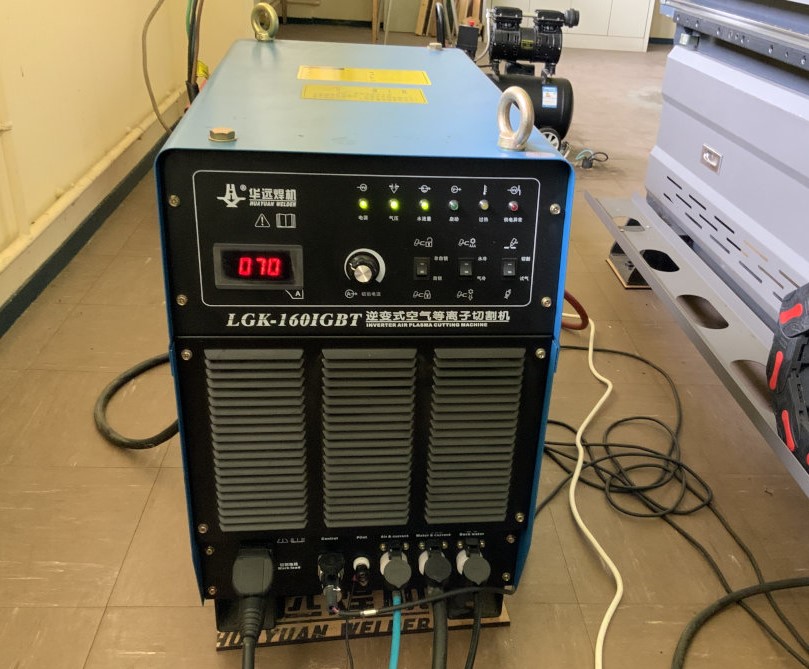
- A Huayuan LGK-160IGBT plasma source.
- Air compressor
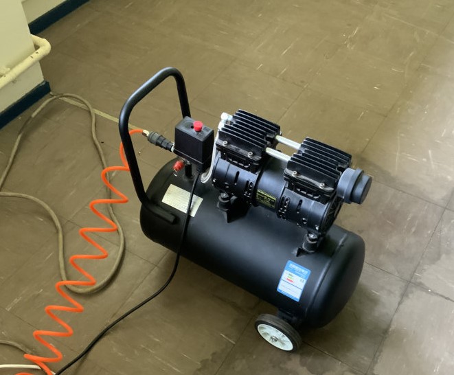
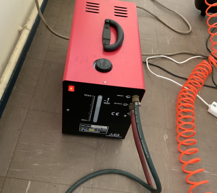
- Water pump station
Specification
| Brand | Hiteccnc HTP-1530 |
|---|---|
| Working area | 1500x3000mm |
| Power supply | Huayuan 160A |
| Control system | CNC Starfire Control system with HYD Independent THC |
| Software | StarCAM |
| Resolution | ± 0.03mm |
| Command | G code (uoo,nc,mmg,plt) |
| Voltage | 380V, 3 phase,50/60HZ |
| Consumble Parts | Cutting nozzle and electrode |
| Max working speed | 0-10000mm/min |
| Motor and driver | Leadshine stepper motor and driver |
Design
To design the geographical map of our country, we first uploaded a map image as shown below.
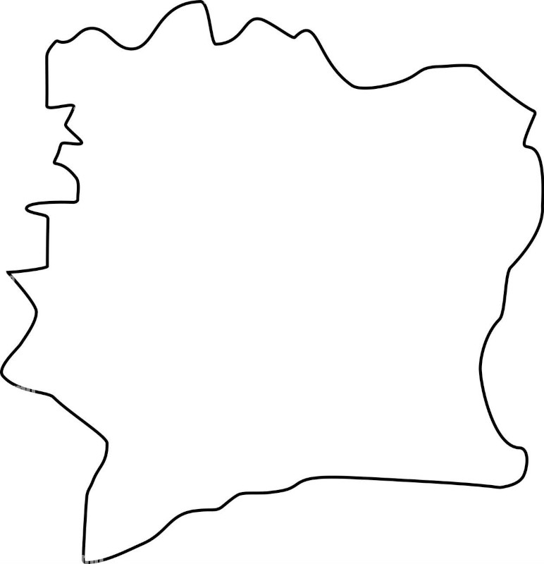
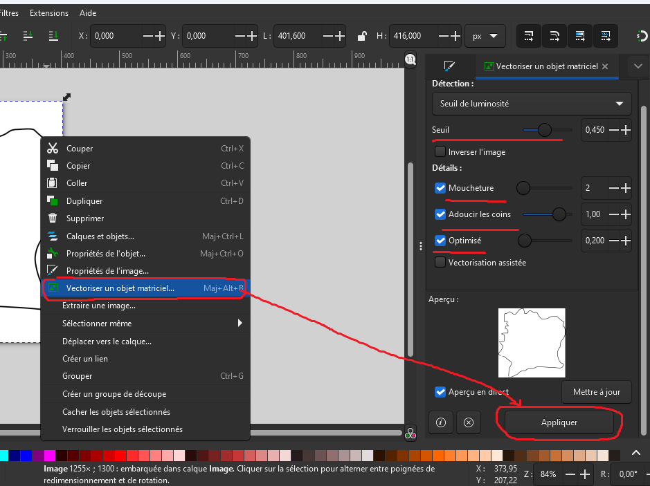
- Once the image was downloaded we opened it with Inkscape to vectorize it as shown below. For more details on Inkscape refer to Week 2 (Computer Aided design).
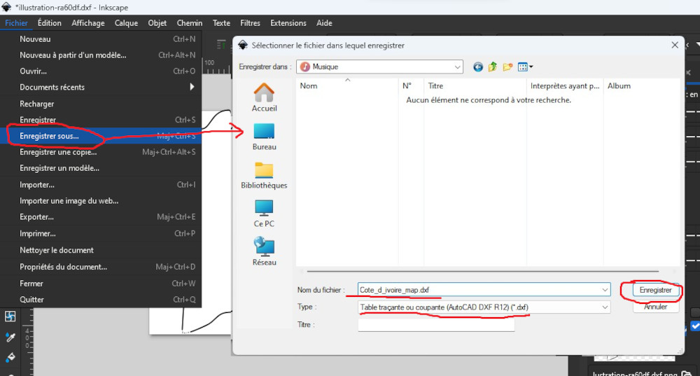
- After vectorizing the image, we exported it in dxf format as shown below.
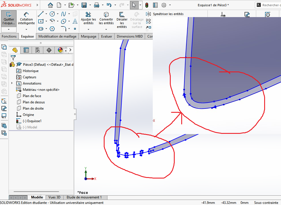
- Once the dxf file had been saved, we opened it with SolidWorks to correct certain openings in the drawing, as shown below.
- To complete the correction, we extruded the drawing as shown below.
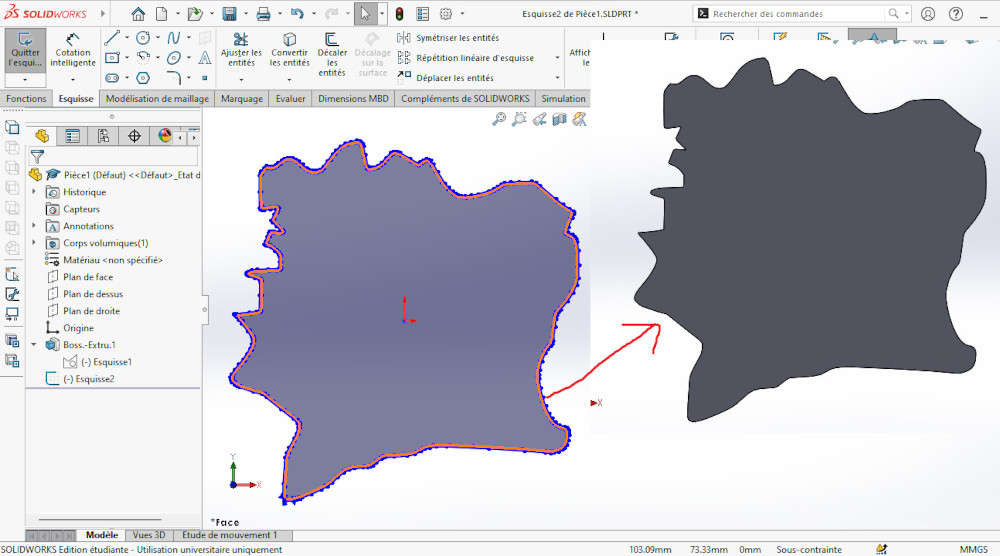
- Now that we have a correct piece with the contours of our country’s map, we’ve made a final export in dxf as shown below.
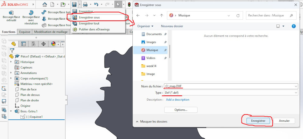
We’ve finished with the design and can now move on to generating the cutting path. To download the dxf file click here.
Cutting path generation
To generate the cutting path, we used the StarCAM software supplied with the machine.
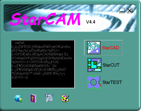
- First we open the software and click on StarCAD.
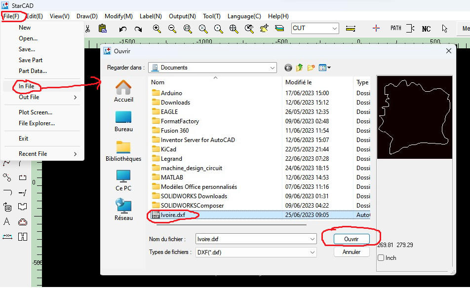
- Once StarCAD was open, we imported our DXF file as shown below
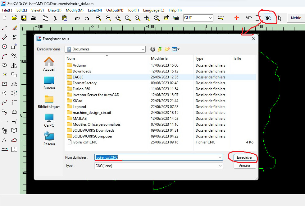
- Click on “Path” to generate the cutting path
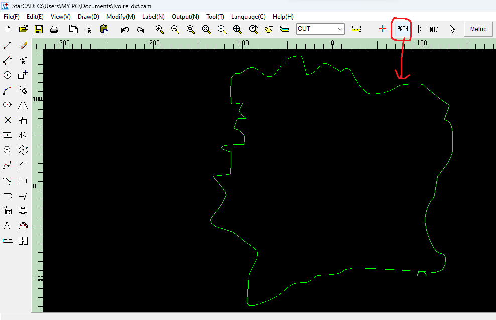
- click on “NC” to save it as shown below.
Once the cutting path has been generated, we move on to cutting. 😊😊😊
Cutting
Before starting any work on the machine, we first had to determine the machine settings, i.e. arc current, arc voltage, cutting speed and the appropriate cutting nozzle. To do this, we referred to the table below, supplied by the manufacturer, which defines all the above parameters as a function of the thickness of the material to be cut.
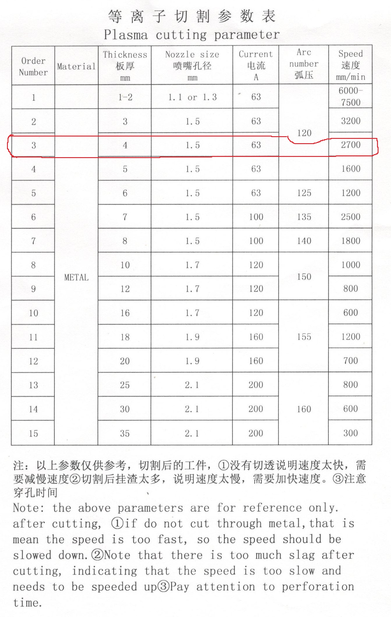
Given that our material is 4 mm thick, here are the parameters we have selected.
Cutting parameter
| Materiel | Metal |
|---|---|
| Thickness (mm) | 4 |
| Nozze size (mm) | 1.5 |
| Current (A) | 63 |
| Arc number | 120 |
| Speed (mm/min) | 2700 |
To start cutting we proceed as follows:
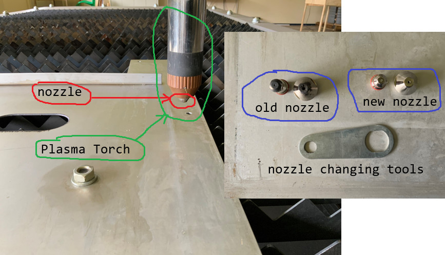
- First, we changed the nozzle as shown below
-
switch on plasma source, air compressor and water pumping station.
-
we set the plasma source to 63A as recommended above
-
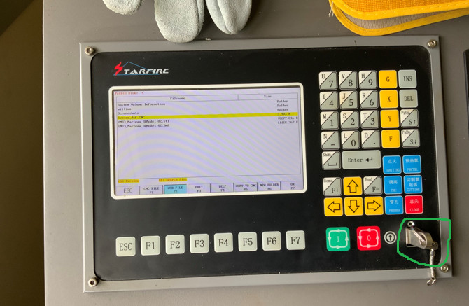
we inserted the USB key containing the cutting file into the plasma cutter’s control panel as shown below
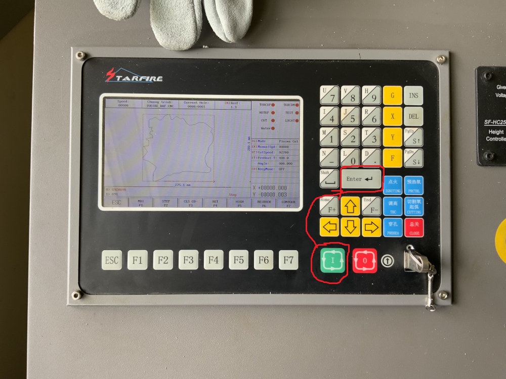
- we correctly positioned the plasma torch using the direction buttons as shown below
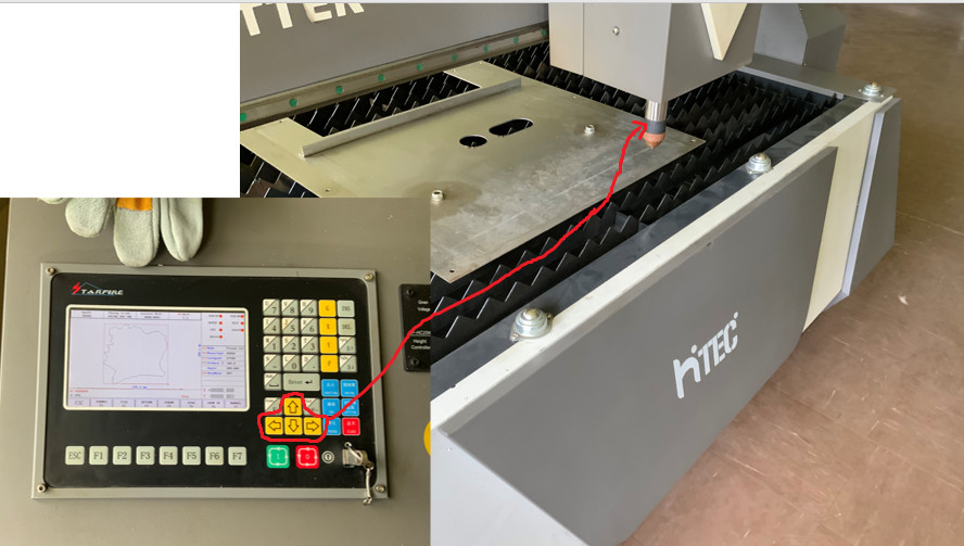
- Finally, we launched the cutting process with the green button as shown below and then pressed the “enter” button.
- Here’s a video of the cut
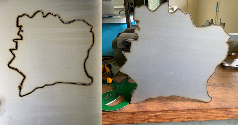
- The final result is
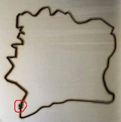
Conclusion
During this week we’ve learned how to use a plasma cutter. we’ve learned that the fundamental principle of a plasma cutter is to generate plasma using an electric arc and water, and then using air to expel the plasma, which falls into a tank to create the cut. and one of the most important points to note is that cutting never starts on the cutting path, because to start cutting with plasma, a large hole is created before cutting begins. as you can see below, the shape circled in red avoids starting holes on the useful part of the part.