8. Electronics production
Group assignment:
-
Characterize the design rules for your in-house PCB production process: document feeds, speeds, plunge rate, depth of cut (traces and outline) and tooling.
-
extra credit: send a PCB out to a board house
-
Document your work to the group work page and reflect on your individual page what you learned
To see our group assignment click here
Individual assignment:
-
Make and test the development board that you designed to interact and communicate with an embedded microcontroller
-
extra credit: make it with another process
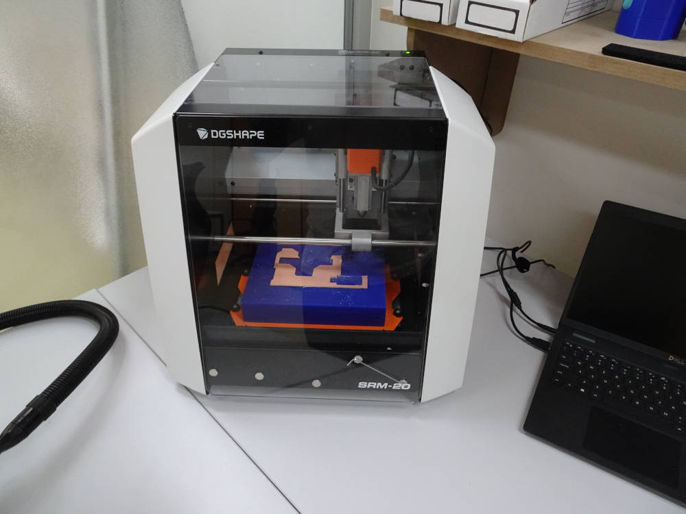
For the realization of this week’s assignment which is the fabrication of an electronic circuit we used the Roland SRM-20 milling machine available in our Fab Lab. For the choice of the printed circuit we will use the printed circuit that we designed in Week 6 (Electronics design).
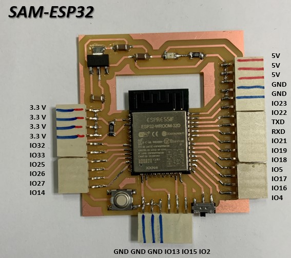
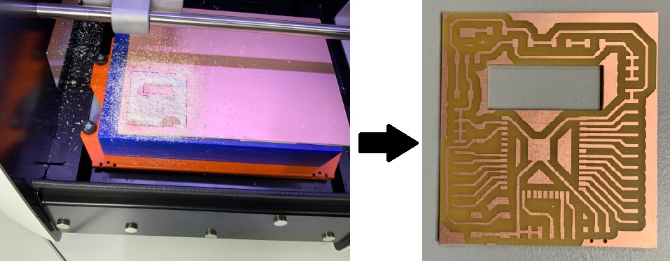
At the end of our work we must obtain the following results
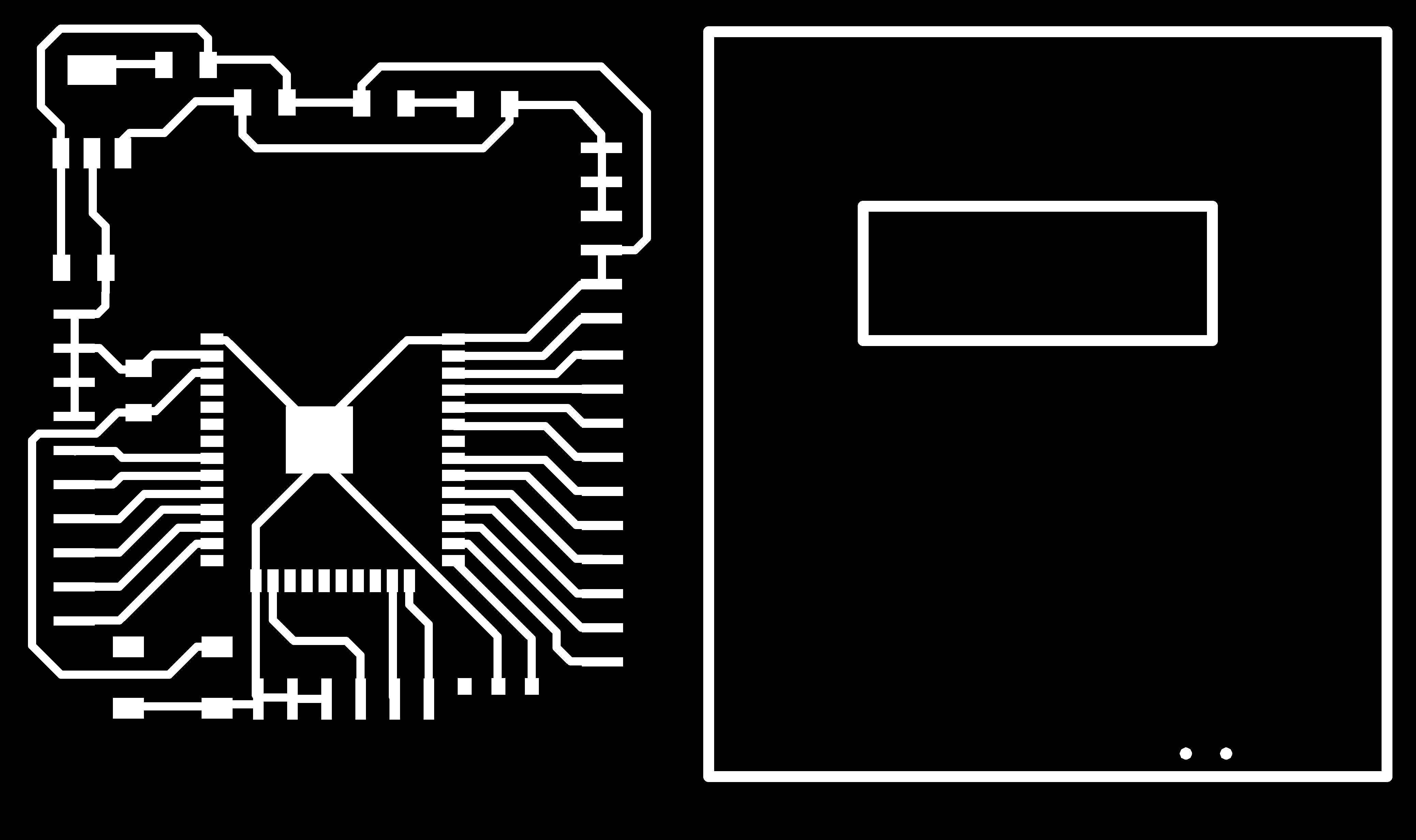
For the manufacture of our circuit we started by recovering the .PNG files of the traces and the contours of our circuit as indicated below.
Click here to download the PNG files.
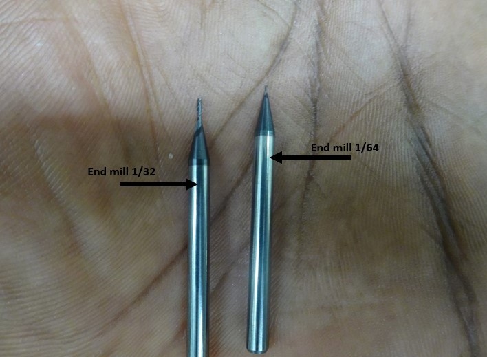
Before we start making our circuit we must first generate the toolpaths for the traces and contours of our circuit. To do this we will use two tools namely : a flat end mill of diameter 1/64 inch for the traces of our circuit and a flat end mill of diameter 1/32 inch for the contour of our circuit.
Generation of the tool path
For the generation of toolpaths we have several solutions at our disposal: the use of Vcarve, FlatCAM, mods CE …
For the choice of our solution we chose mods CE because it is an open-source solution and was designed taking into account the tools we have in our Fab Lab.
Uses of mods CE
Mods is an online tool developed by Niel’s Center for Bits and Atoms used to convert image files to milling files.
For more information on mods click here.
-
Access to mods by clicking on the link mods CE.
-
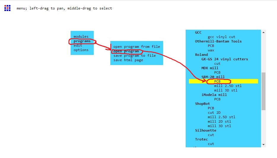
Once on the CE mods page make a right click on your mouse in the white part as shown below. select “programs>open program>SRM-20 mill>PCB” you should have the display below.
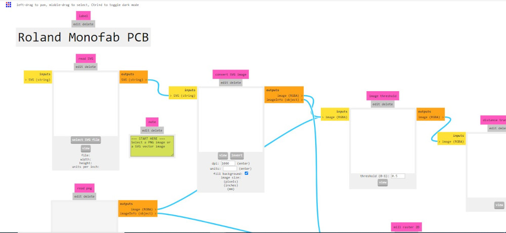
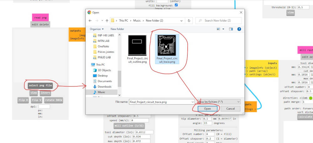
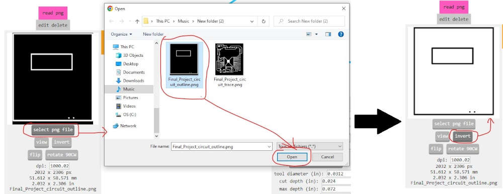
- Go to the “read png” module and click on “select png file” select the png file of the circuit traces as shown below and click on “Open”.
Now that we have imported the image of the traces of our circuit we will proceed to the parameterization of Mods for the generation of the G-code for the Roland SMR-20 milling machine.
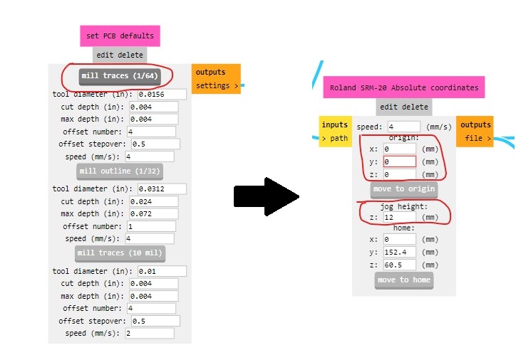
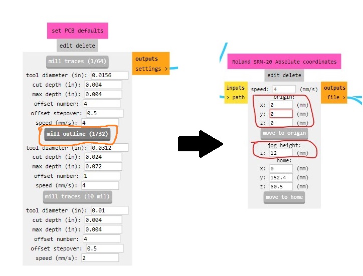
- To do this we first go to the module “set PCB defaults” where we click on “mill traces (1/64)” to choose the cutting parameters of the tools we have selected.
Then we go to the module “Roland SRM-20 Absolute coordinates” where we enter the value 0 for the fields x,y and z so that the tool starts machining at the coordinates (0,0,0) that we have set on the machine and the value 12 for jog height.
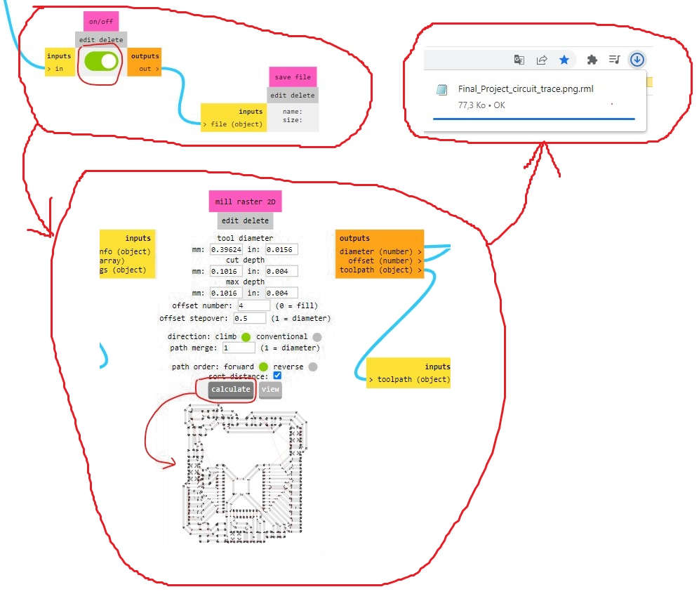
- Once these settings are complete, go to the “on/off” module and link to the “save file” module as shown below. Switch the module to “on” so that we can download the cutting file once its generation is complete. To generate the G-code file go to the “mill raster 2D” module and click on “calculate” a “.rml” file should download automatically as shown below.
- Now that we finished with the traces of the circuit we move to the contours of the circuit to do this go to the module “red png” click on “select png file” and chose the image of the contour as shown below. it should be known that the algorithm of mods in the generation of toolpaths considers the black areas of the image as the areas to be machined. so that mods can correctly generated the toolpath for the contours of our ciruit we click on “invert” in the module “read png” as shown below.
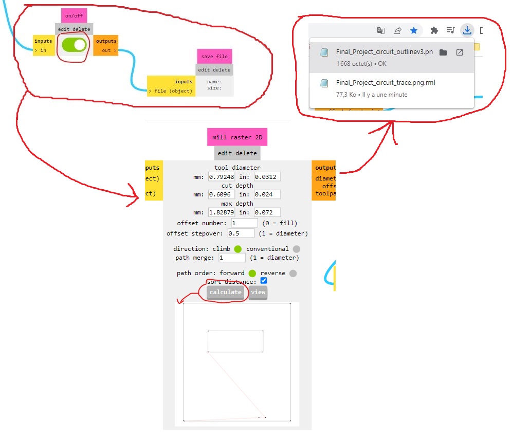
- We move to the setting of the tool, go to the module “set PCB defaults” click on “mill outline (1/32)” to choose the cutting parameters of the tool for cutting the outline of our circuit.
- To generate the G-code for the Roland SRM-20 milling machine follow the same procedure as for the circuit traces.
Now that we have finished generating the G-codes for the toolpaths we can move on to the machining of our electronic circuit.
Machining of our electronic circuit
For the machining of our electronic circuit we followed the tutorial of the Fab Academy. For a better understanding of the machining procedure of the circuit we have broken it down into several steps namely :
Step 1: Preparation of the machine
- Turn on the Roland SRM-20 milling machine, connect it to your computer, and open the VPanel software for SRM-20. A good tip is to warm up the spindle for 10 minutes at half speed before using it. To do this, move the gauge in the “Spindle Spend” module to the middle as shown below, click on “ON” in “Spindle” and wait 10 minutes.
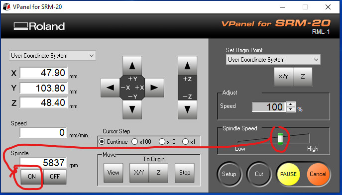
- After the 10 minutes click on “OFF”, now we go to the assembly of the circuit board as shown below.
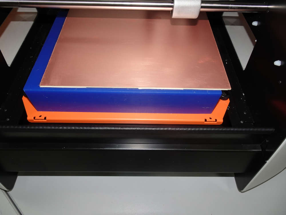
- Since we start by machining the traces of our circuit we will mount the end mill 1/64 inch.
Be careful that the tool doesn’t fall off or it will break and that will be a shame.
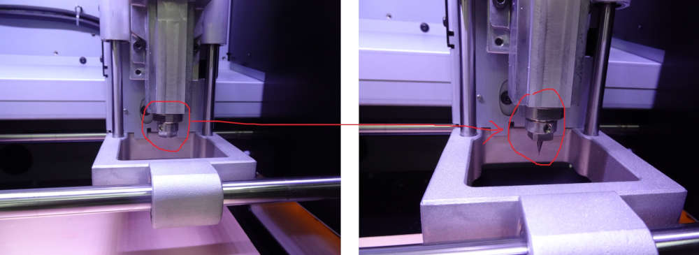
Once the tool is mounted, we move on to the definition of the X, Y and Z axis zero.
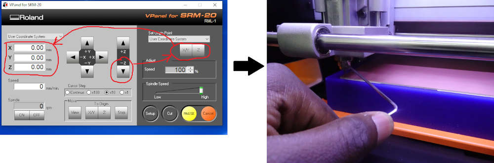
Step 2: Definition of the X, Y and Z axis zero.
- First we start with the X and Y axes. We use the buttons Y+; Y-; X+ and X- to move the X and Y axes to the original position we want.
Note that the (0,0) of the file we created with mods is in the lower left corner.
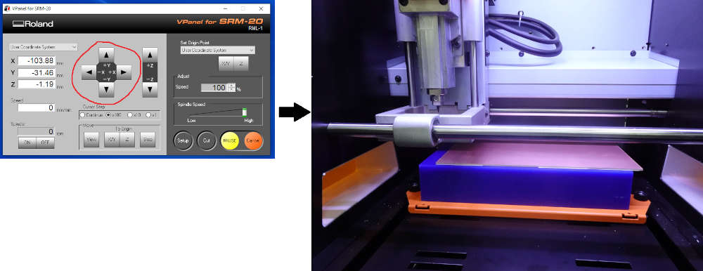
- For the origin of Z we click on the “Z-” button until we are close to the plate, then we click on the X/Y and Z buttons in the “Set Origin Point” area and we loosen the endmill so that it falls on the surface of the board and we tighten the endmill.
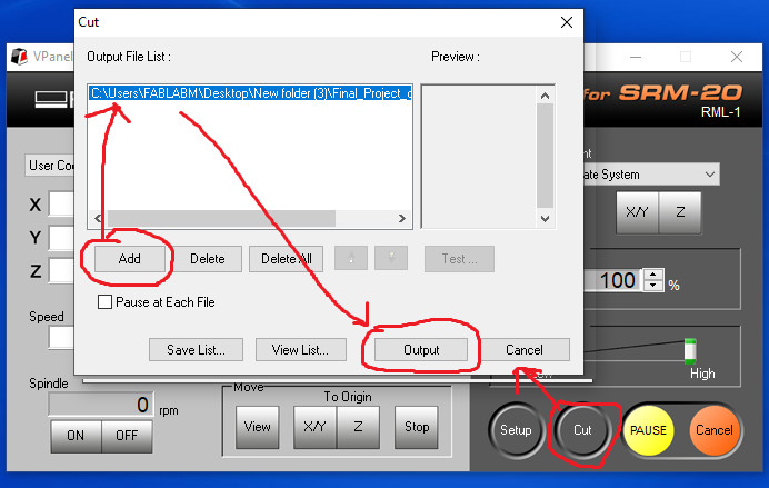
Step 3: Cutting out the circuit board traces
- to machine the circuit board traces, click on “cut” in Vpanel and select the trace file generated by mods as shown below and launch the machining by clicking on output.
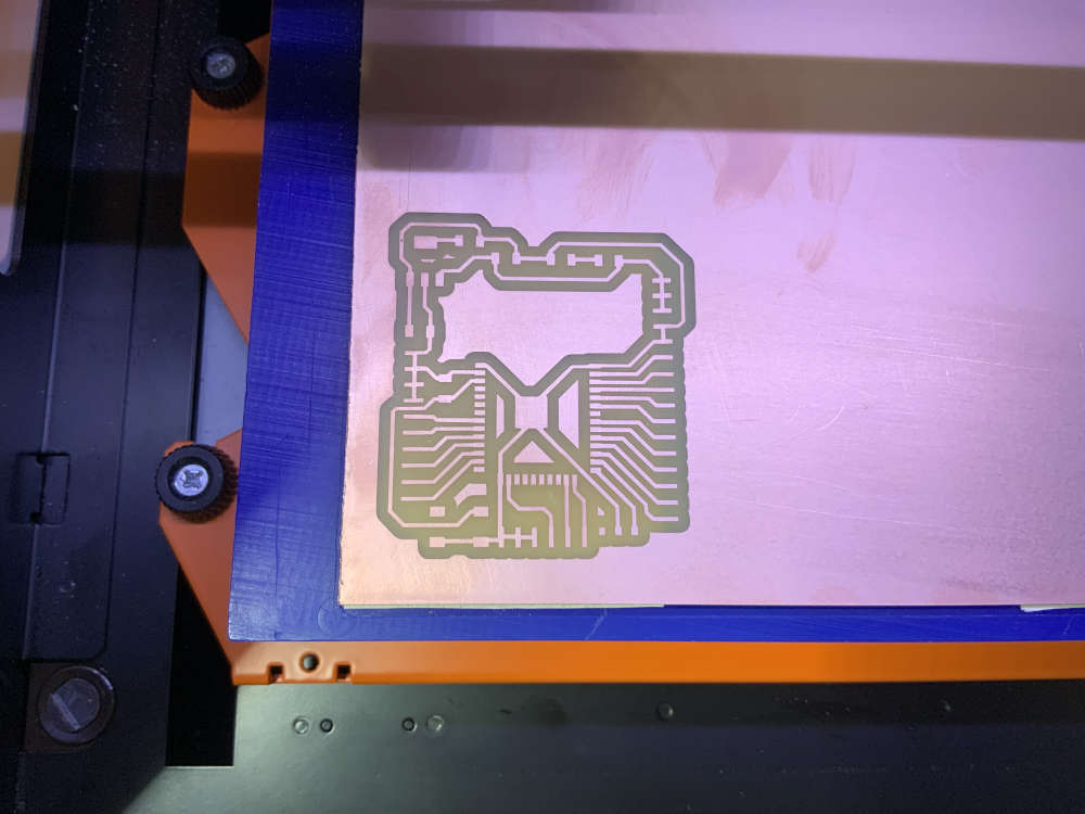
- We obtained the following results after 45 minutes of machining.
- Once the traces of the circuit board are finished we move on to the machining of the circuit board outline. To do this we change tools using endmill 1/32 inch. Once mounted we take the origin of the Z axis before starting the machining.
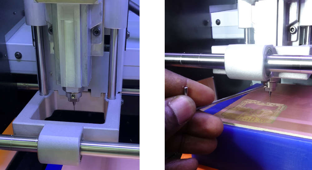
- After 6 minutes of machining we obtained the following results.
After having finished the manufacture of our circuit board we pass to the soldering of the different components on the circuit board.
Soldering of components on the circuit board
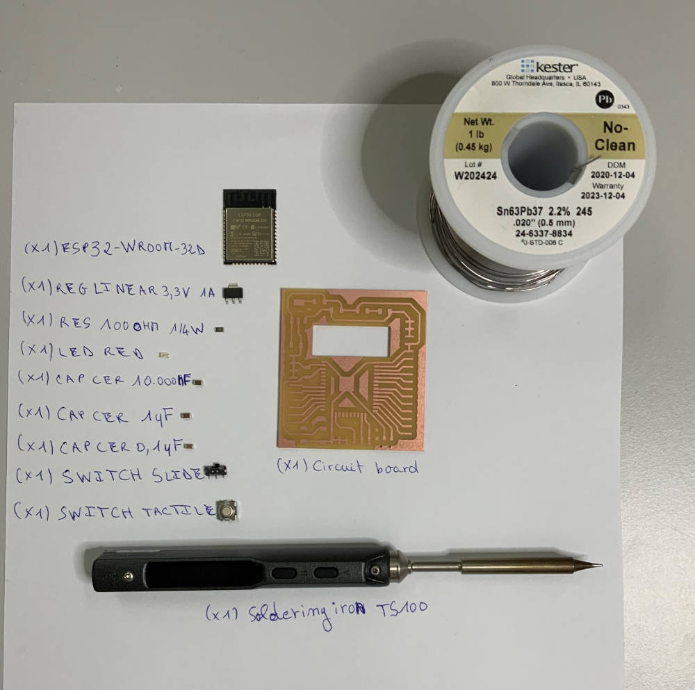
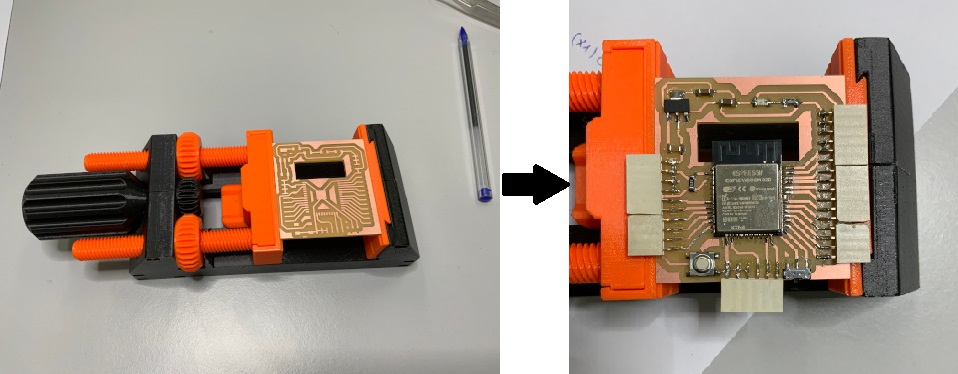
To solder the different electronic components to our circuit we have put them all together as shown below to make the task easier.
After 1 hour of soldering here are the results we obtained. 😊
After having finished soldering the components on our circuit board we move on to test our circuit board.
Test of our ciruit board
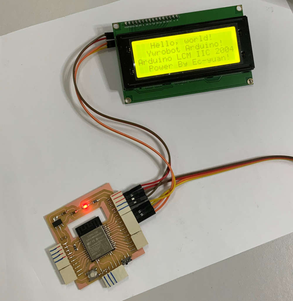
To test our circuit board we programmed it with IDE Arduino to display characters on an LCD screen.
For the program we used the example program “HelloWorld” from the library “LiquidCrystal_I2C.h”
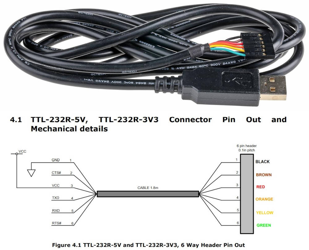
For uploading the program to our circuit we used a TTL-232R-5V cable which allows to convert USB to UART. To connect it to our board we followed the description of the pins below from the data sheet.
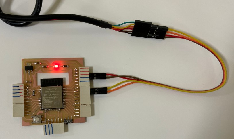
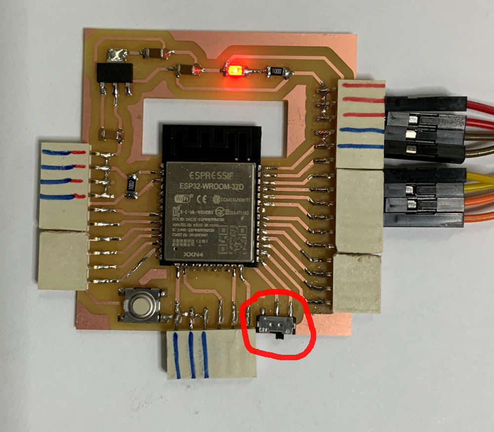
To be able to upload a program on our circuit, it is necessary that the ESP32 microcontroller is in Boot mode. To do this, we have to activate the switch on the circuit as shown below, in fact the switch allows to connect the IO0 input of the ESP32 to GND.
Here is the final result we can confirm that our electronic circuit board works. !!!YOUPI 😊
For this week we made a little video of our work.