Final Project
The Problem
Do you know the PID controller?, maybe yes, maybe no. It isn’t complicated to understand and it’s used for many things. SPOILER!, the 3D printers use it.
Do you remember when you wanted to learn something that you didn’t understand in class?… Surely, you’re looking for help on the internet, there is a lot of information there such as explanatory videos or tutorials.
When students begin to learn about controllers, they need learning and experimentation modules. The equipment for this purpose can be grouped into two types, training modules and didactic modules.
Training modules
- Require intermediate technical level.
- They are expensive.
- Slow changes, with delay.
- allow experimenting with different conditions.
Teaching modules
- They are cheaper.
- They are easy to understand, replicate and manufacture.
- don’t allow experimenting with different conditions.
My idea is to take a didactic system and implement an HMI, so that a student can experiment and learn with a module that combines technical and professional experience with the ease of replicating and manufacturing of the didactic modules.
Research
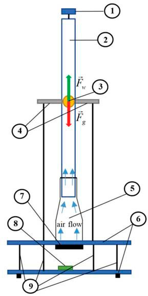
The first step is to find a system that allows me to achieve my goal. I opted for a air levitation system. This system can be controlled with a PID controller, it doesn’t present delays and visually appealing.
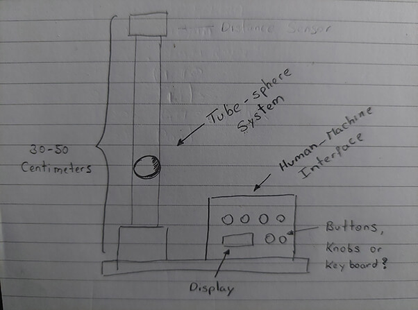
My initial sketch
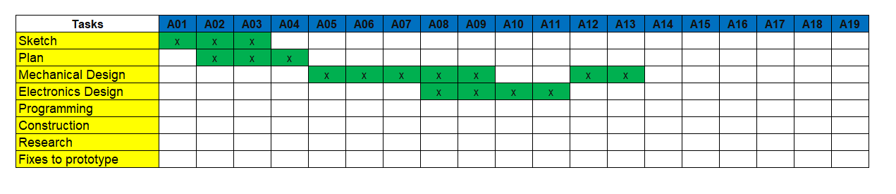
Schudule
Structure design
With the initial sketch, go on to design the module, to complete the design, review the manufacturing techniques such as: 3D printing and laser cutting.
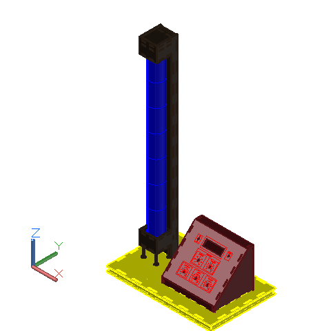
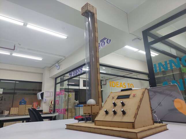
The first part is the base, it has an area of 40 x 25cm
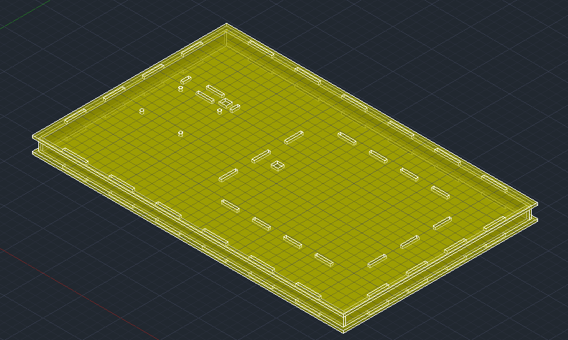
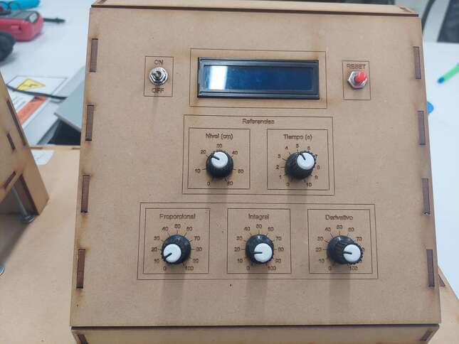
On this base is the HMI module
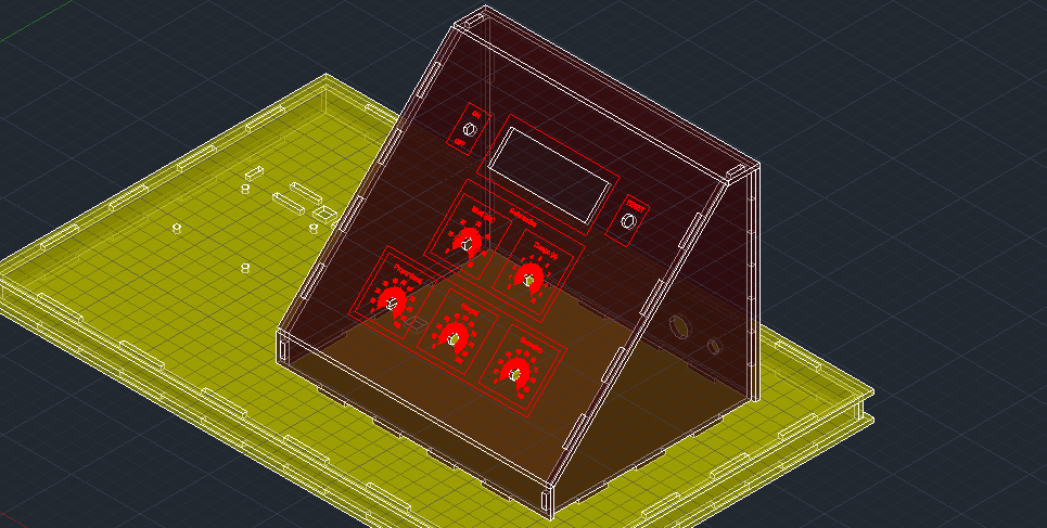
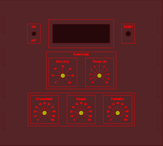
The HMI has an on-off switch, a reset button, and 3 potentiometers for the PID control variables, one for reference and one for time, it also has a 16x2 LC display to view the data.
At the base there is also the tube-sphere system, at the bottom there will be a fan that will drive the sphere along the tube.
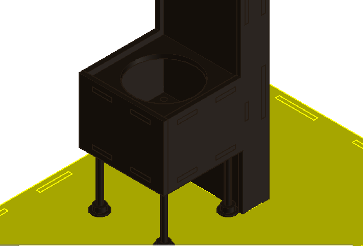
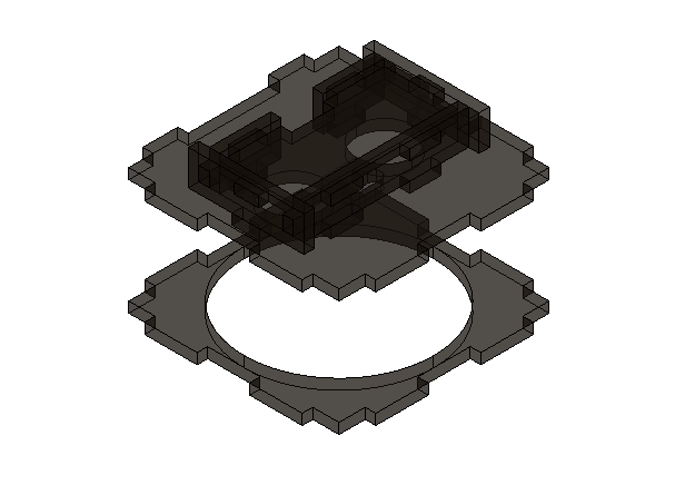
And in the upper part there will be an ultrasonic sensor, to measure the height of the sphere.
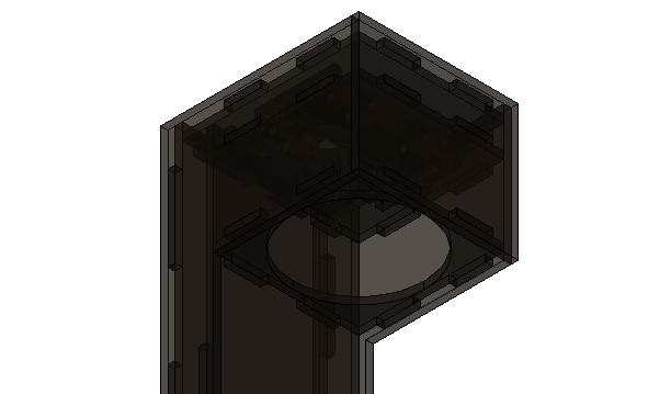
This part has an internal structure so that the ultrasonic sensor is not moved by the air that drives the fan from below, or when the sphere reaches the top.
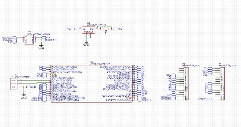
Electronic Design
Another important part of the project is the electronics, as always use EasyEDA.
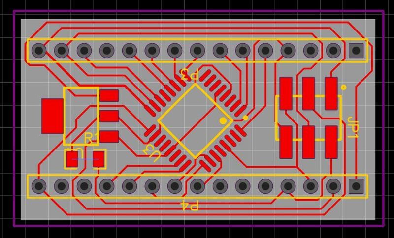
then, we go on to manufacture our PCB, and put the components,
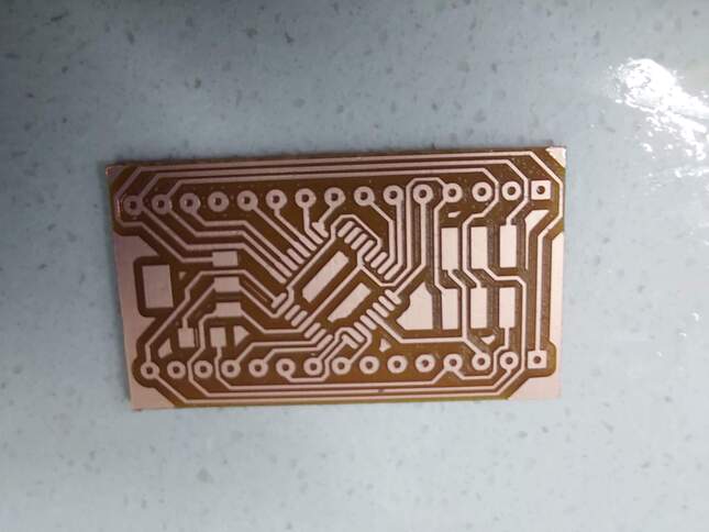
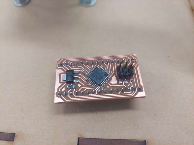
We assemble everything and the result is the following:
Finally, I leave all the designs.
- Download the files here
This is all for this time.