8. Electronics Design
This time, let’s learn about Electronics Design.
Electronic design is the process that allows us to develop integrated circuits for a specific function, using electronic components. use the following.
Also, I used concepts learned in the week of electronic production.
Circuit Test
We’re going to do is use an arduino board, to be able to analyze an operating voltage with an oscilloscope, We’ll use the following components:
- Oscilloscope.
- Arduino UNO.
- Multimeter.
- Led.
- Resistance 330 ohm.
- Protoboard.
- 12V power supply.
- 5V voltage regulator.
Check Operating Voltage
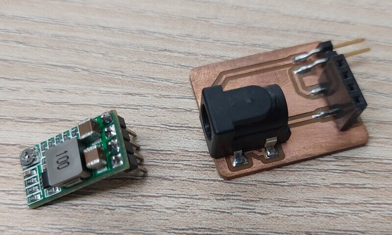
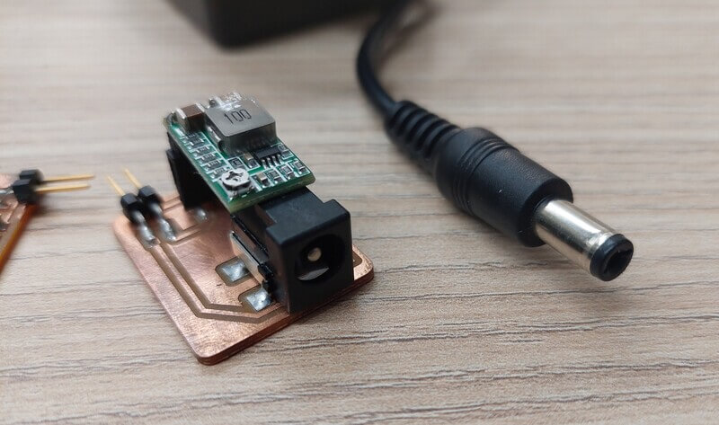
Before carrying out today’s tests, I must explain that I previously designed a PCB that would allow me to connect a 12V power source and regulate to 5V, with a greater current capacity than that provided by a PC USB port, and this PCB is the one I use for these tests, you will find the designs at the end of this section.
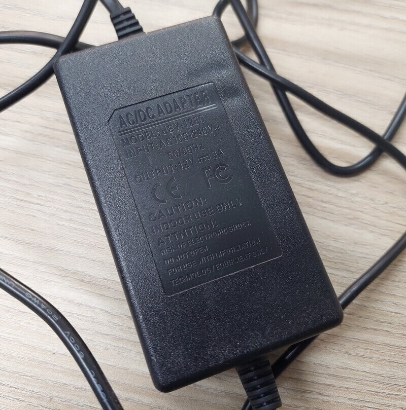
I use a 12V power supply.
the PCB that I design and manufacture uses a voltage regulator that regulates to 5V.
In the following video we can see how a board works with our voltage regulator.
- We can see in the voltmeter that we have a voltage of 5.17 - 5.18 volts.
Check Noise of Operating Voltage
For this part, we continue with the same circuit, but this time we will connect an oscilloscope.
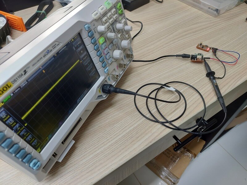
When connecting the oscilloscope, it can be seen that the yellow signal line that was at 0V goes up approximately one square, which would be 5 Volts, but some details of the supply voltage cannot be appreciated very well, so the measurement was scaled and to analyze better this supply voltage, I took a screenshot from the oscilloscope.
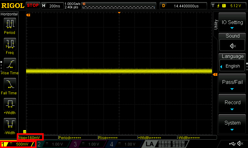
- Here we can appreciate the power that would be the theoretical 5 Volts, but if we observe, it has some small peaks, that would be the voltage operation noise.
- Here we can appreciate the power that would be the theoretical 5 Volts, but if we observe, it has some small peaks, that would be the voltage operation noise.
- In the lower left part we can see two important parts, the first is the scale that is 500mV per frame (vertically) and the other data is Vpp (peak-peak voltage) which is 160mV, to understand it we must think that our voltage It is 5.17V as we saw in the multimeter, but this voltage is not always 5.17V but rather oscillates +- 80mV approx (Vpp/2). this happens at a high frequency, that’s why we don’t see a perfectly straight line, but a line with spikes.
Design
I decided to use EasyEDA due to some not so technical factors, to begin with I was used to using Proteus, but it is not a software that Fab Academy considers in its resources (if you want to review the Fab Academy information I leave the link here), but I did find EasyEDA on the list and I had heard of it before, and it is also used in my university, besides that it is an online editor, and I did not want to struggle with any software to install, the sum of these factors made me decide to explore and use it.
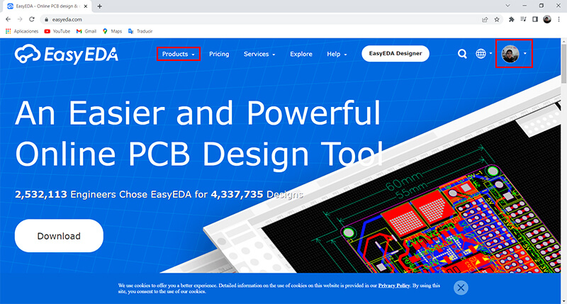
The first thing is to register in EasyEDA, and then in the product tab we can access the online editor. EasyEDA allows us to do electronic design online, with access to many components of its repository.
When we enter the editor, we will find the “Archivos” or “files” tab where we will create a project, also on the right side we have 2 very important options, where we will find the electronic components.
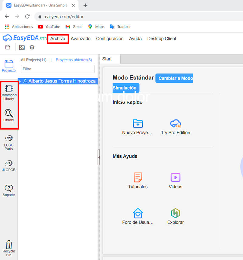
In the “commonly library” section we will find basic components such as resistors, capacitors, etc.
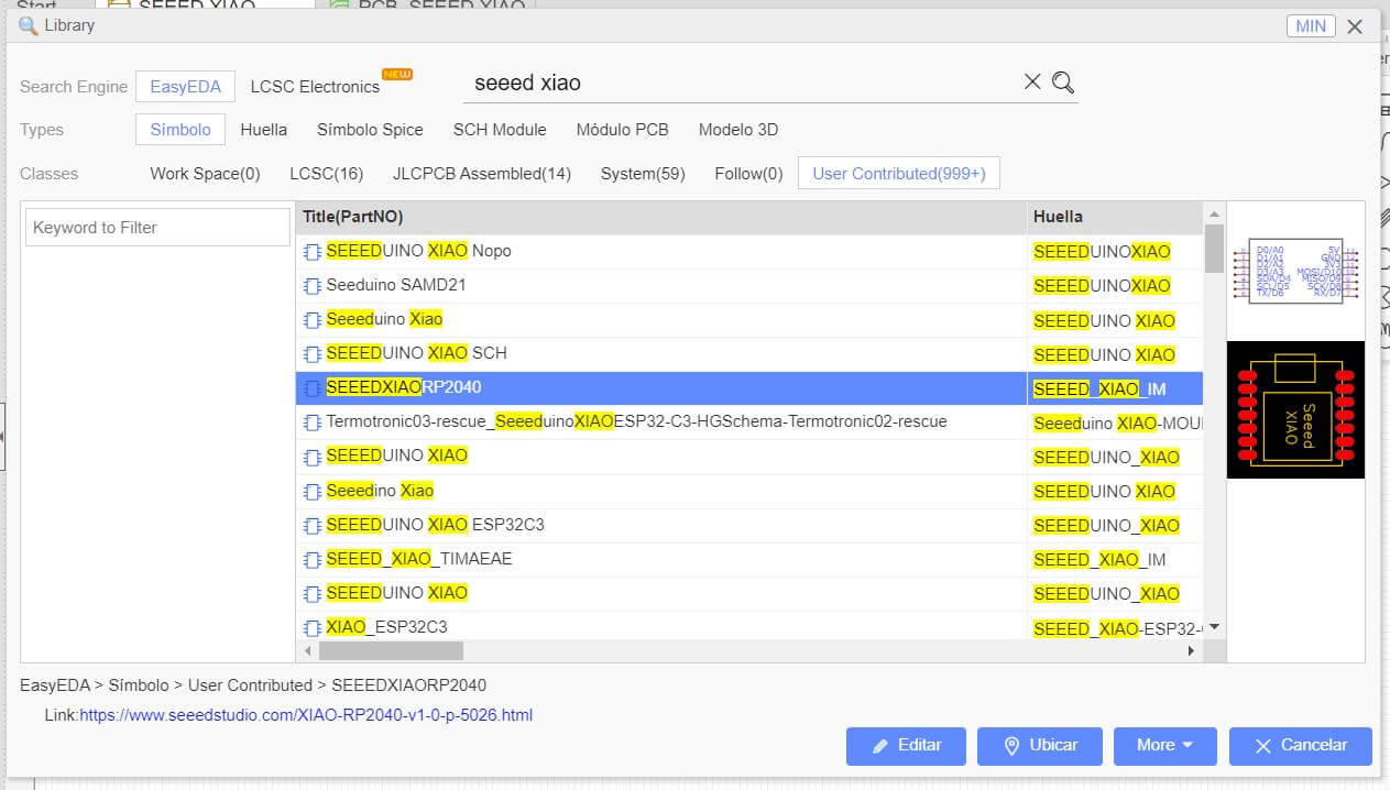
And in the “Library” section we will find a much larger library with more advanced components that were developed by other users and manufacturers, we can use these components, but we must be careful to choose the correct electronic component, because we will find a great variety of the same component , there are components of different formats and/or manufacturers.
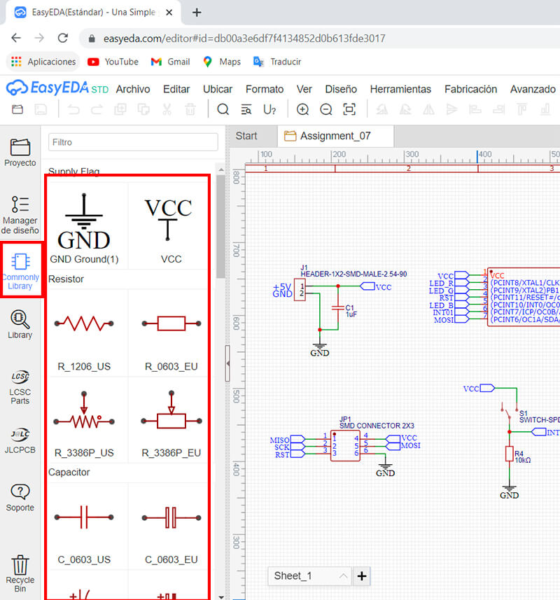
Choosing our electronic components, we can form our circuits, the tools on the top right are useful.
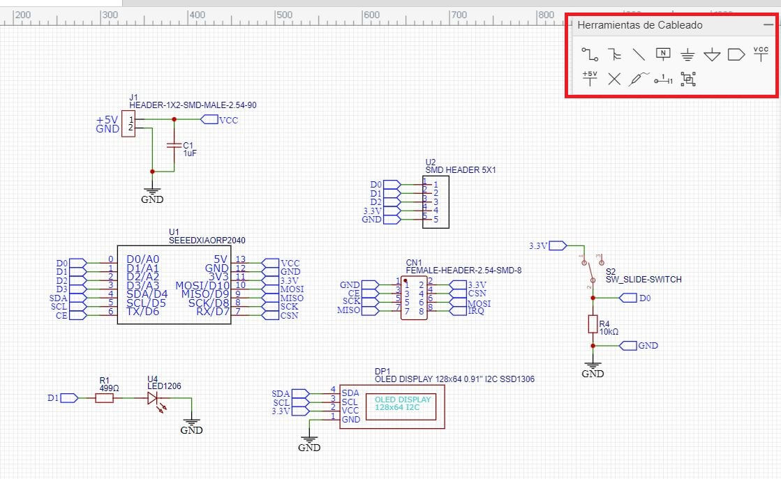
With patience we can form our circuits.
A question you may be asking is: why is there a resistor in series with the switch?
Well, if we pay attention to the switch, and suppose it didn’t have a resistor, what would happen when the switch closes? Well, yes… we would be directly connected VCC to GND, in other words we would make a short circuit.
Remember: the width of the trace in our PCB depends on the current that will pause, for 0.5mA we can use 0.3mm or 0.012” approx. calculate this value with PCB Trace Width Calculator. and as we saw in assignment 4: electronic production, our machine can carry out this work without problems since the minimum we can ask for is 0.006”.
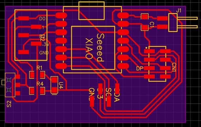
Well!, completed the circuit we have to design the PCB, for that we have the following option.
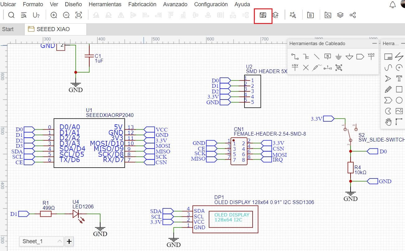
Here we will be shown the components that we use, and we must position and connect them.
Before continuing, I must explain what I designed and what components I used
The microcontroller I chose is the Seeed XIAO, For detailed information you can review my assignment 6 of Embedded Programming Here
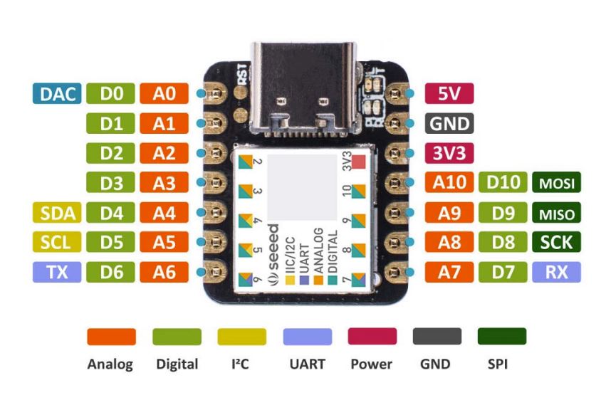
With the identified pins we can work and connect the necessary components.
The necessary components are:
| Components | Quantity |
|---|---|
| Seeed XIAO | 1 |
| Capacitor 1uF | 1 |
| Resistor 499 ohm | 1 |
| Resistor 10k ohm | 1 |
| 2x4 Female header | 1 |
| 1x5 Female header | 1 |
| 1x4 Female header | 1 |
| Switch | 1 |
| 1x2 pin Male angle | 1 |
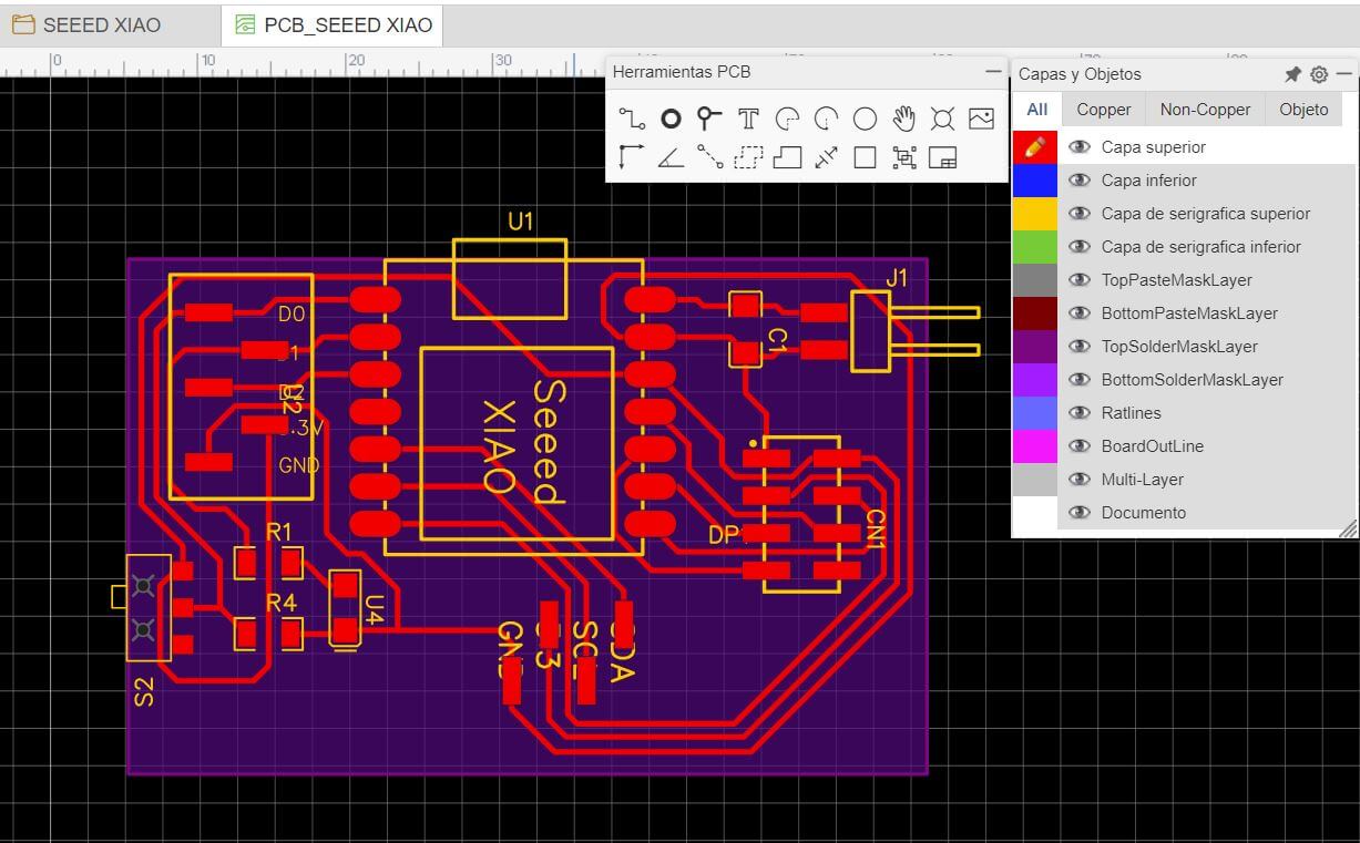
For this design process we rely on a tool, EasyEDA provides a DRC (Design Rule Check) function, which helps us in the routing of our PCB, I must mention that I do not use autorouting, I have bad experiences with other software that have autorouting, Even if you enter the design rules correctly, there is little order in the result, so I better do it manually.
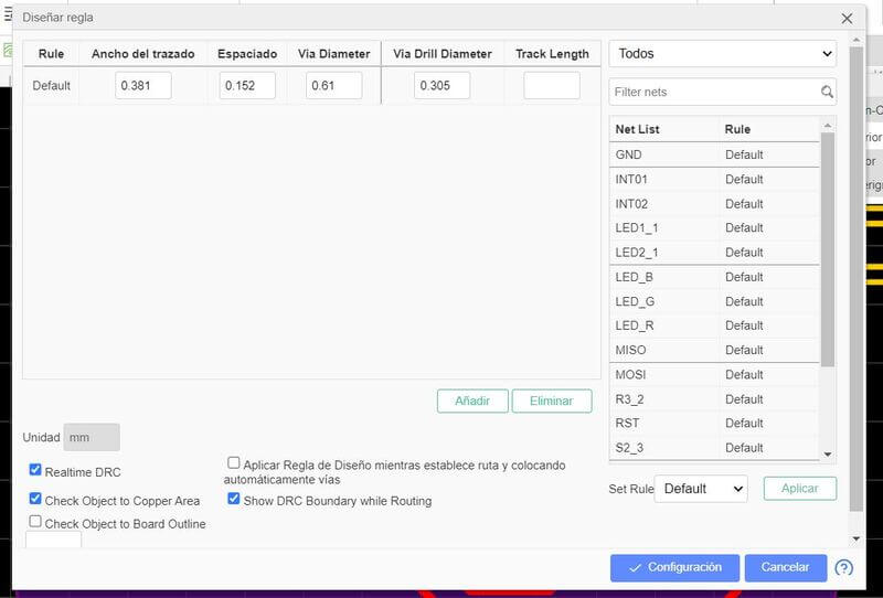
our design rules are:
- Track width: It is the width of the track of the printed circuit board; it cannot be less than this value. In our case we determine a minimum value of 0.3mm, but I used 0.38mm, 0.08 more as a margin of error and more tolerance.
- Clearance : It is the free space of different objects that have a different network. In this case we leave it by default since 0.152mm is within what our machine can work with.
and finally we have…
- Via diameter : The track diameter of the current rule. The via diameter of the PCB cannot be less than this value. As the diameter of the hole / multi-layer pad.
- Via Drill Diameter: The track drill diameter of the current rule. The PCB drilling diameter cannot be less than this value.
These also leave these two values by default but we don’t take much importance to them since our design is a single layer and in SMD format.
To know more details about the use of this tool I leave you the EasyEDA link about this tool, check it here
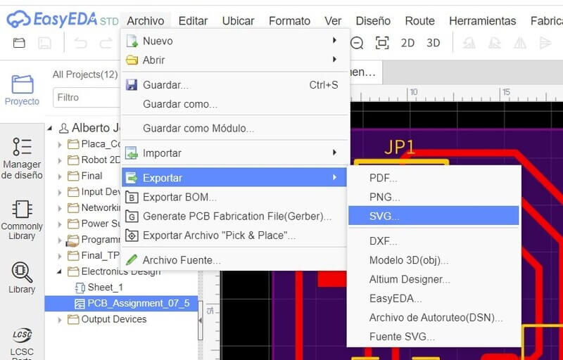
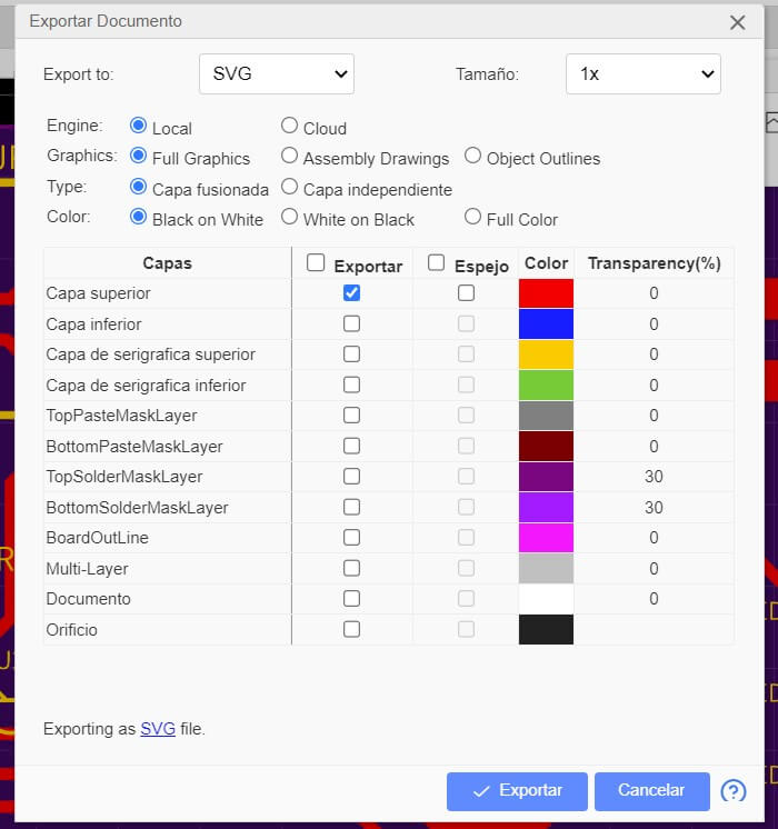
Well!, now one more step with EasyEDA, export our design.
We go to file and then to export as I show in the image.
We select the layers that we want to export, in my case the upper layer, when clicking on export, a file will be downloaded (in my case SVG)
We take that file to Mods CE and then we generate the file for CNC milling, this process and the work with ModsCE I explain in my assignment 4: Electronics Production.
Electronic Circuit
The result is:
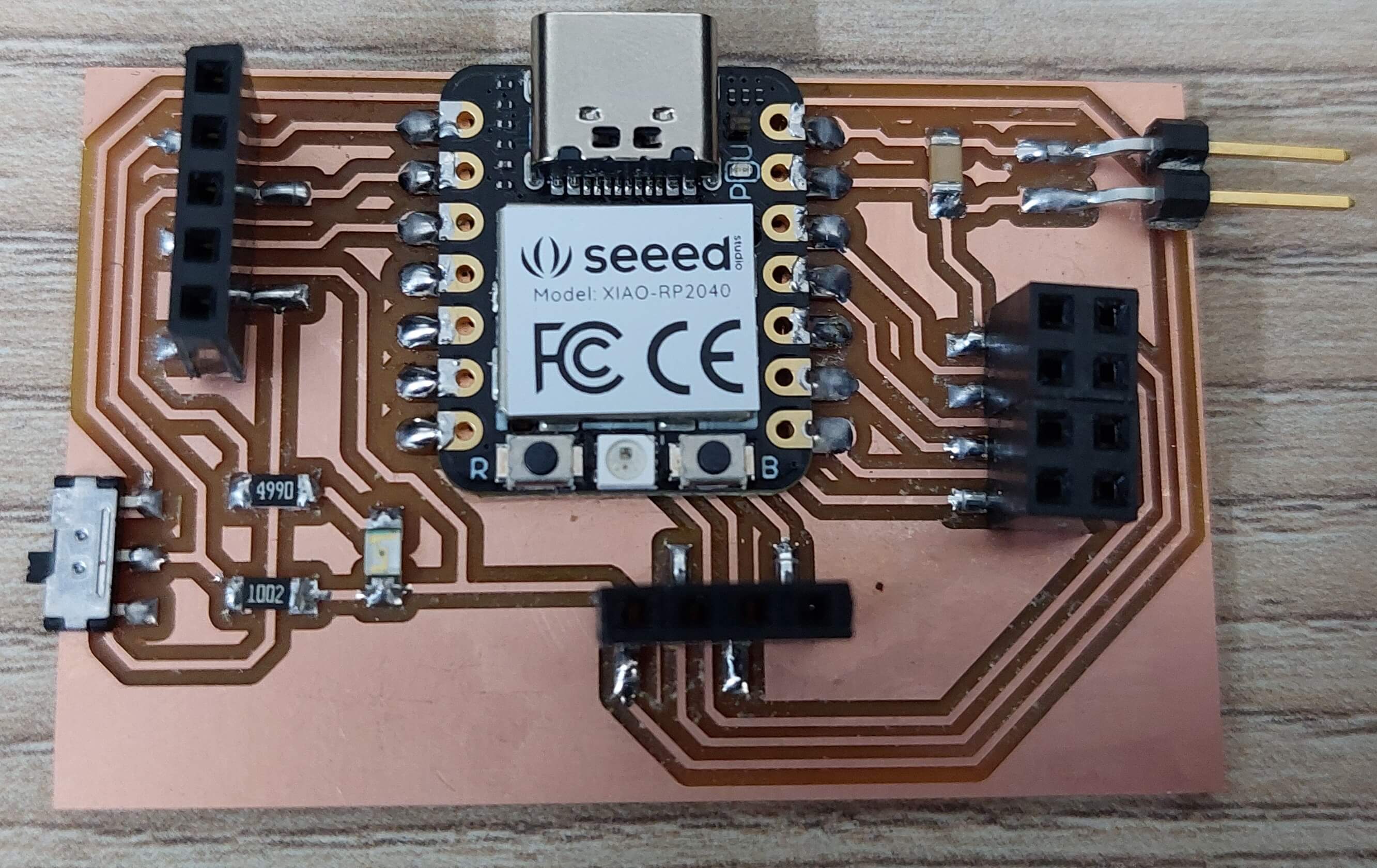
I programmed a traffic light that stops when we activate a switch.
The code is:
int Interrupt = 0;

void setup() {
  pinMode(D0, INPUT);
  pinMode(D1, OUTPUT);
}

void loop() {
  Interrupt = digitalRead(D0);

  if (Interrupt == HIGH){
    digitalWrite(D1, HIGH);
    delay(500);
    digitalWrite(D1, LOW);
    delay(500);
  }
  else{
    digitalWrite(D1, LOW);
  }
}
That’s all for now, we’ll see the electronic production process later…
Finally, I leave all the designs.
- Download the files here
This is all for this time.