6. Embedded Programming
Hello! this time, let’s learn about Embedded Programming.
Today I’ll try to explain the information that I was able to collect on two computer architectures, Von Neumann and Harvard Architecture.
Von Neuman and Harvard Architecture
The main difference between the two is access to data memory and program memory.
- Von Neuman architecture has a single bus that is used to obtain instructions and transfer data.
- Harvard architecture has a separate memory space for instructions and data, physically separates signals and code from storage and memory.
Harvard Architecture
- The CPU is connected to data memory and program memory separately.
- The execution speed is faster because the processor fetches data and instructions simultaneously.
- It results in a waste of space, since if there is space left in data memory, instruction memory cannot use the space in data memory and vice versa.
Von Neuman Architecture
- There is no separate data and program memory. Instead, a single memory connection is provided to the CPU.
- The execution speed is slower since it cannot fetch the data and the instructions at the same time.
- El espacio no se desperdicia porque el espacio de la memoria de datos puede ser utilizado por la memoria de instrucciones y viceversa.
I was able to obtain this information by reading some articles on the internet, I leave you the sources below, but what I present here is what I was able to summarize, and rescue by synthesizing its advantages, disadvantages and where we can find these architectures, both the Harvard and Von Neumann architecture .
- El computador (en español) - by: Miquel Albert Orenga and Gerard Enrique Manonellas.
-
Diferencia entre Von Neumann y la arquitectura de Harvard(en español) - by: unigal.mx
-
Wikipedia (Harvard architecture and Von Neumann architecture)
Now, the question is: what architecture do the microcontrollers we use have?.
- The Harvard architecture is a new concept used specifically in microcontrollers and digital signal processing.
- The von Neumann architecture is generally used in literally all machines, from desktops, laptops, high-performance computers to workstations.
- The Von Neumann architecture is the common architecture of all PC processors. Any and all CPUs, from ARM to x86.
To answer this question… i must introduce you to the controller we will be using.
Seeeduino XIAO
Seeeduino XIAO is the smallest Arduino compatible board in Seeeduino Family. It is an Arduino microcontroller that is embedded with the SAMD21 microchip.
We will use the Seeeduino XIAO for our projects, reviewing its datasheet, we know that it is based on the SAMD21 Cortex M0+ and reviewing the datasheet of this processor we know that it is an ARM so we can deduce that it has the Von Neuman architecture.
Hardware Pinout
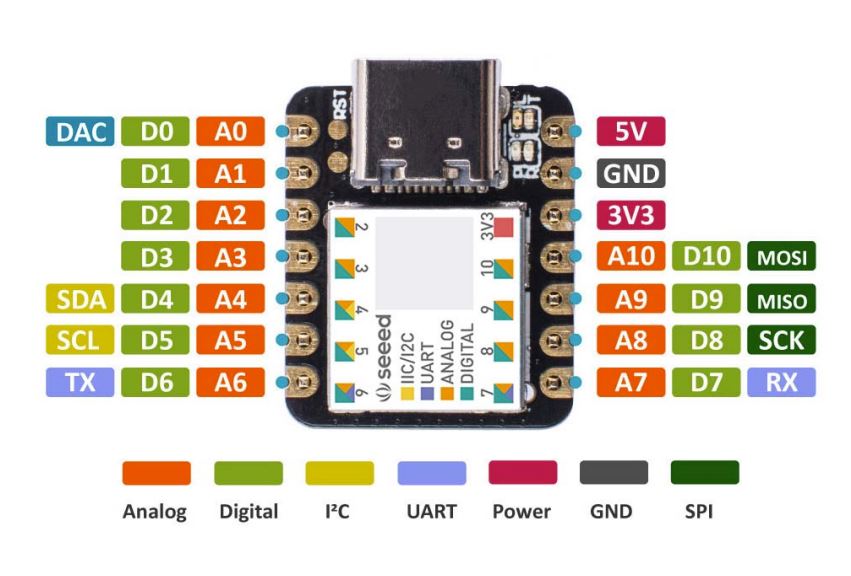
From the image we can summarize that: - We have 10 pins that can be used as digital pins or analog pins. - We have pins for SPI, FTDI and I2C communication.
Now I make the following connections on a breadboard.
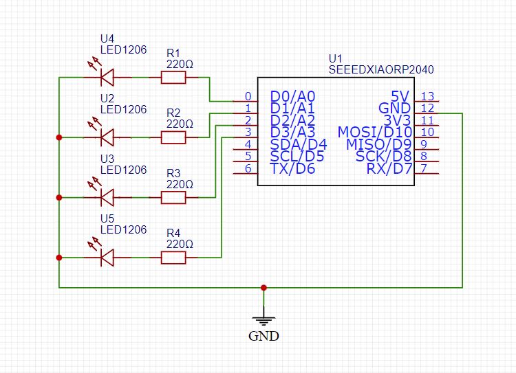
I will use pins D0, D1, D2, D3 as: digital outputs.
But before uploading the code we must get our microcontroller to communicate with our PC, for them we must follow the following steps:
- Enter the Seeed Studio page.
- Install the seeeduino libraries (Raspberry Pi Pico/RP2040).
The information presented on the “Seeed Studio page” is very complete and detailed, but I will also give a summary of the steps to follow to install the library. (Always a good idea to preserve clear information by attributing authorship and source).
When we have the library installed we can program our Seeed XIAO.
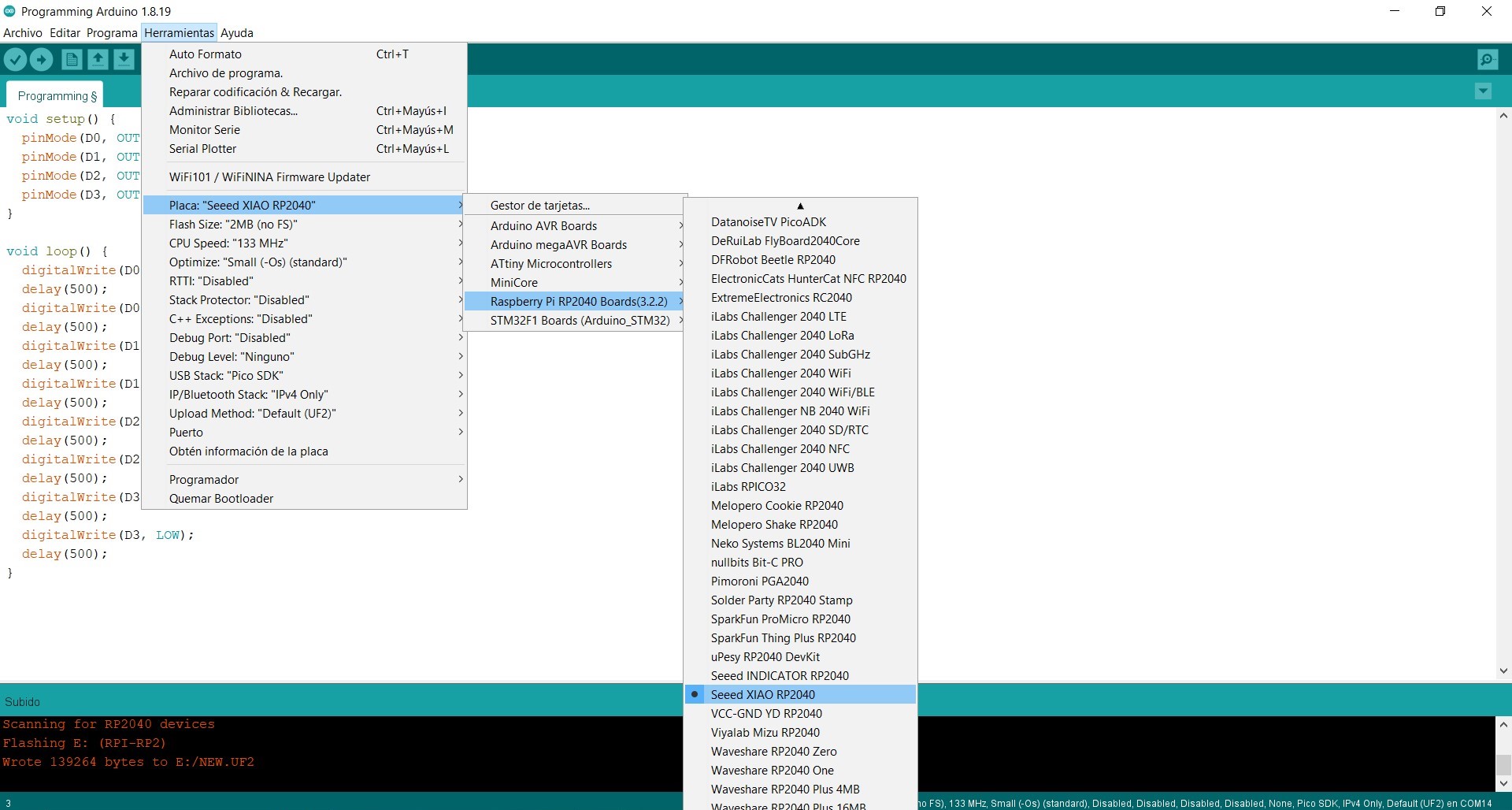
I made a code to test our Seeed XIAO:
void setup() {
  pinMode(D0, OUTPUT);
  pinMode(D1, OUTPUT);
  pinMode(D2, OUTPUT);
  pinMode(D3, OUTPUT);
}

void loop() {
  digitalWrite(D0, HIGH);
  delay(500);
  digitalWrite(D0, LOW);
  delay(500);
  digitalWrite(D1, HIGH);
  delay(500);
  digitalWrite(D1, LOW);
  delay(500);
  digitalWrite(D2, HIGH);
  delay(500);
  digitalWrite(D2, LOW);
  delay(500);
  digitalWrite(D3, HIGH);
  delay(500);
  digitalWrite(D3, LOW);
  delay(500);
}
The code is simple, first we turn on an LED, then turn it off for another half second, then we turn on the next LED for half a second and turn it off for another half second, and so on with 4 LEDs.
Next, I leave the video where we load the code to our Seeeduino.
On this occasion I do not leave the designs because the whole process is more informative and I only used a breadboard for the connections, but I leave you some references so that you can continue investigating this small microcontroller, the Seeed Xiao!!!
- Getting Started with Seeed Studio XIAO SAMD21 Here