10. Input Devices
Hello! this time, let’s learn about Input Devices.
We know as input devices the devices that allow information to be entered into the system.
Equipment and materials
Interpret a signal
I use a fairly simple code. With pin 9 we generate an analog output or PWM (Pulse Width Modulation). I connected a LED to see the effect of the signal. I also connected the oscilloscope to pin 9 and also a digital multimeter to see what happened. The result is this:
We can see the behavior of the signal with the oscilloscope, see the voltage with the multimeter, and see the effects of the signal with a led.
-
To begin with, we must note that a PWM signal is a signal that “turns on and off” in a continuous cycle, depending on the time it remains “activated” more or less voltage will be obtained, and with this we can control for example: the amount of light eu emits the led.
-
In the arduino we can give this signal value, how?, arduino has an 8-bit analog output, that means that we have a control range from 0 to 255, 0 would be 0 volts and 255 would be 5 volts.
-
The code you use increases from 0 to 255, that’s why we see that the “on” time of the signal increases, the code is as follows, you can try it.
The code is the following:
void setup() {
  pinMode(9,OUTPUT);

}

void loop() {
  for (int u = 0; u < 255; u++){
    analogWrite(9,u);
    delay(50);
  }
}
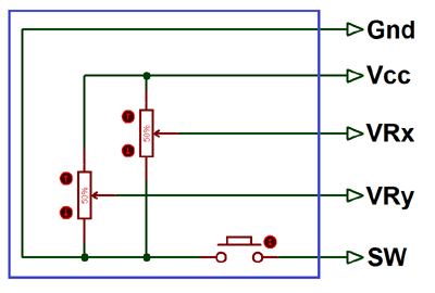
Joystick Module
The Joystick Module, it consists of two Potentiometer, each for one axis (X and Y).
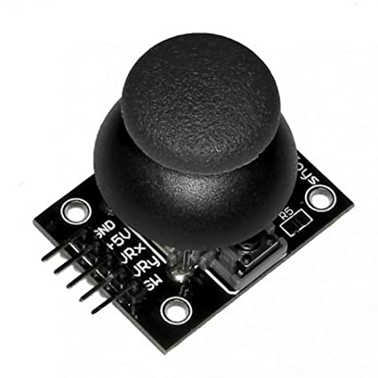
Both 10k potentiometer are independent to move in their particular direction.
Reading Joystick Module
First we connect the joystick to arduino, we will use the analog inputs A0 and A1 for readings, and pin 2 as digital input.
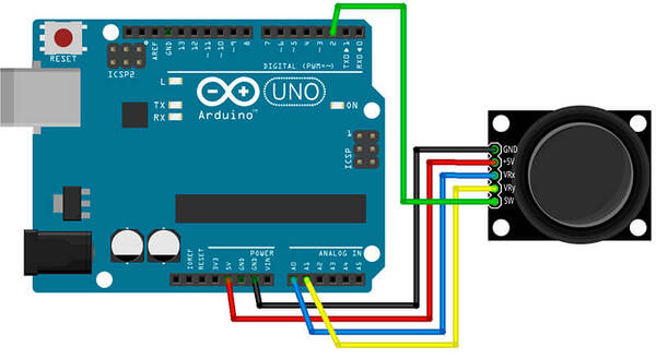
and load the code.
int x_Pin = A0;
int y_Pin = A1;
int button_Pin = 2;

int x_Position = 0;
int y_Position = 0;
int button_State = 0;

void setup(){
  Serial.begin(9600);
  pinMode(button_Pin, INPUT_PULLUP); // we use the internal resistance of Arduino
}

void loop(){
  x_Position = analogRead(x_Pin);
  y_Position = analogRead(y_Pin);
  button_State = digitalRead(button_Pin);

  Serial.print("X: ");
  Serial.print(x_Position);
  Serial.print('\t');
  Serial.print("Y: ");
  Serial.print(y_Position);
  Serial.print('\t');
  Serial.print("Button: ");
  Serial.println(button_State);

  delay(100);
}
We can see readings from 0 to 1023, because the analog input of the arduino is 10 bits, so it registers 1024 values. A signal of 0 Volts corresponds to 0 and 5 Volts corresponds to 1024.
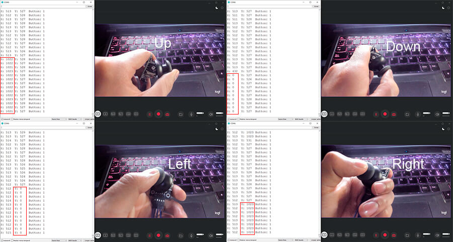
| axi x | axi y | |
|---|---|---|
| Up | 1023 | 527 |
| Down | 0 | 527 |
| Right | 512 | 1023 |
| Left | 512 | 0 |
| Center | 512 | 527 |
It’s important to identify these values for each position or movement.
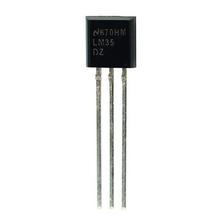
Temperature Sensor LM35
The LM35 is an analog temperature sensor. It’s a very popular sensor for its ease of use and various applications. It doesn’t need any additional circuit to be used. It’s powered directly from a 5V supply and provides an analog output between 0V to 1.5V.
Sensor LM35 Reading
We connect the sensor to the arduino.
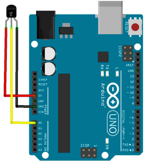
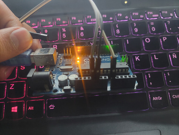
and load the code.
float temp = 0.0;
int temp_Pin = 0;
void setup(){
    Serial.begin(9600);
}
void loop(){
  temp = analogRead(temp_Pin);

  Serial.print("temperature: ");
  Serial.println(temp);
  delay(100);
}
The readings do not correspond to degrees centigrade, these are direct readings in the analog input.
The LM35 sensor has a linear response with a slope of 10mV/ºC. So we can use the following operation to obtain readings in degrees Celsius: temperature(°C) = (5 x reading x 100)/1024.
Modifying the previous code a bit, we include this equation and load the following code.
float temp = 0.0;
float temp_C = 0.0;
int temp_Pin = 0;
void setup(){
    Serial.begin(9600);
}
void loop(){
  temp = analogRead(temp_Pin);
  temp_C = (5.0*temp*100.0)/1024.0;

  Serial.print("temperature: ");
  Serial.print(temp_C);
  Serial.println(" °C");
  delay(100);
}
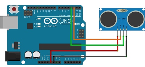
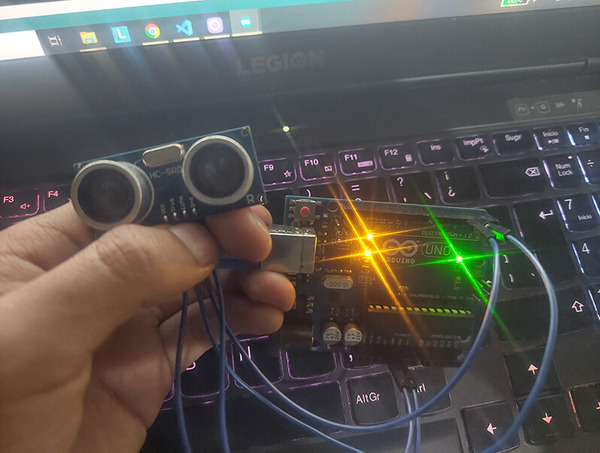
Ultrasonic Sensor HC-SR04
The HC-SR04 sensor is a distance sensor. It has two transducers: a piezoelectric transmitter and receiver.
The operation of the sensor is as follows: the piezoelectric emitter emits 8 ultrasound pulses (40KHz) after receiving the order on the TRIG pin, the sound waves travel in the air and bounce when they find an object, the bounce sound is detected by the piezoelectric receiver, then the ECHO pin changes to High (5V) for a time equal to the time the wave took from when it was emitted until it was detected, the time of the ECO pulse is measured by the microcontroller and thus the distance can be calculated to the object.
Before doing the code, we must know the theory to calculate the distance to an object. We start from the following formula: d = v x t
Where “v” is the speed of sound 340m/s, but we will use the units in cm/us since we will work in centimeters and microseconds, “t” is the time it takes for the ultrasound to reach the object and return to the sensor, and “d ” is twice the distance to the object, substituting in the formula we have: 2d/t = (340m/s) x (1s/100000us) x (100cm/1m), Carrying out the necessary operations, we obtain d(cm) = t(us)/59
and load the code.
const int Trig = 2;
const int Echo = 3;
float tim = 0.0;
float dist = 0.0;

void setup(){
  Serial.begin(9600);
  pinMode(Trig, OUTPUT);
  pinMode(Echo, INPUT);
  digitalWrite(Trig, LOW);
}

void loop(){
  digitalWrite(Trig, HIGH);
  delayMicroseconds(10);
  digitalWrite(Trig, LOW);

  tim = pulseIn(Echo, HIGH);
  dist = tim/59.0;

  Serial.print("Distance: ");
  Serial.print(dist);
  Serial.print("cm");
  Serial.println();

  delay(100);
}
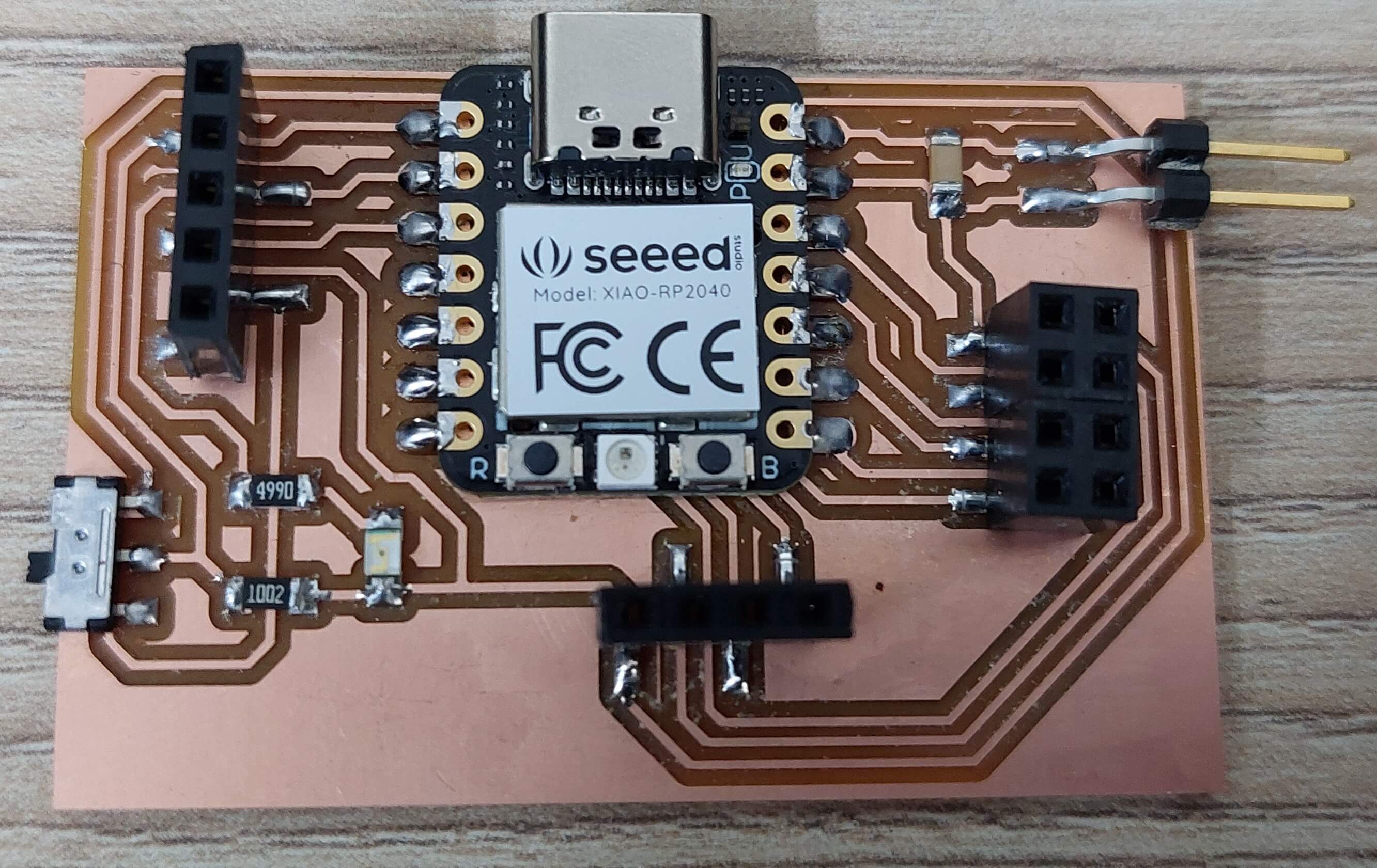
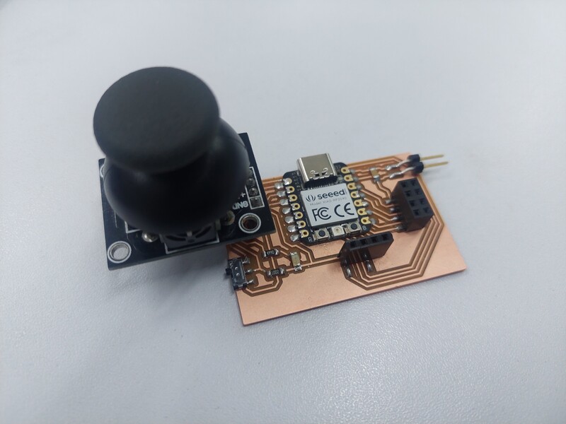
Electronic Design
Now I’ll use our Seeeduino card and connect a joystick:
The code is:
int Xvalue = 0;
int Yvalue = 0;

void setup() {
   Serial.print(9600);
}
void loop() {
  Xvalue = analogRead(A1);
  Yvalue = analogRead(A2);

  if(Xvalue > 612){
    Serial.print("Derecha");
    Serial.print('\t');
  }
  else if(Xvalue < 412){
    Serial.print("Izquierda");
    Serial.print('\t');
  }
  else{
    Serial.print("Centro");
    Serial.print('\t');
  }

  if(Yvalue > 612){
    Serial.print("Arriba");
    Serial.println('\t');
  }
  else if(Yvalue < 412){
    Serial.print("Abajo");
    Serial.println('\t');
  }
  else{
    Serial.print("Centro");
    Serial.println('\t');
  }
}
Finally, I leave all the designs.
- Download the files here
This is all for this time.