13. Networking and communications
Hello! this time, let’s learn about Networking and communications.
An important part is the communication between devices and/or projects, so today I will take the opportunity to talk about two communication methods, SPI and I2C.
SPI (Serial Peripheral Interface)
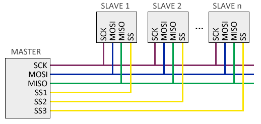
The SPI (Serial Peripheral Interface) bus was developed by Motorola in 1980. It has a master-slave architecture. The master device (master) can initiate communication with one or more slave devices (slave), and send or receive data from them. On the SPI bus, data communication between masters and slaves is carried out on two independent lines, one from the master to the slaves, and another from the slaves to the master. Therefore, the communication is Full Duplex, that is, the master can send and receive data simultaneously.
The SPI bus requires a minimum of 3 lines
- MOSI (Master-out, slave-in) for communication from master to slave.
- MISO (Master-in, slave-out) for communication from the slave to the master.
- SCK (Clock) clock signal sent by the master.
SPI characteristics
- High transmission speed and Full Duplex.
- It can send bit streams of any size, without splitting and without interruptions.
- 3 cables (SCK, MOSI and MISO) + 1 additional cable (SS) are required for each slave device.
- There is no control mechanism available, that is, we cannot know if the message has been received and even less if it has been - received correctly.
I2C (Inter-Integrated Circuit)
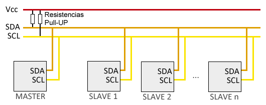
The I2C (Inter-Integrated Circuit) standard was developed by Philips in 1982 for the internal communication of electronic devices in its articles. The I2C bus requires only two cables for its operation, one for the clock signal (CLK) and another for the data transmission (SDA), which is an advantage over the SPI bus. The I2C bus has a master-slave architecture. The master device initiates communication with the slaves, and can send or receive data from the slaves. Slaves cannot start communication (master has to ask them).
The SPI bus requires of 2 lines
- SDA (Serial Data)
- SCL (Serial CLock)
I2C characteristics
- Requires few cables.
- It has mechanisms to verify that the signal has arrived.
- His speed is medium-low.
- It isn’t full duplex.
Communication
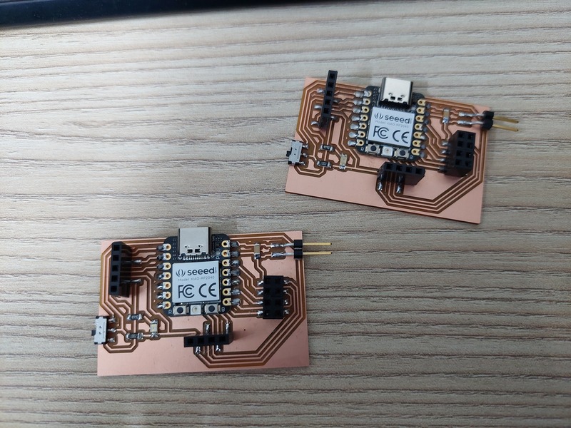
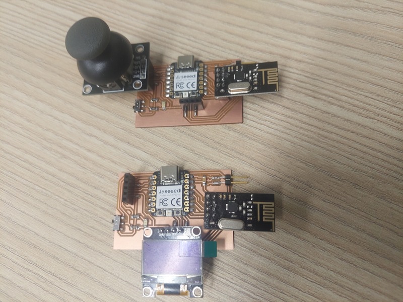
For this assignment, we need another PCB so now we will have two PCBs, if you are interested in knowing how this PCB was made you can check my Assignment 4 and my Assignment 8
Also, we use other components:
- 1 Joystick Module.
- 1 Display OLED.
- 2 Modules NRF24L01.
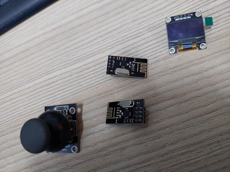
The objective is to send information by RF from the first PCB (with jostick) to the second PCB (with OLED display).
The first thing is the issuer code, in the code we send data from top, bottom, left, right and center.
#include <SPI.h>
#include <nRF24L01.h>
#include <RF24.h>

#define CE_PIN D6
#define CSN_PIN D7

byte direccion[5] ={'c','a','n','a','l'};

RF24 radio(CE_PIN, CSN_PIN);

float datos[2];

void setup(){
  radio.begin();
  Serial.begin(9600);
  radio.openWritingPipe(direccion);
}

void loop(){
  int Xvalue = analogRead(A2);
  int Yvalue = analogRead(A1);

  if(Xvalue > 612){
    datos[0] = 1; //Derecha or Right
  }
  else if(Xvalue < 412){
    datos[0] = 2; //Izquierda or Left
  }
  else{
    datos[0] = 3; //Centro or Center
  }

  if(Yvalue > 612){
    datos[1] = 1; //Arriba or Up
  }
  else if(Yvalue < 412){
    datos[1] = 2; //Abajo or Down
  }
  else{
    datos[1] = 3; //Centro or Center
  }

  bool ok = radio.write(datos, sizeof(datos));
  Serial.print(datos[0]);
  Serial.print('\t');
  Serial.println(datos[1]);

  delay(50);
}
Now the receiver code:
#include <SPI.h>
#include <nRF24L01.h>
#include <RF24.h>

#include <Wire.h>
#include <Adafruit_GFX.h>
#include <Adafruit_SSD1306.h>

#define CE_PIN D6
#define CSN_PIN D7

#define SCREEN_WIDTH 128
#define SCREEN_HEIGHT 64

Adafruit_SSD1306 display(SCREEN_WIDTH, SCREEN_HEIGHT, &Wire, -1);

byte direccion[5] ={'c','a','n','a','l'};

RF24 radio(CE_PIN, CSN_PIN);

float datos[2];

void setup(){
  radio.begin();
  Serial.begin(9600);
  radio.openReadingPipe(1, direccion);
  radio.startListening();

  display.begin(SSD1306_SWITCHCAPVCC, 0x3C);
  delay(500);
  display.clearDisplay();
  display.setTextColor(WHITE);
  display.setTextSize(1);
}

void loop() {
  uint8_t numero_canal;
  if (radio.available()){
    radio.read(datos,sizeof(datos));
    if (datos[0] == 1){
      display.setCursor(0, 30);
      display.println("Left");
    }
    else if (datos[0] == 2){
      display.setCursor(80, 30);
      display.println("Right");
    }
    else if (datos[0] == 3){
      display.setCursor(40, 30);
      display.println("Center");
    }
    if (datos[1] == 1){
      display.setCursor(50, 0);
      display.println("Up");
    }
    else if (datos[1] == 2){
      display.setCursor(40, 50);
      display.println("Down");
    }
    else if (datos[1] == 3){
      display.setCursor(40, 30);
      display.println("Center");
    }
    display.display();
    display.clearDisplay();
  }
  delay(50);
}
Here we receive the data and display it in different positions on the screen, from the right to the right, from the top to the top, and so on.
the first PCB is connected to the PC, and the second PCB is connected to an independent power bank.