7. Computer Controlled Machining
Hello! this time, let’s learn about Computer Controlled Machining.
Computer Numerical Control (CNC)
Computer numerical control (or more commonly known as CNC) is a system that allows the position of a physical element to be controlled at all times. Usually a tool, which is mounted on a machine.
Equipment and materials
- CNC equipment
- MDF 18mm
- Safety equipment
the milling cutters we use are:
- Milling cutters 1/4 in
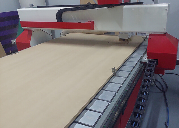
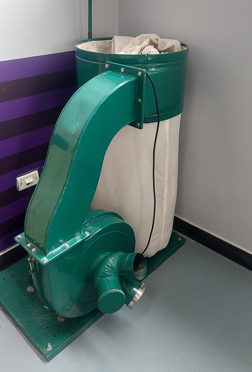
The first step is to identify the safety equipment and accessories, first we identify the workspace of the equipment and, an important element is the chip extractor.
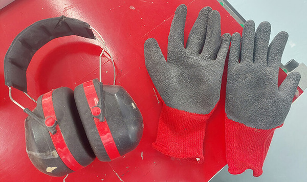
We also use security implements.
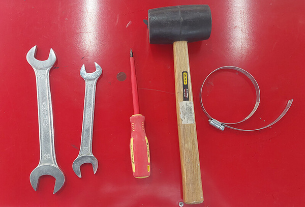
And some additional tools.
It’s important to wear hearing protectors the entire time the equipment is in operation.
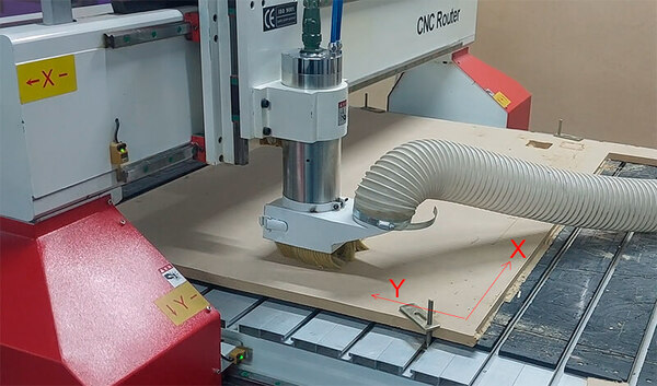
it’s necessary to identify the orientation and work trajectories of the equipment. the origin and work direction is the first thing to identify.
We carry out some tests. Some learnings were:
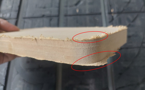
- Burrs on the surface can be caused by rapid advancement of the tool or by Milling cutters dull.
- In the lower part the tool didn’t go through the material, this tells us that we must make the tool descend more.
After some tests, we got:
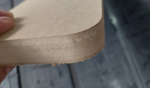
The solutions that we applied were: reduce the speed of advance and that the milling cutter descends 0.5 millimeters more.
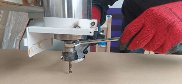
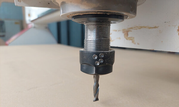
Before continuing, I must mention that before any test we must choose a milling cutter , and fix it well with the respective tools, this is important both for leveling, positioning and knowing the diameter of the milling cutter.
Montessori chair
Design
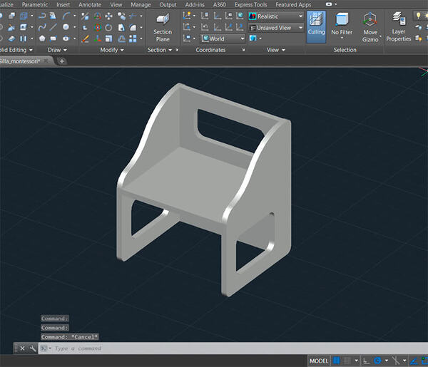
The idea of something to mill is based on a montessori chair. the first step is to design it.
To work in the cnc we must check the corners, and we must apply: Run Past, T Bone or Dog Bone.
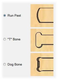
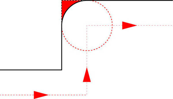
The reason for this is that the cutters are circular in shape due to rotation, which can’t form a corner.
I decide to work with the T bone configuration in the joints.
When we have the design and considerations ready, we can move on to the CAM software. this time I work with RhinoCAM, then we’ll explain the workflow with software for managing the CNC equipment.
Rhinoceros and RhinoCAM
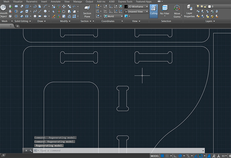
First we must install Rhinoceros and RhinoCAM, in that order. In Rhinoceros, we open the design file in DXF format.
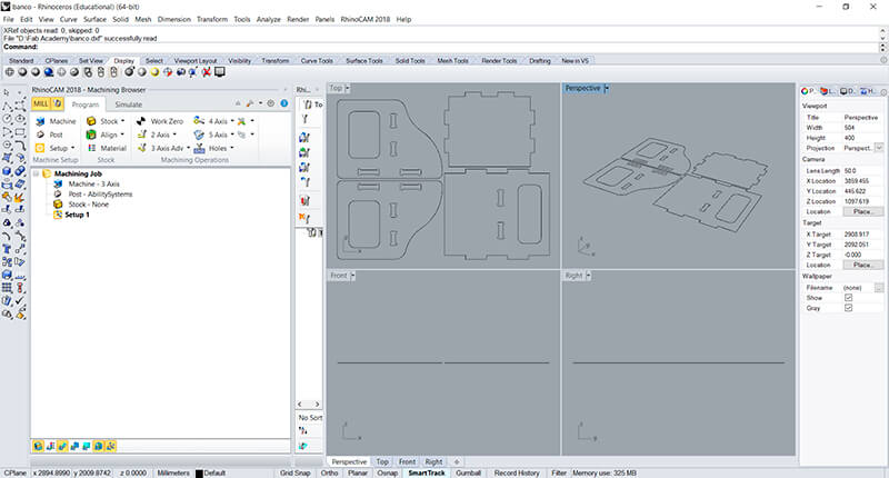
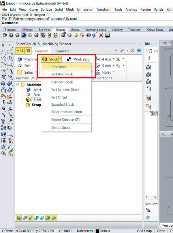
The first thing is to create a box stock.
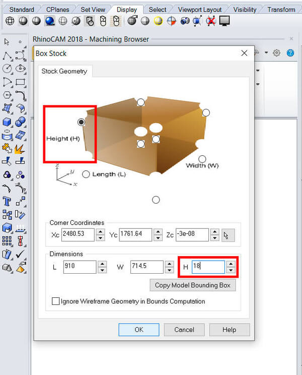
In the box stock the first thing is to define the height. Remember that the material we use is 18mm MDF.
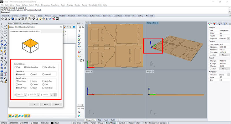
The next thing is to establish the origin of coordinates.
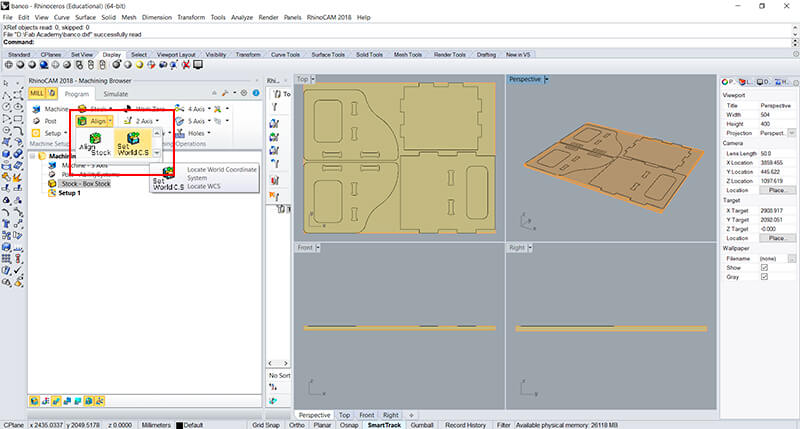
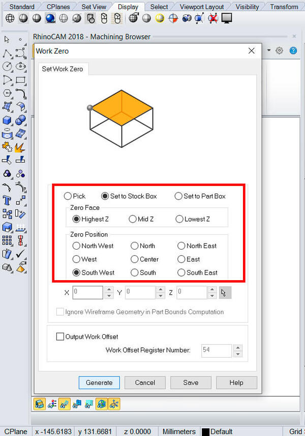
We must also create the work zero.
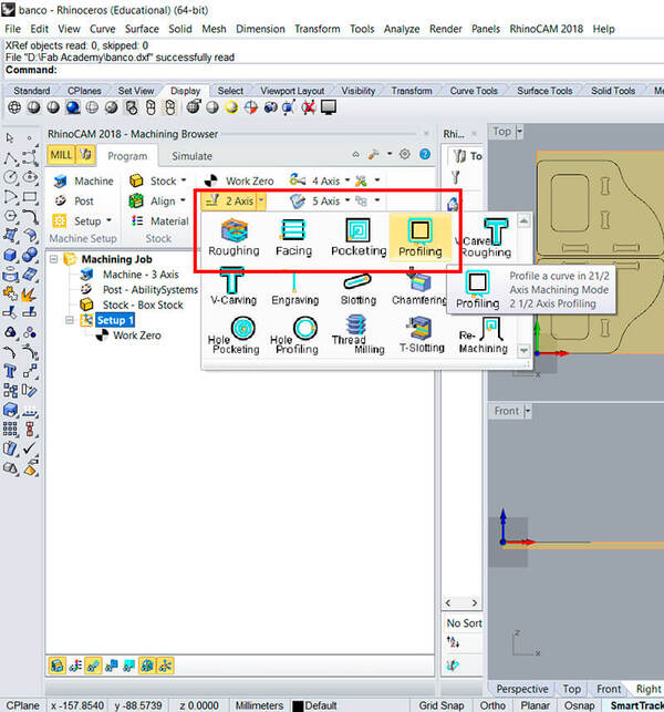
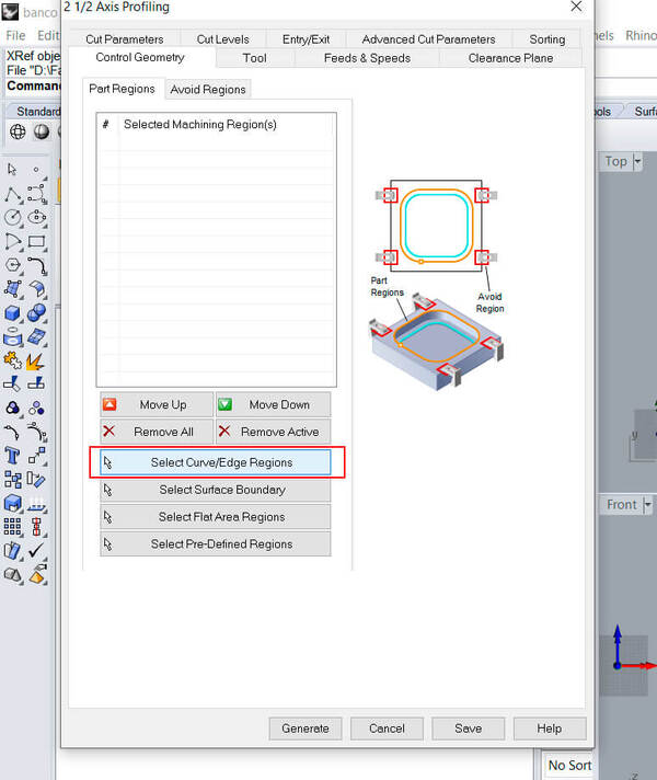
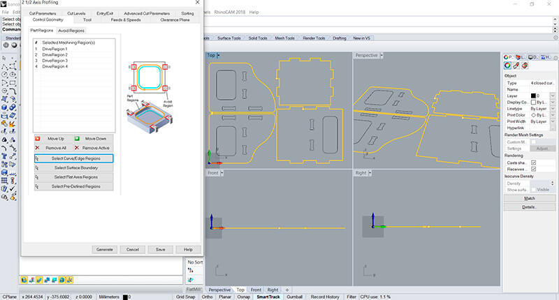
Then we must establish the work parameters, and the first thing is to choose the profiling method.
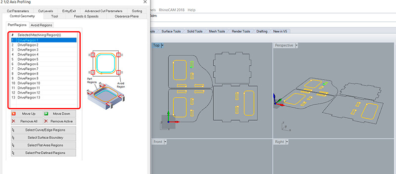
A window will open, and our first action is to select the work paths.
First we must select the interior spaces. This selection is added to the list of the created window.
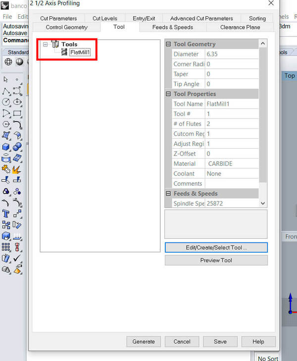
Then we have to configure the tool.
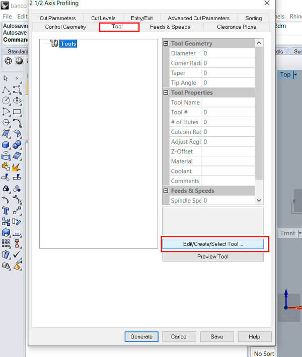
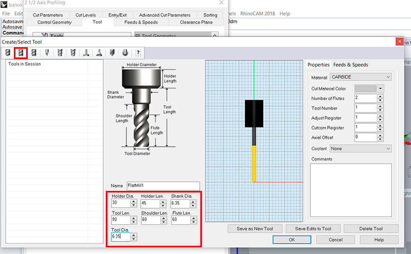
We must ensure that the tool we configure is created.
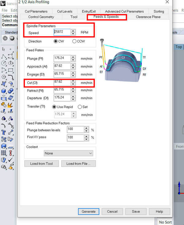
The next thing is to configure feeds and speeds. It’s important to check the speeds of: Spindle and Cut.
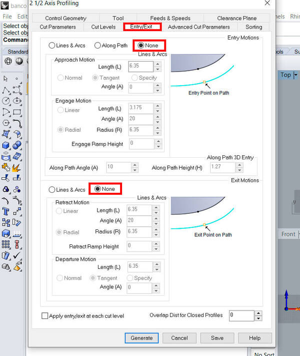
The next configuration is “Entry/Exit” in this case, we select none in both cases, since the spaces of the fingers are reduced.
Finally, we must configure the Cut Levels, the first thing is to determine the cutting depth in 18mm (equal to the material) and the depth for each level, 6mm in this case, this gives us 3 cutting levels.
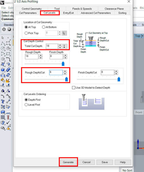
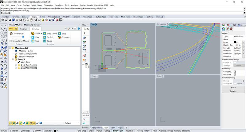
Completed all this, we click on “Generate”.
And we repeat this whole process for the outer cuts.
We can also review the trajectories and the simulation to verify that the work is correct.
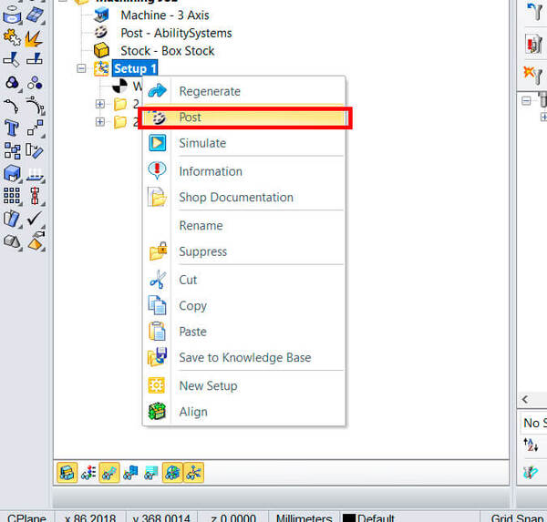
Finally, we right click on “setup 1” and click on the “Post” option, and we will save a “.nc” file that contains a GCode.
We save the file on a USB and go to the CNC equipment. From here, the team will start working and we must respect the safety regulations, use the protective equipment, keep a safe distance, etc.
Making the chair
When the machine finishes cutting, we clean and remove the pieces.
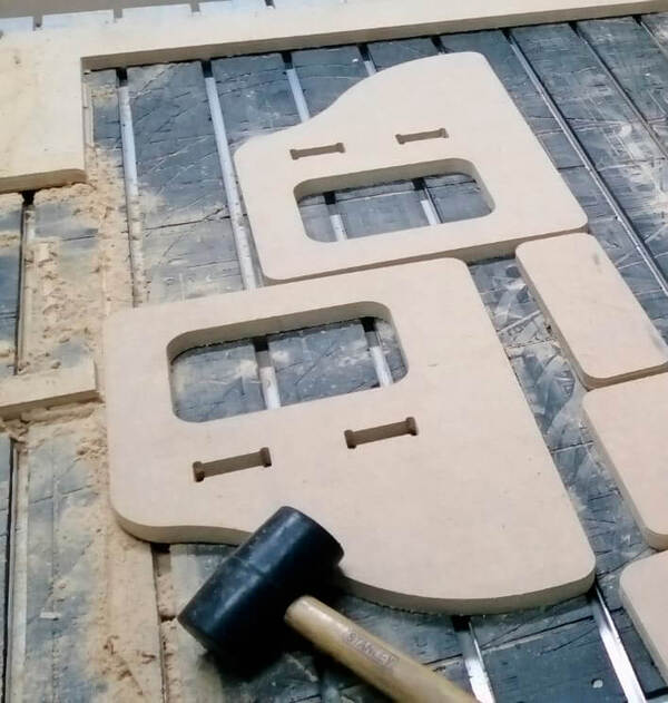
Now it’s time to assemble the chair, we use a rubber mallet to help us,
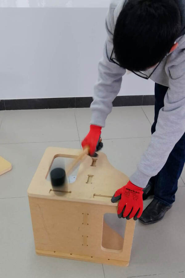
With the chair assembled…
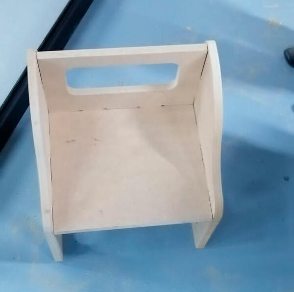
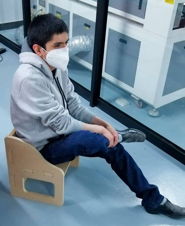
We can test it!
Finally, I leave all the designs.
- Download the files here
This is all for this time.