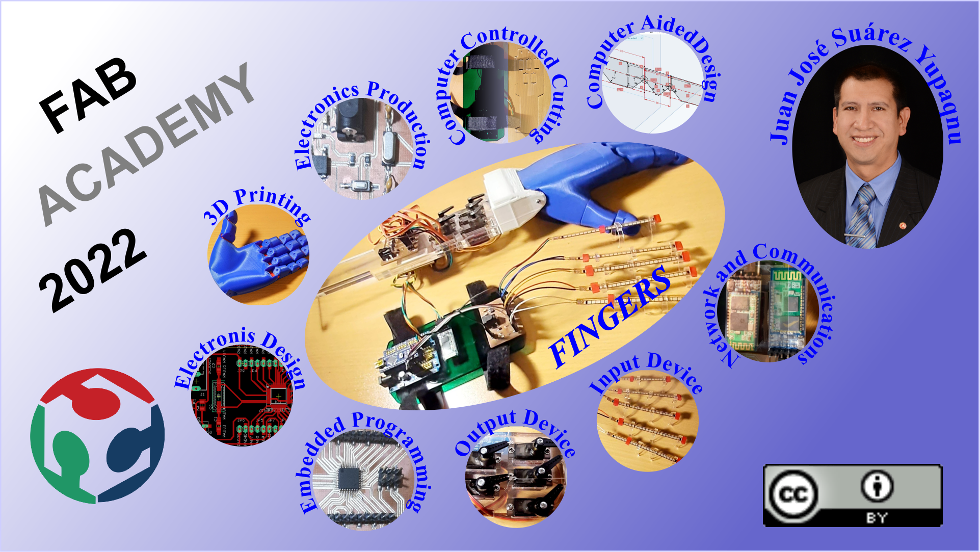
Final Project
My project is called “Fingers”
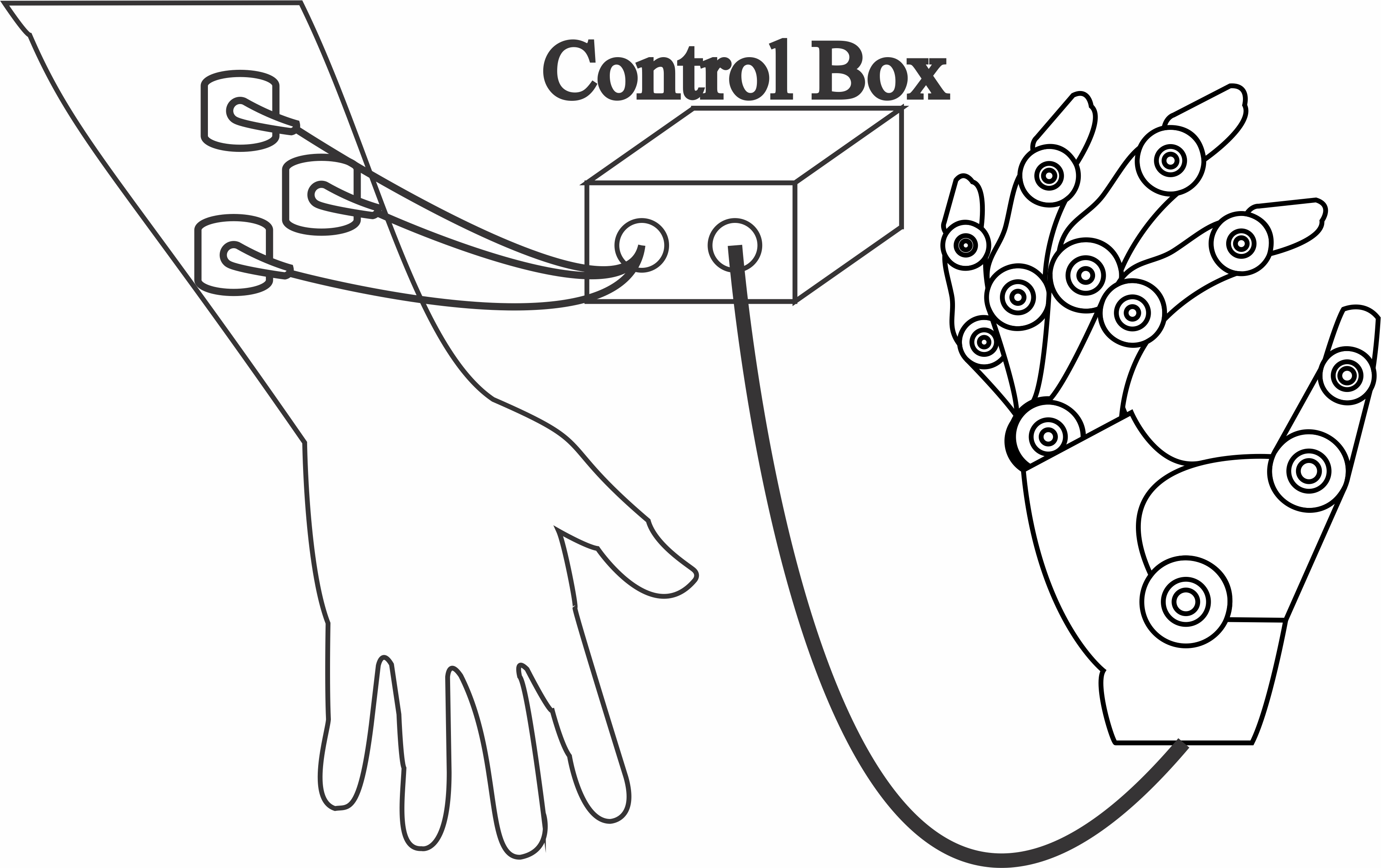
Artificial hand that imitate the movement of the human hand
I developed an artificial hand that mimics the movements of the fingers of the human hand.
My inspiration
As a Higher Technical Education Teacher, I am always looking for ways for students to maintain learning motivation in the subjects I teach, these subjects are usually fundamentals of electronics, so to arouse greater interest in them I was inspired by a person who used static prostheses in both hands, I began to think about how life would change if this person could have a prosthesis with independent movement in each of their fingers, it was then that it occurred to me to develop this project which I call FINGERS
Initially I wanted to control it with myoelectric signals, but as a project for my students it would go beyond the objectives requested by the curriculum, so I adapted the project so that the students achieve the desired objectives.
Project development
I used Computer-aided Design tools to carry out 2D and 3D designs. The program that was used was FUSION 360.
We will surely show some images of the designs made:
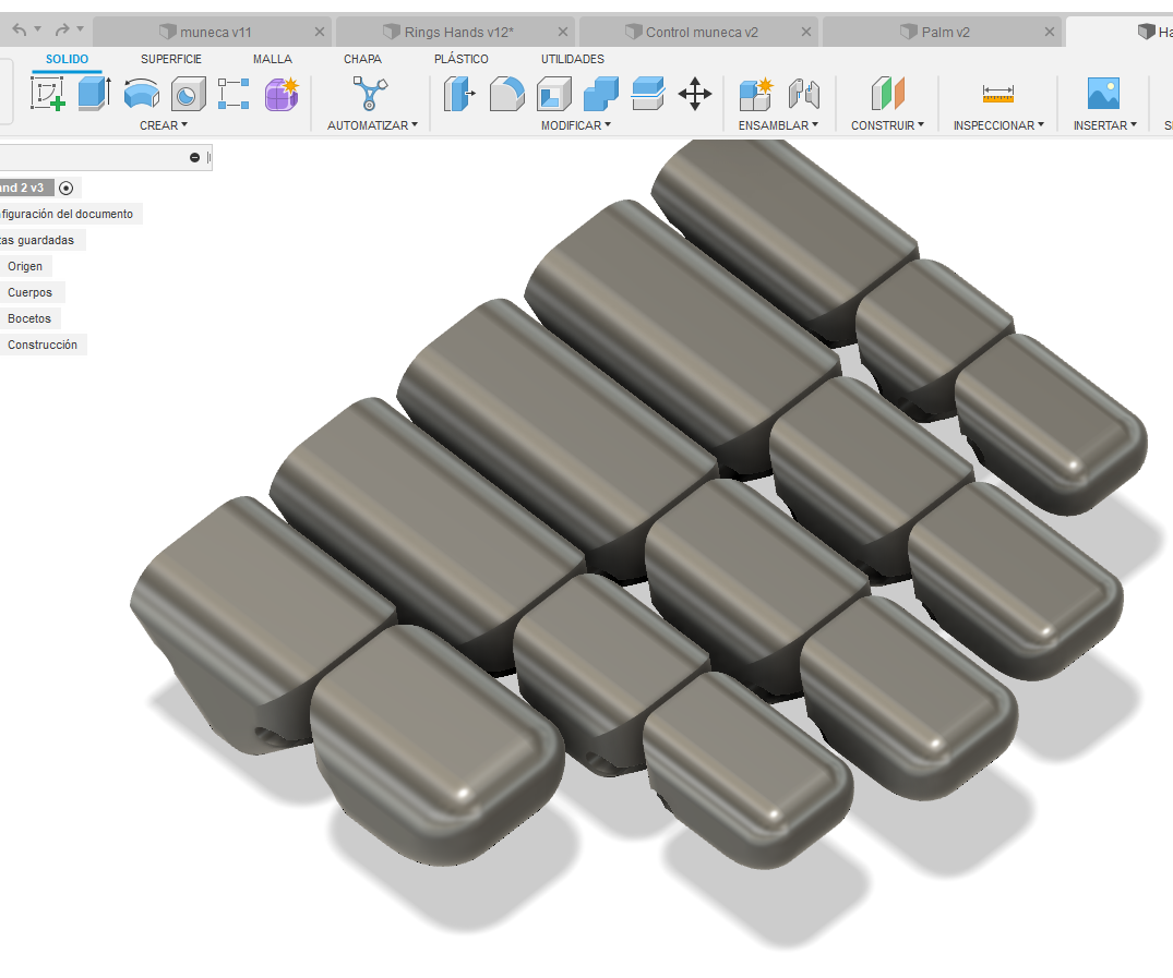
Finger design
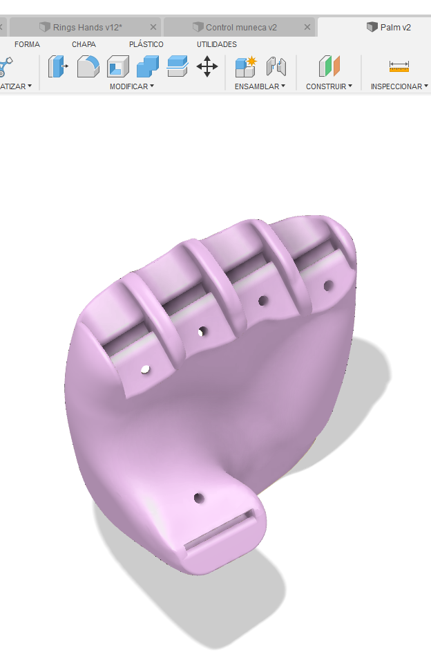
Palm design
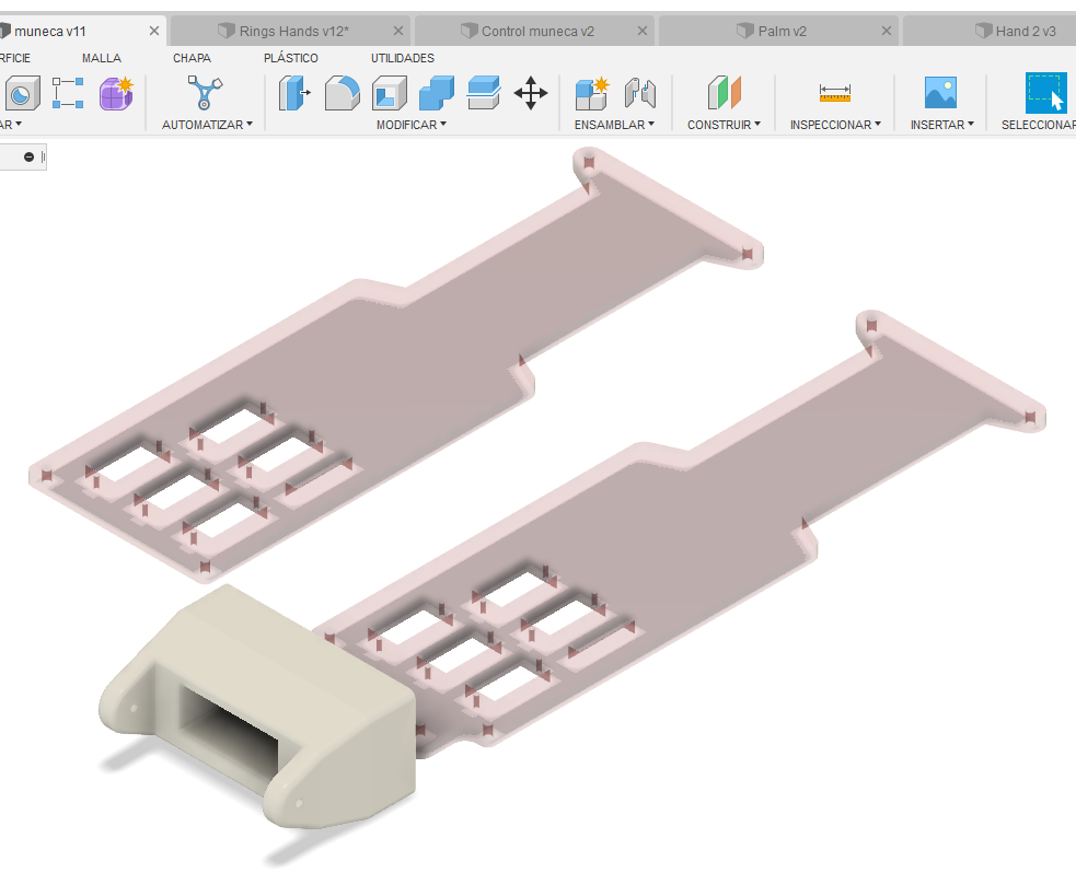
Design of the hand support and circuits
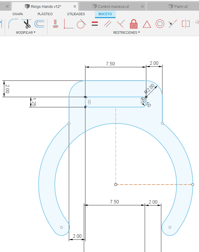
Ring design for control sensors
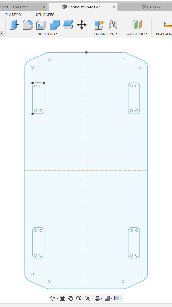
Design of the support for control circuits
I used 3D Printing and Computer Controlled Cutting
Making use of 3D printers and the laser cutter we manufacture the artificial hand and supports both for the hand and for the circuits, we will surely show some of these
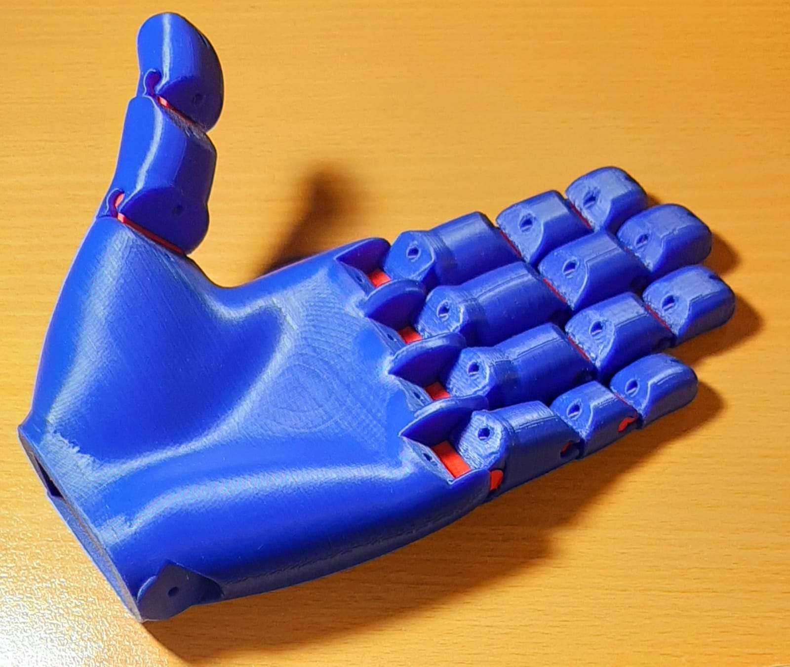
Completely hand made in 3D printer.
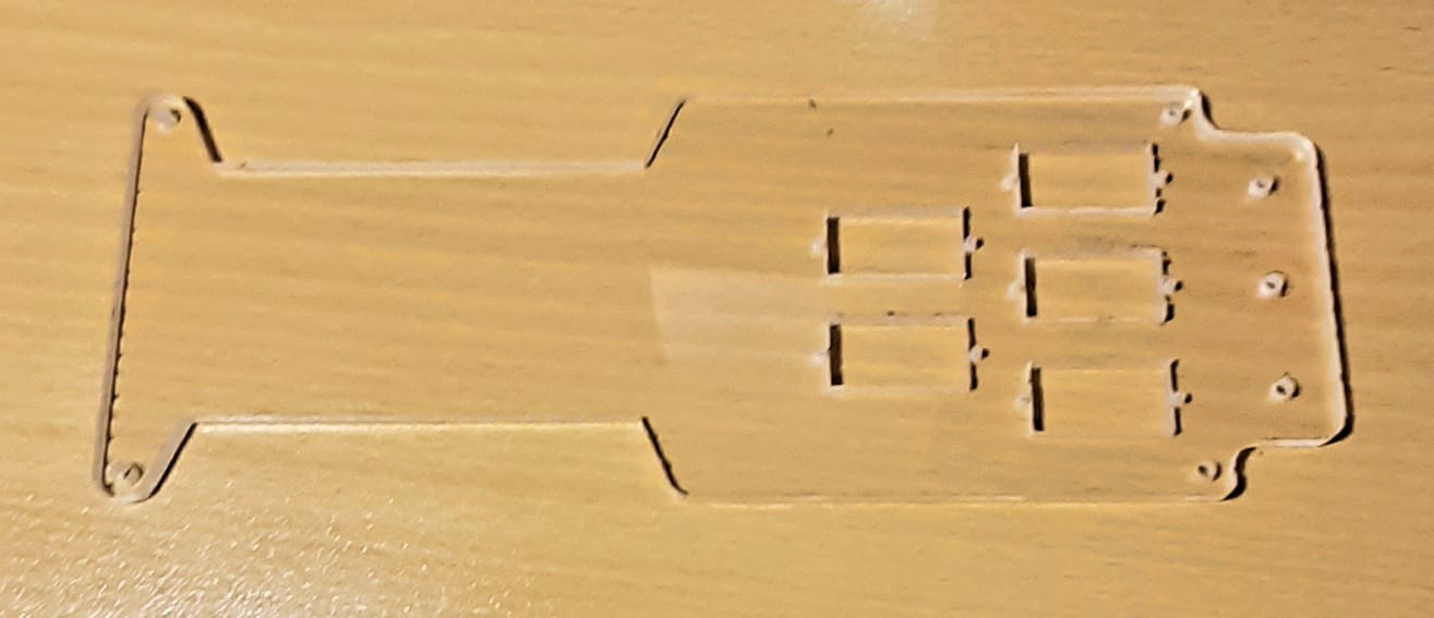
Support for circuits and servos made of acrylic with a laser cutter.
Support for control circuits made of acrylic with a laser cutter.
I used electronic design, electronic production and embedded programming
For the electronic design I used Eagle, the gerber files were generated and the cards were manufactured at the CNC Monofab, I also made control programs for microcontrollers.
Here we show some images:
Electronic Design

Schematic of my generic PCB for the ATmega328p microcontroller.
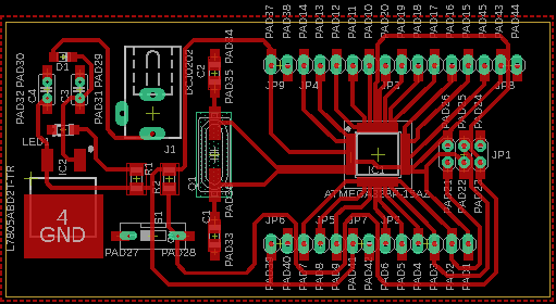
PCB design for the microcontroller.
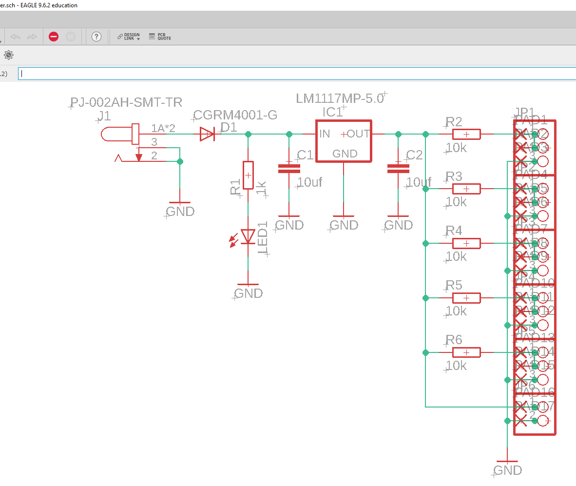
Diagram for the sensor connection circuit.
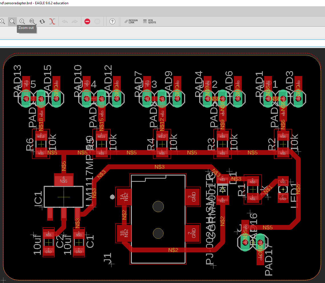
PCB design to connect the sensors.
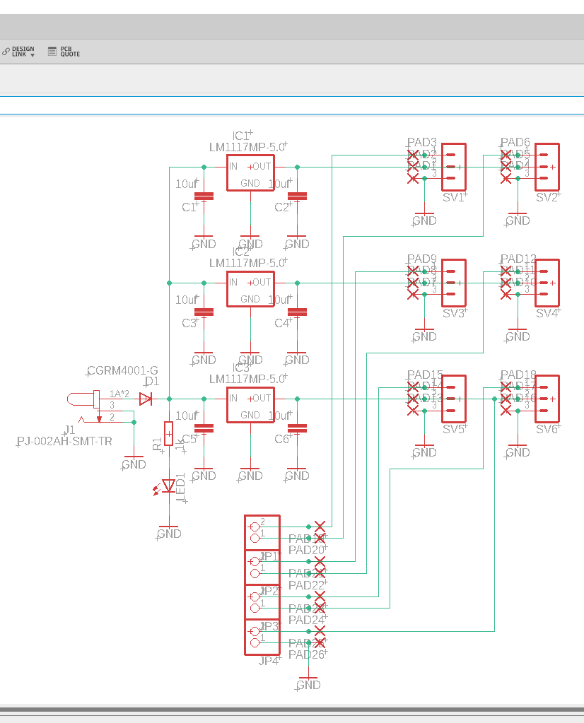
Diagram of the servomotor power supply circuit.
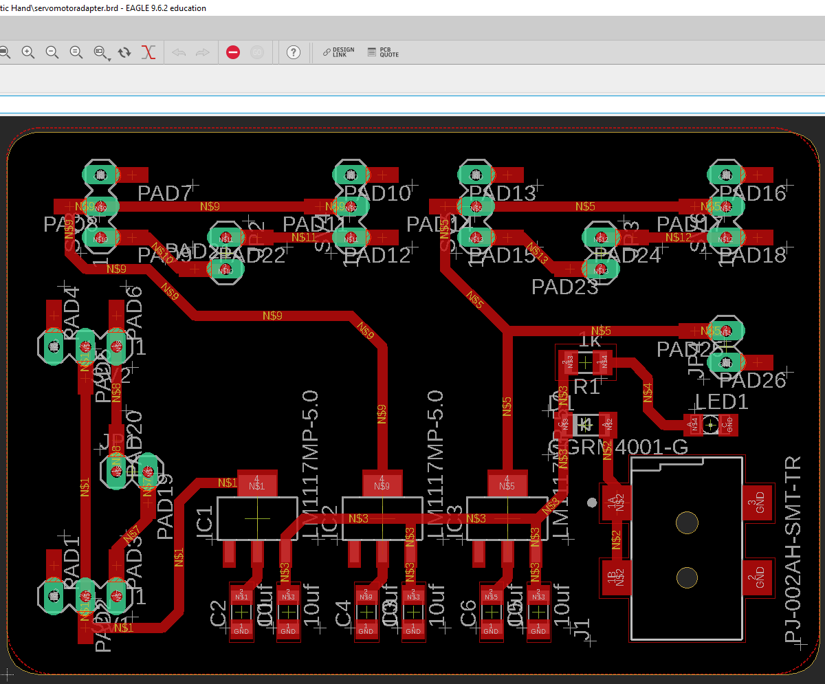
PCB design to connect the servomotors.
Electronic Production
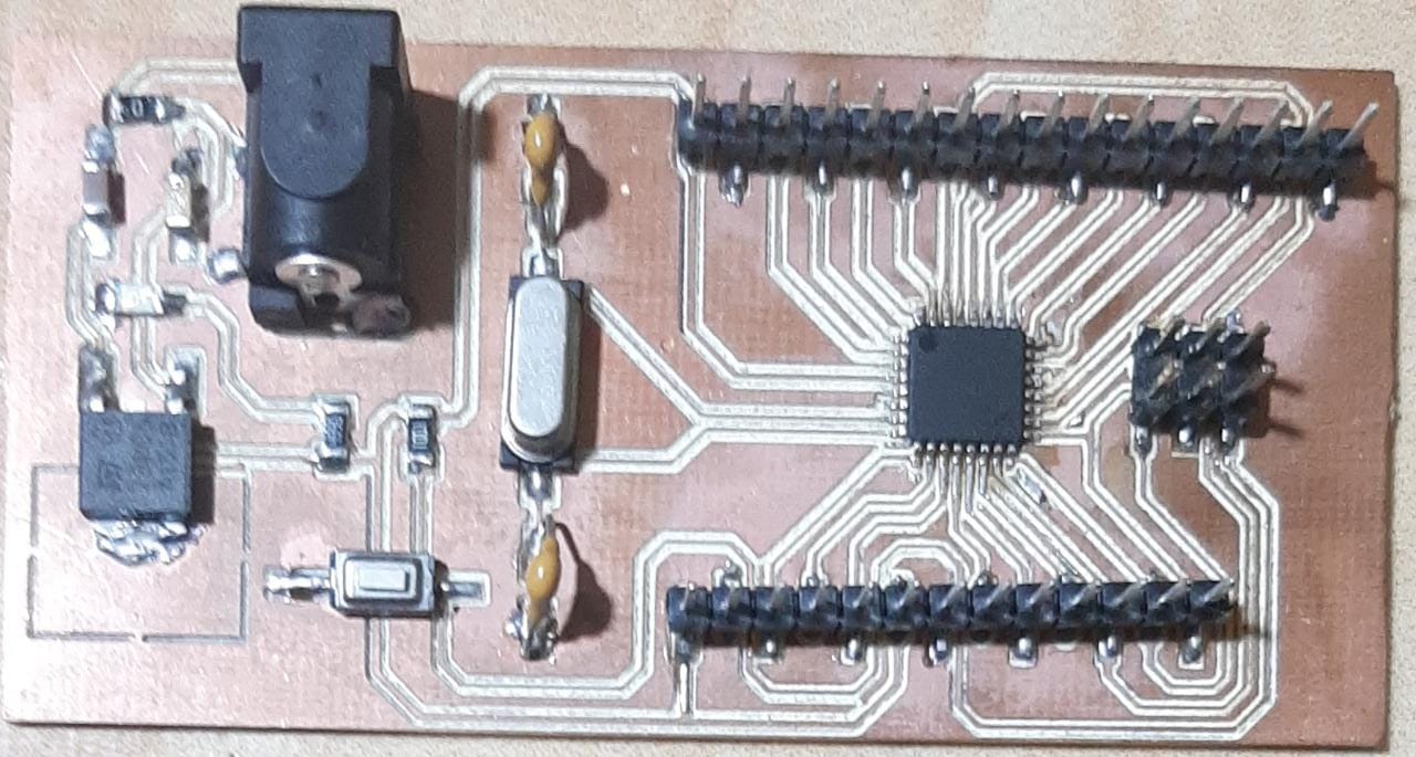
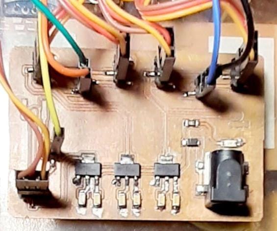
PCB with soldered components y ATmega328p microcontroller.
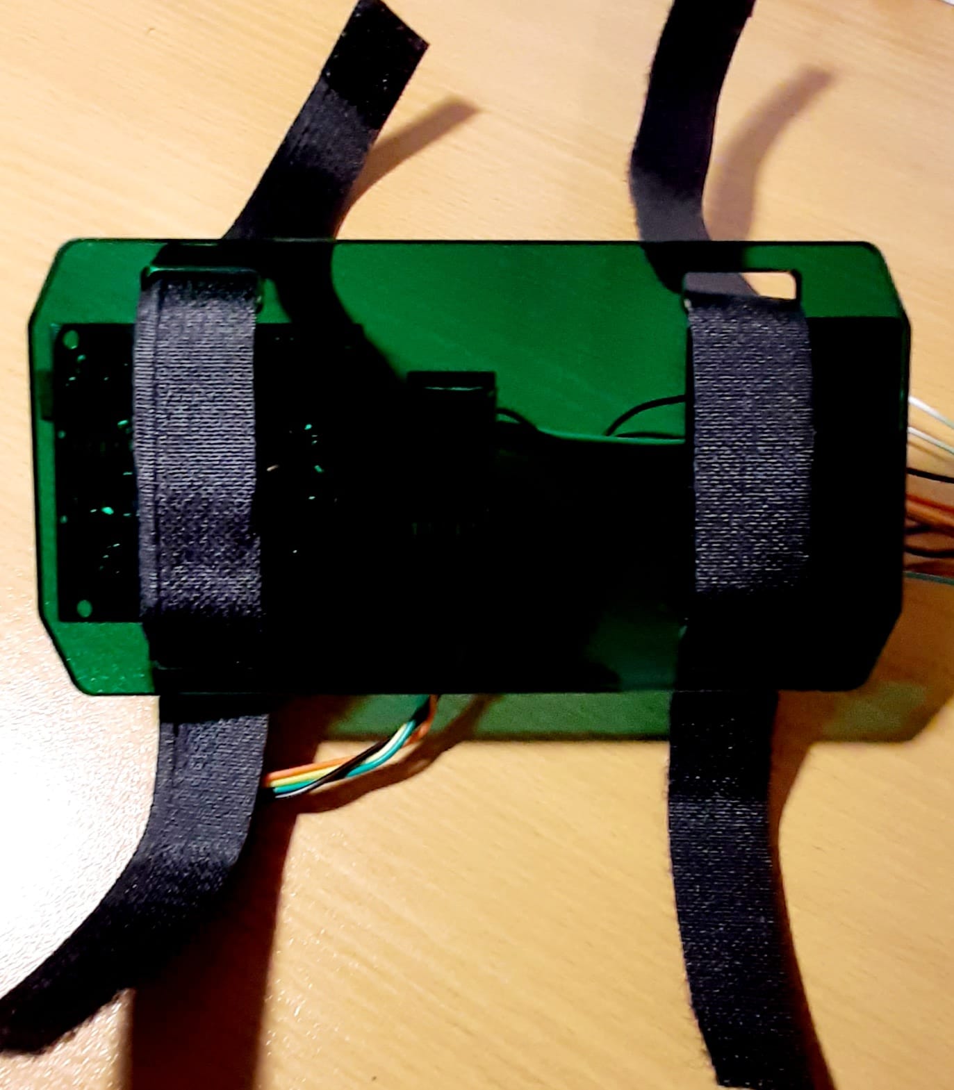
PCB with soldered components to connect the sensors.
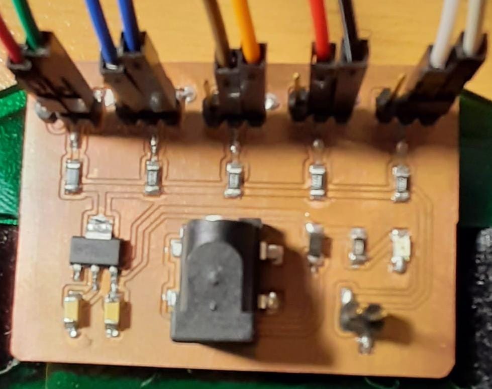
PCB with soldered components to connect the servomotors.
Embedded Programming
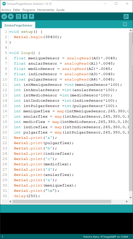
Program for the Emitter microcontroller.
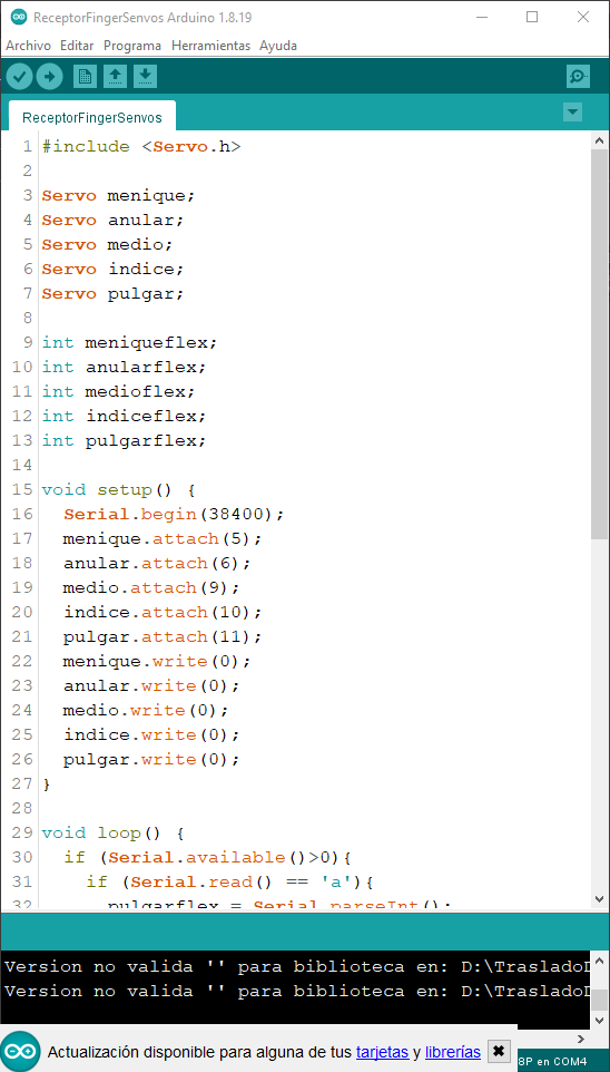
Program for the Receiver microcontroller.
I used Input Devices and Output Devices
The Input Devices that I used were flexible resistors, these vary their resistance according to the degree of flexion of the sensor.
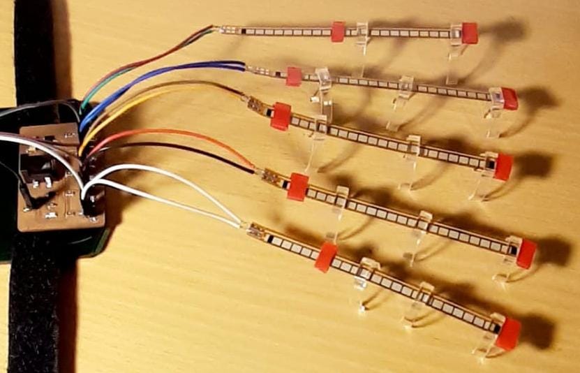
Flexible sensors attached to its PCB.
As Output Devices I used 5 microservos, one for each finger.
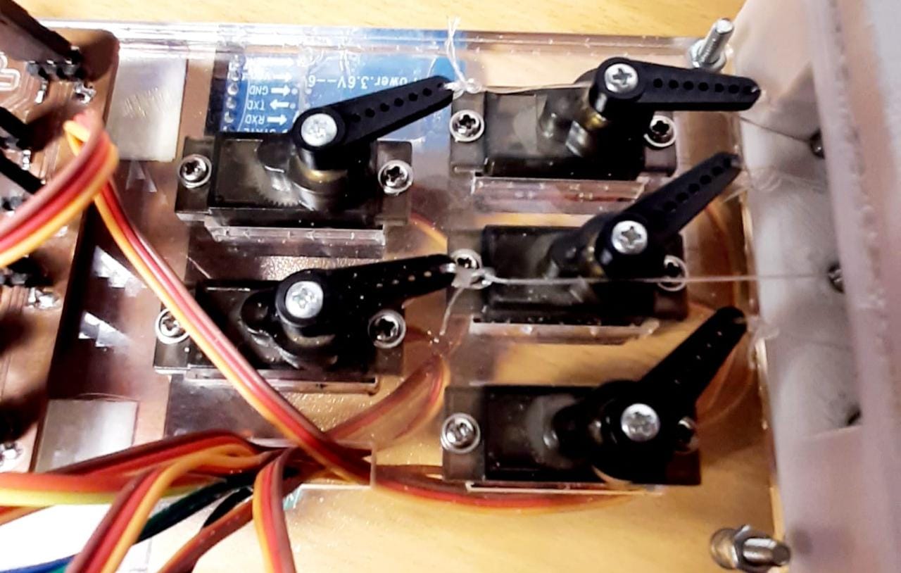
Hand-mounted micro servo motors.
I used Networking and Communications .
I used a master-slave Wireless Network configuration, two Bluetooths HC-05 were used.
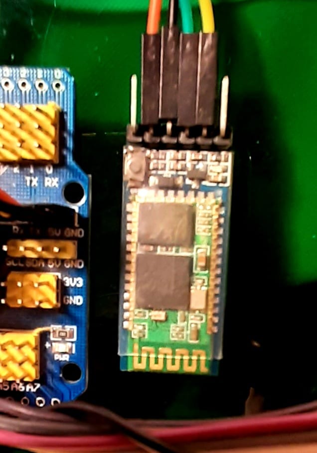
HC-05 bluetooth module configured as MASTER.
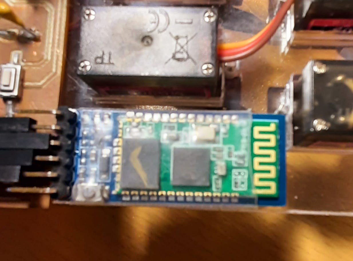
HC-05 bluetooth module configured as SLAVE.
Summary Slide
Sumary Slide
Video Clip
Project presentation Video
Licence

This work is under a Creative Commons Attribution 4.0 International License.