12. Mechanical design, machine design
Our Team
My team was made up as follows:
- Ulises who is my instructor
- Juan, student Fabacademy 2022
Ulises first carried out the search for the data sheets of the components to be used, such as electrical characteristics, mechanical dimensions, modes of operation and in the final part he was in charge of the assembly and function test of the system.
I, Juan, first made the design of the structure considering the mechanical dimensions of the selected components, then I made the design of the printed circuits considering the electrical characteristics of each component and finally I developed the control programs in manual and automatic mode, of course I also participated in the verification of operation.
Group Work Link
Here Start my Individual Work
Mechanical Design (part 1 of 2)
Design a machine that includes mechanism + actuation + automation + application
- Work schedule
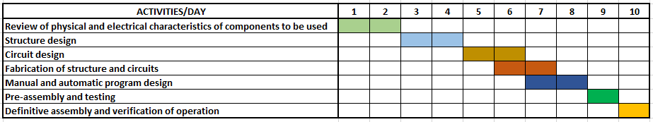
Full cycle for our project.
Mechanical Design
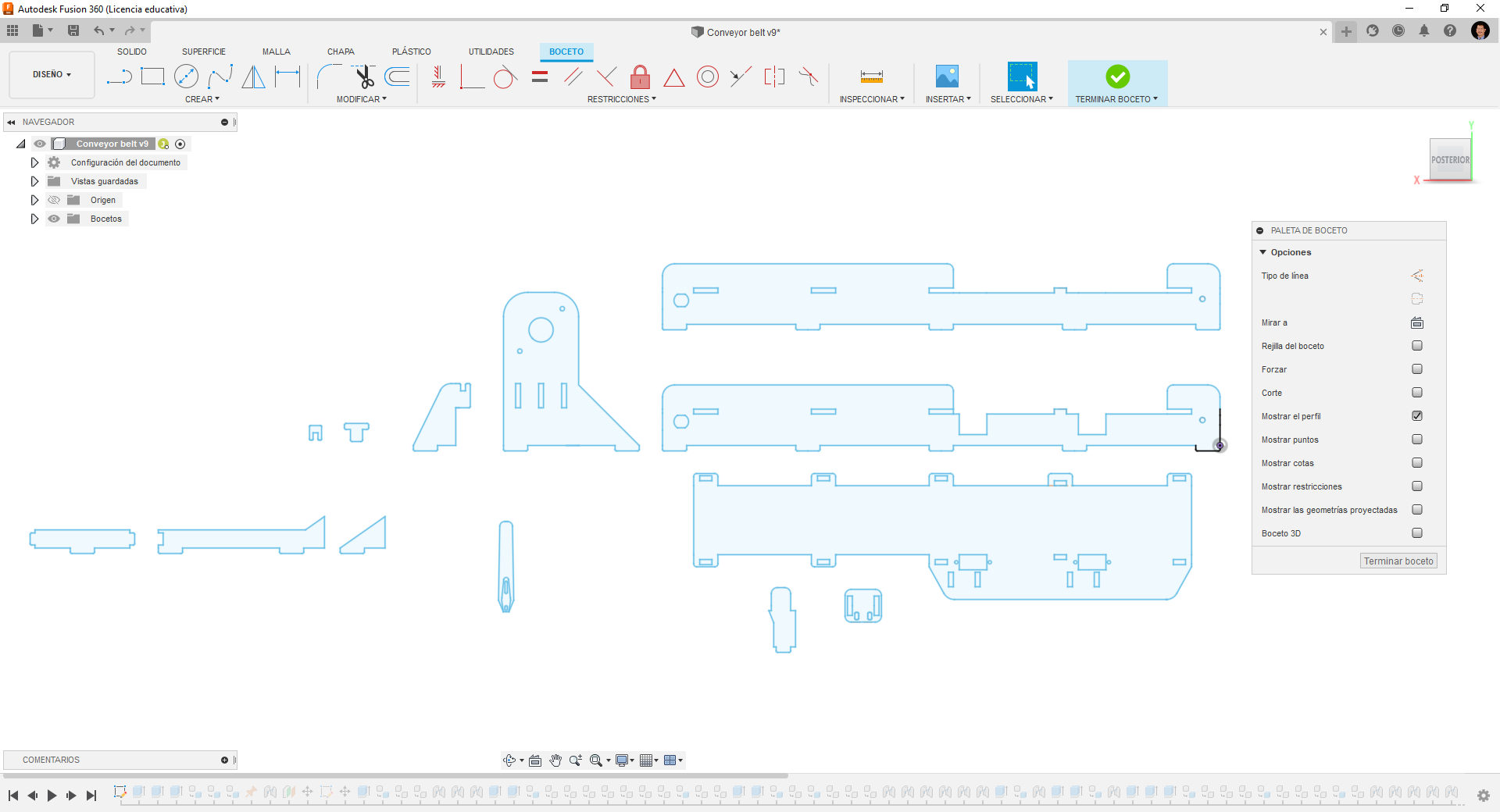
Conveyor sketch of all parts in FUSION 360
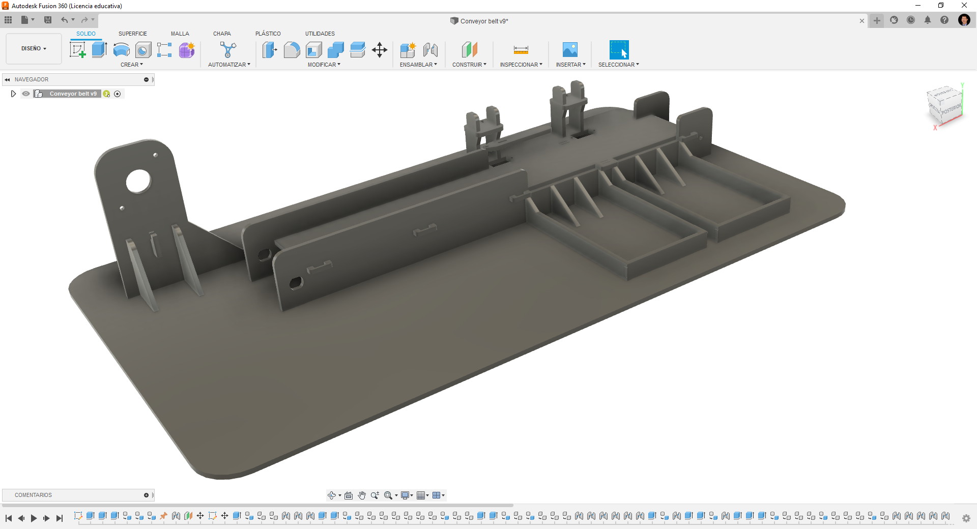
Assembly of parts in FUSION 360
Actuators
- Stepper Motor
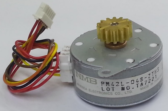
View of the stepper motor model PM42L-048
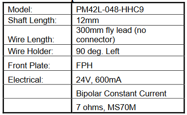
Specifications
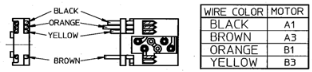
Wire color code
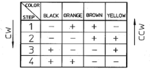
Switching sequence

Stepper Motor Mount
- Servo Motors
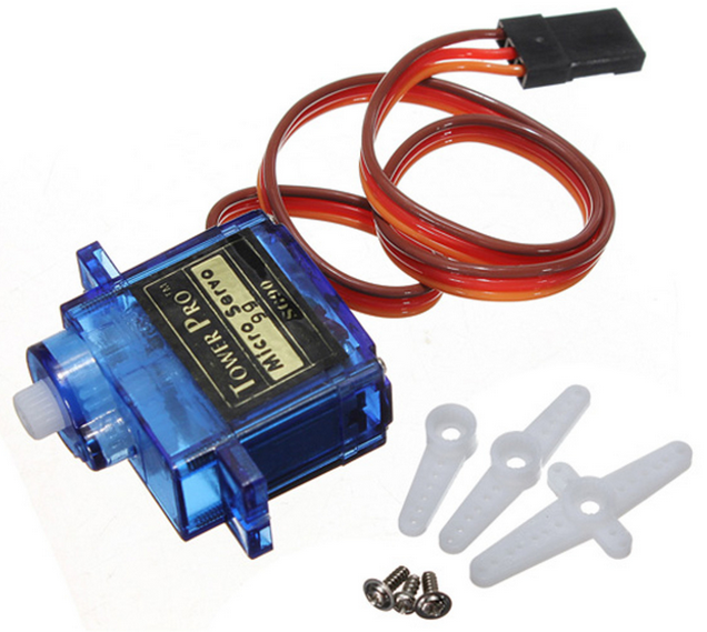
View of the servo motor SG90
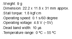
Specifications
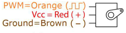
Wire color code
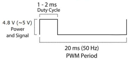
Control signal. Position “0” (1.5ms pulse) is middle, “90” (~2ms pulse) is middle, fully clockwise, “-90” (~1ms pulse) is fully on the left.
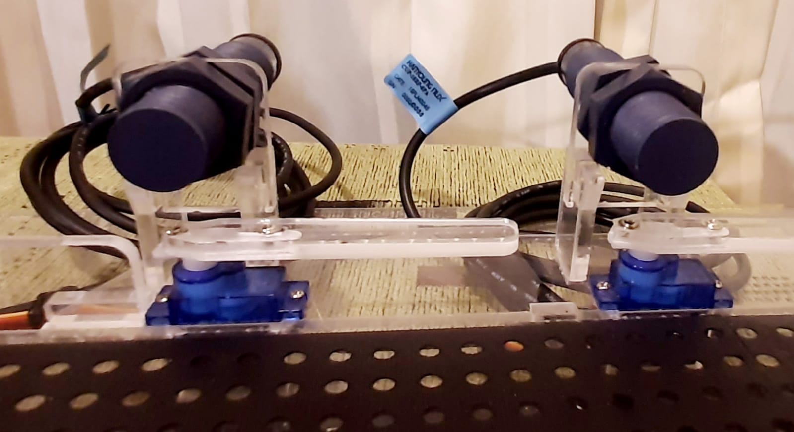
Mounting Servo Motors
Sensors and Matching Circuits
- Capacitive proximity sensor

View of the CUP-18RP-8PA capacitive proximity sensor

The sensor code indicates that it is a plastic encapsulated 18mm sensor with 8mm sensing distance with normally open collector PNP output signal
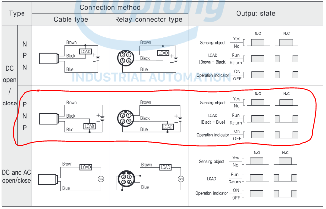
Connection diagram

Mounting of sensors
- Signal Adapter Circuit Design
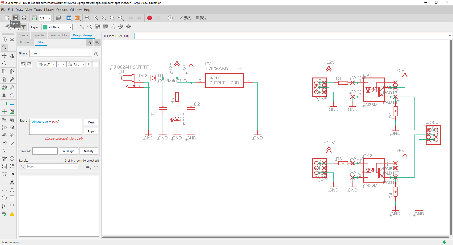
Schematic circuit of the design to adapt the signal of industrial sensors to 5 Vdc en EAGLE
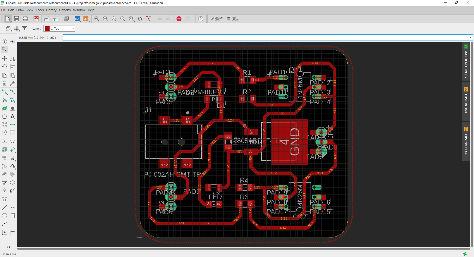
Design of the PCB of the signal adaptation circuit en EAGLE.
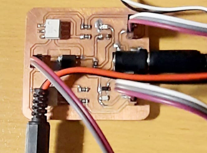
Signal matching PCB with components and connections.
- Motor Drive L298D
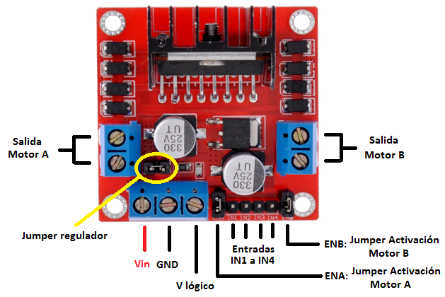
General description of the motor driver connection terminals
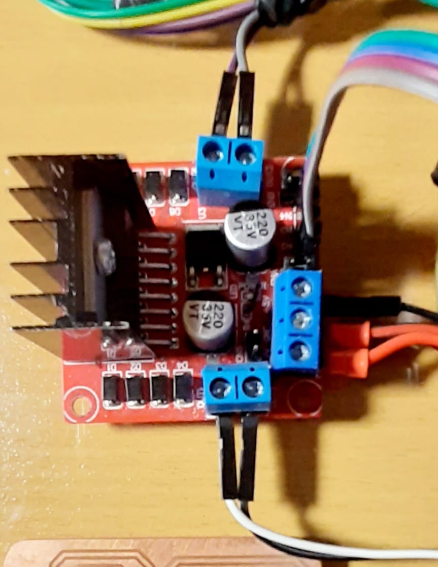
Motor driver with conections
- Power Supply DC 12Vdc
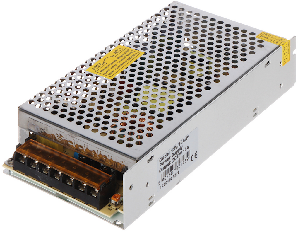
General view of the power supply
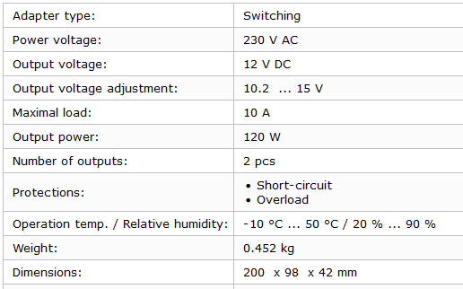
Specifications Power Supply
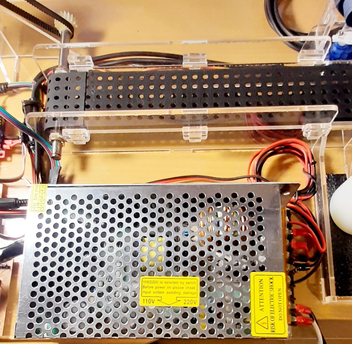
Power supply mounting
- Other Circuits
I used the same circuits that I used in Electronic Design assignment, these are microcontroller and button boards. Could reviw this link Electronics design
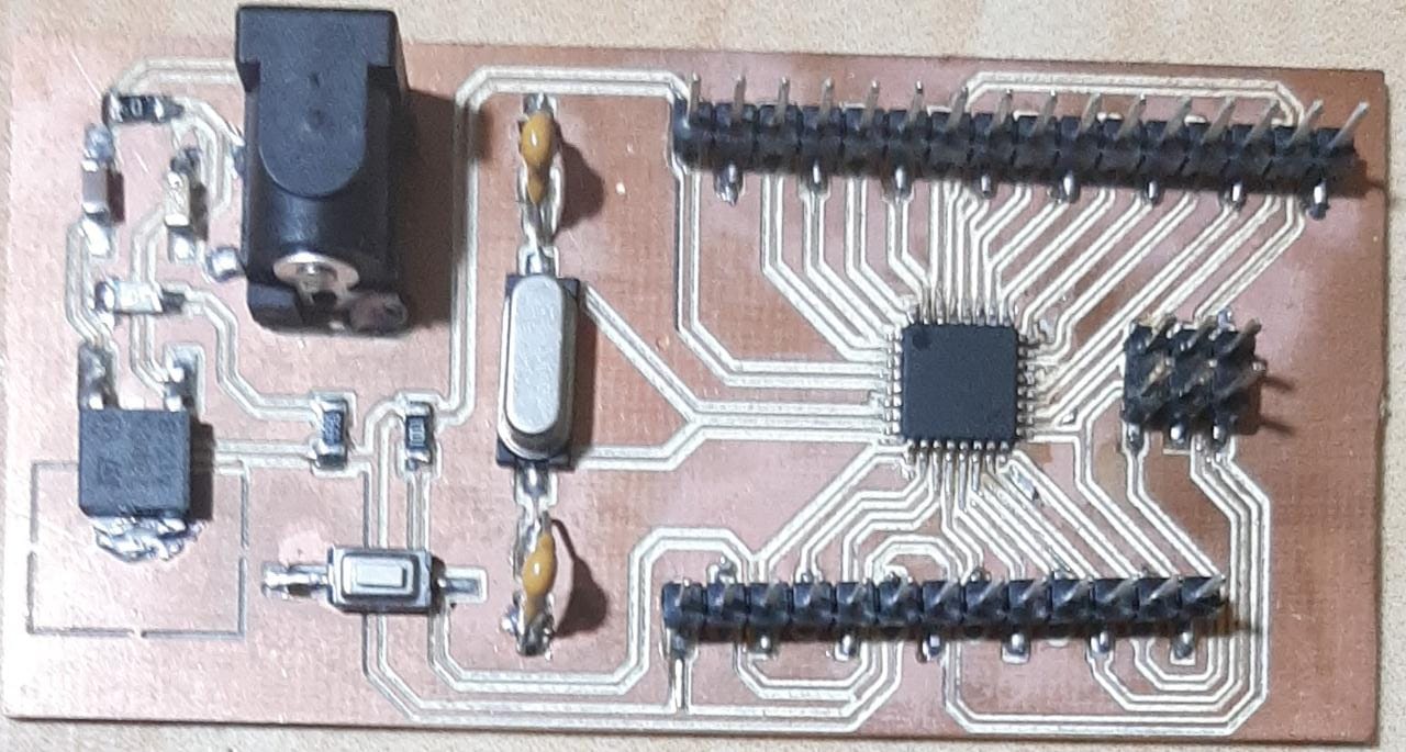
Microcontroller Board
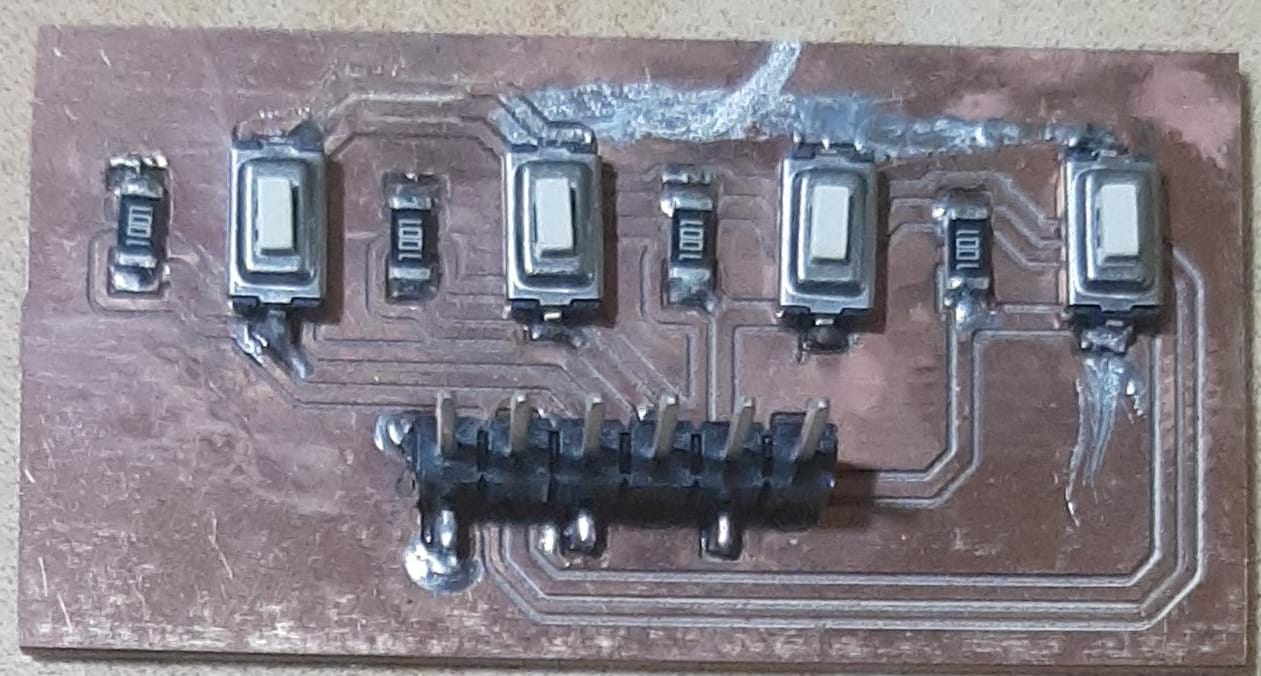
Button Board
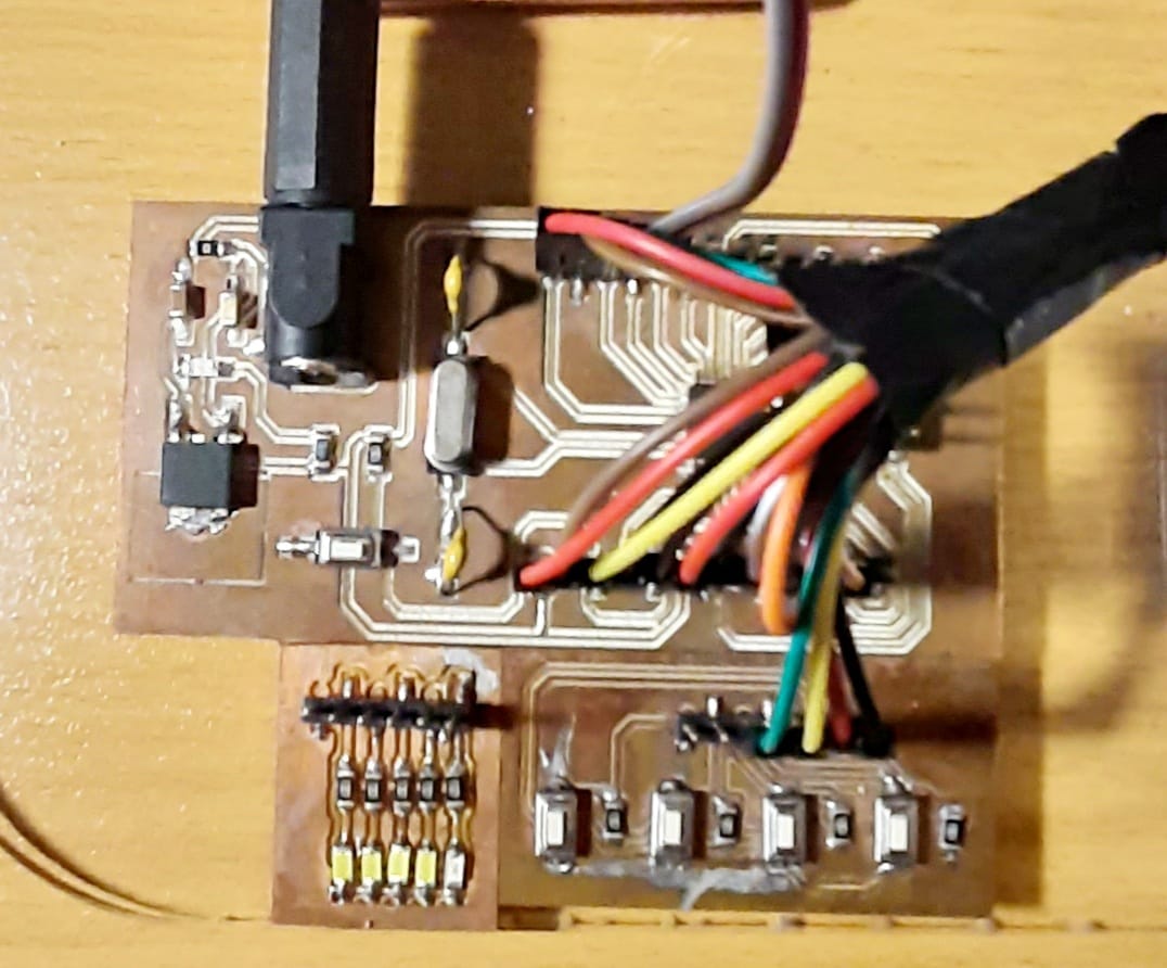
Microcontroller and Button Board Mounting
Build the mechanical parts and operate it manually.
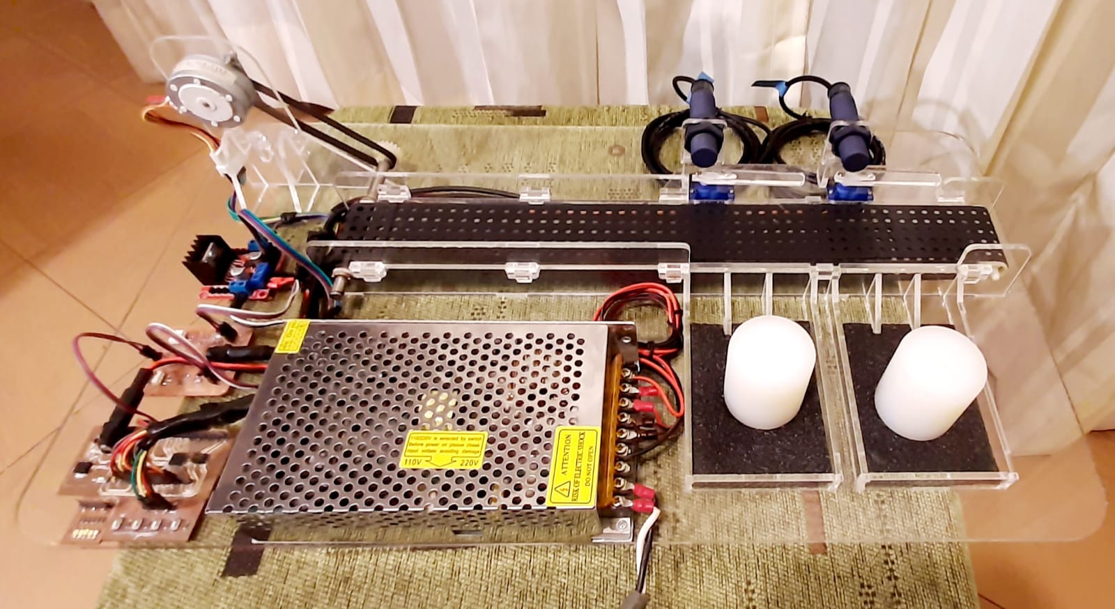
Conveyor belt assembled and with the assembly of sensors, actuators and electronic circuits
Machine Design (part 2 of 2)
Actuate and automate your machine.
The conveyor belt has two operating modes, manual mode and automatic mode:
Manual mode: the direction of the belt is controlled by two buttons, one for forward and one for reverse. If no button is pressed, the tape remains stopped. In this mode the sensors are inactive, so we must continue pressing the forward button until the object reaches the desired position, servomotor 1 or servomotor 2, to remove the objects that are on the belt we must press the corresponding button to the position that the object is inside, this activates the servo motor and the object is pushed towards the corresponding cubicle.
Manual operation of the conveyor belt
Automatic Mode: The system has a START button and another STOP button, to start the process we press the START button, then the belt advances and when it reaches the first sensor it stops so that the servomotor of said position is then activated. the band continues its advance, if another object is placed it will advance to the second sensor, there the band will stop and the second servomotor will be activated, depositing the object in the respective cubicle, this sequence is repeated until the STOP button is pressed.
Automatic operation of the conveyor belt
- Manual Control Code
#include <Servo.h>

Servo servoMetal;
Servo servoNoMetal;

int pos01 = 0;
int pos02 = 0;
int espera = 20;

// push button number
int ButtonStepForward = 2;
int ButtonStepReverse = 3;
int ButtonServoMetal = 4;
int ButtonServoNoMetal = 5;

// Stepper Motor Coil
int Coil01 = 6;
int Coil02 = 7;
int Coil03 = 8;
int Coil04 = 9;
// Servomotor Control
int ServoMetal = 10;
int ServoNoMetal = 11;


void setup() {
  // put your setup code here, to run once:

  pinMode(ButtonStepForward,INPUT);
  pinMode(ButtonStepReverse,INPUT);
  pinMode(ButtonServoMetal,INPUT);
  pinMode(ButtonServoNoMetal,INPUT);
  pinMode(Coil01,OUTPUT);
  pinMode(Coil02,OUTPUT);
  pinMode(Coil03,OUTPUT);
  pinMode(Coil04,OUTPUT);
  servoMetal.attach(ServoMetal);
  servoNoMetal.attach(ServoNoMetal);
}

void loop() {
  // put your main code here, to run repeatedly:
  if(!digitalRead(ButtonStepForward)){
    digitalWrite(Coil01,LOW);
    digitalWrite(Coil02,HIGH);
    digitalWrite(Coil03,HIGH);
    digitalWrite(Coil04,LOW);
    delay(espera);
    digitalWrite(Coil01,LOW);
    digitalWrite(Coil02,LOW);
    digitalWrite(Coil03,HIGH);
    digitalWrite(Coil04,HIGH);
    delay(espera);
    digitalWrite(Coil01,HIGH);
    digitalWrite(Coil02,LOW);
    digitalWrite(Coil03,LOW);
    digitalWrite(Coil04,HIGH);
    delay(espera);
    digitalWrite(Coil01,HIGH);
    digitalWrite(Coil02,HIGH);
    digitalWrite(Coil03,LOW);
    digitalWrite(Coil04,LOW);
    delay(espera);
  }
  if(!digitalRead(ButtonStepReverse)){
    digitalWrite(Coil01,HIGH);
    digitalWrite(Coil02,HIGH);
    digitalWrite(Coil03,LOW);
    digitalWrite(Coil04,LOW);
    delay(espera);
    digitalWrite(Coil01,HIGH);
    digitalWrite(Coil02,LOW);
    digitalWrite(Coil03,LOW);
    digitalWrite(Coil04,HIGH);
    delay(espera);
    digitalWrite(Coil01,LOW);
    digitalWrite(Coil02,LOW);
    digitalWrite(Coil03,HIGH);
    digitalWrite(Coil04,HIGH);
    delay(espera);
    digitalWrite(Coil01,LOW);
    digitalWrite(Coil02,HIGH);
    digitalWrite(Coil03,HIGH);
    digitalWrite(Coil04,LOW);
    delay(espera);
  }
  if(digitalRead(ButtonServoMetal)){
    for (pos01 = 90; pos01 >= 0; pos01 -= 1) {
      servoMetal.write(pos01);
      delay(15);
    }
    for (pos01 = 0; pos01 <= 90; pos01 += 1) {
      servoMetal.write(pos01);
      delay(15);
    }
  }
  if(digitalRead(ButtonServoNoMetal)){
    for (pos02 = 80; pos02 >= 0; pos02 -= 1) {
      servoNoMetal.write(pos02);
      delay(15);
    }
    for (pos02 = 0; pos02 <= 80; pos02 += 1) {
      servoNoMetal.write(pos02);
      delay(15);
    }
  }
}
- Automatic Control Code
#include <Servo.h>

Servo servo01;
Servo servo02;

int pos01 = 0;
int pos02 = 0;
int delayServos = 10;
int timeStepStepper = 18;
int stepStepper = 0;
int numberStepper = 1;
int tiempoActual = millis();
int tiempoAnterior = 0;
int tiempoposicion = 400;
int tiempo01 = 0;
int tiempo02 = 0;
boolean servo01Enable = false;
boolean servo02Enable = false;
boolean startEnable = false;

// push button number
int pinSensor01 = 2;
int pinSensor02 = 3;
int pinStartButton = 4;
int pinStopButton = 5;
//int autoHandButton = 4;
// Stepper Motor Coils
int Coil01 = 6;
int Coil02 = 7;
int Coil03 = 8;
int Coil04 = 9;
// Servomotor Control
int pinServo01 = 10;
int pinServo02 = 11;

void setup() {
  pinMode(pinSensor01,INPUT);
  pinMode(pinSensor02,INPUT);
  pinMode(pinStartButton,INPUT);
  pinMode(pinStopButton,INPUT);
  pinMode(Coil01,OUTPUT);
  pinMode(Coil02,OUTPUT);
  pinMode(Coil03,OUTPUT);
  pinMode(Coil04,OUTPUT);
  servo01.attach(pinServo01);
  servo02.attach(pinServo02);
}

void loop() {
  if (digitalRead(pinStartButton)&&!digitalRead(pinStopButton)){
    delay(150);
    servo01Enable = false;
    servo02Enable = false;
    startEnable = true;
    attachInterrupt(digitalPinToInterrupt(pinSensor01), servo01Action, FALLING);
    attachInterrupt(digitalPinToInterrupt(pinSensor02), servo02Action, FALLING);
  } else if (!digitalRead(pinStartButton)&&digitalRead(pinStopButton)){
    delay(150);
    startEnable = false;
    detachInterrupt(digitalPinToInterrupt(pinSensor01));
    detachInterrupt(digitalPinToInterrupt(pinSensor02));
    stepStepper = 0;
    numberStepper = 1;
    servo01Enable = false;
    servo02Enable = false;
    digitalWrite(Coil01,LOW);
    digitalWrite(Coil02,LOW);
    digitalWrite(Coil03,LOW);
    digitalWrite(Coil04,LOW);
  }
  if (startEnable){
    tiempoActual = millis();
    if (tiempoActual - tiempoAnterior >= timeStepStepper){
      tiempoAnterior = tiempoActual;
      conveyorForward();
    }
    if (servo01Enable && numberStepper == 1){//
      tiempo01 = millis();
      tiempo02 = tiempo01;
      while (tiempo02 - tiempo01 < tiempoposicion){
        tiempo02 = millis();
        tiempoActual = millis();
        if (tiempoActual - tiempoAnterior >= timeStepStepper){
          tiempoAnterior = tiempoActual;
          conveyorForward();
        }
      }
      for (pos01 = 90; pos01 >= 0; pos01 -= 1) {
        servo01.write(pos01);
        delay(delayServos);
      }
      for (pos01 = 0; pos01 <= 90; pos01 += 1) {
        servo01.write(pos01);
        delay(delayServos);
      }
      servo01Enable = false;
      numberStepper = 2;
    }
    if (servo02Enable && numberStepper == 2){
      tiempo01 = millis();
      tiempo02 = tiempo01;
      while (tiempo02 - tiempo01 < tiempoposicion){
        tiempo02 = millis();
        tiempoActual = millis();
        if (tiempoActual - tiempoAnterior >= timeStepStepper){
          tiempoAnterior = tiempoActual;
          conveyorForward();
        }
      }
      for (pos02 = 80; pos02 >= 0; pos02 -= 1) {
        servo02.write(pos02);
        delay(delayServos);
      }
      for (pos02 = 0; pos02 <= 80; pos02 += 1) {
        servo02.write(pos02);
        delay(delayServos);
      }
      numberStepper = 1;
      servo02Enable = false;
      servo01Enable = false;
    }
  }
}
void servo01Action(){
  servo01Enable = true;
}
void servo02Action(){
  servo02Enable = true;
}
void conveyorForward(){
  switch (stepStepper) {
    case 0:
      digitalWrite(Coil01,HIGH);
      digitalWrite(Coil02,HIGH);
      digitalWrite(Coil03,LOW);
      digitalWrite(Coil04,LOW);
      stepStepper++;
      break;
    case 1:
      digitalWrite(Coil01,HIGH);
      digitalWrite(Coil02,LOW);
      digitalWrite(Coil03,LOW);
      digitalWrite(Coil04,HIGH);
      stepStepper++;
      break;
    case 2:
      digitalWrite(Coil01,LOW);
      digitalWrite(Coil02,LOW);
      digitalWrite(Coil03,HIGH);
      digitalWrite(Coil04,HIGH);
      stepStepper++;
      break;
    case 3:
      digitalWrite(Coil01,LOW);
      digitalWrite(Coil02,HIGH);
      digitalWrite(Coil03,HIGH);
      digitalWrite(Coil04,LOW);
      stepStepper = 0;
      break;
    default:
      stepStepper = 0;
      break;
  }
}
My individual contribution.
In my case I worked alone, so the design of the strap structure, the sequences of the manual and automatic processes and almost all the card designs are mine.
For the mechanical design it was necessary to review the dimensions indicated in the manuals and even physically verify them.
For the design of the programs it was necessary to understand the operating modes of the devices to be connected.
For the design of the printed circuits it was necessary to review the electrical characteristics of sensors and actuators to adapt said signals to those of the microcontroller.
Useful links
- Datasheet Stepper
- Datasheet Servo
- Datasheet Sensor
- Operation Motor Drive L298N
- Microcontroller and Button Board