4. Computer controlled cutting
Group assignment:
Characterize your lasercutter’s focus, power, speed, rate, kerf, joint clearance and types.
Focus Characterization
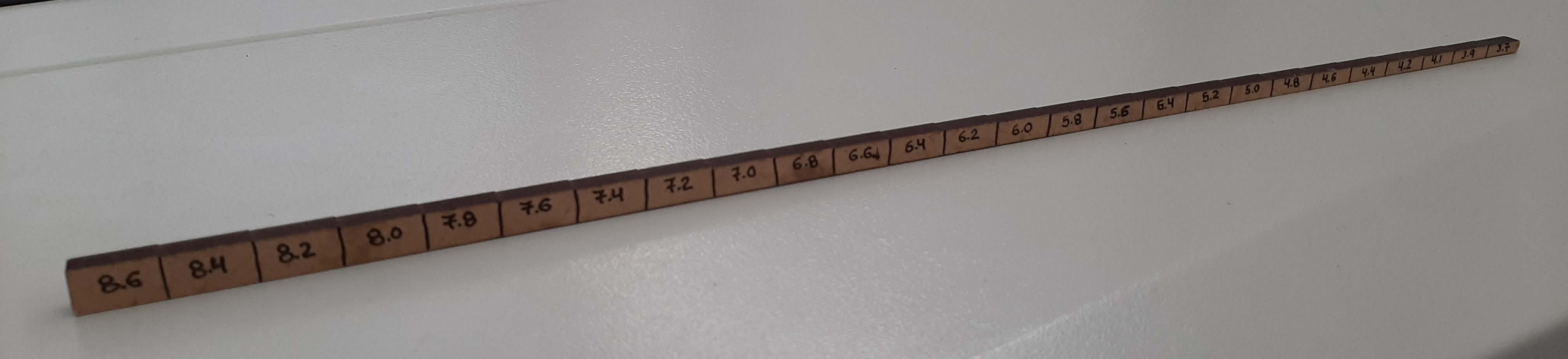
Focus height gauge
Focus Height Adjustment Procedure
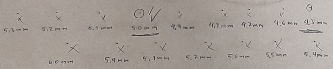
Evaluation of Results, top face
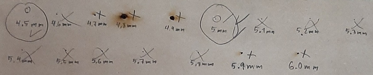
Evaluation of Results, back face
According to the focus test, we noticed that at the distance of 4.5mm and 5mm the hole has the most rounded shape and smaller diameter on both the top and back faces, after comparing both holes, we prefer the 4.5mm one because it is the smallest diameter.
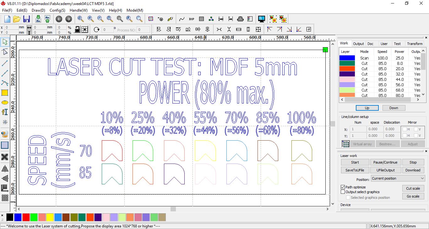
Power and Speed to Cut Characterization
We work with the RDworks program, we differentiate each speed or power characteristic with the selection of a color.
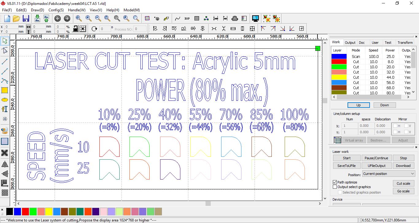
Design for cutting ACRYLIC with speeds of 10 mm/s and 25 mm/s at powers between 10% and 100%
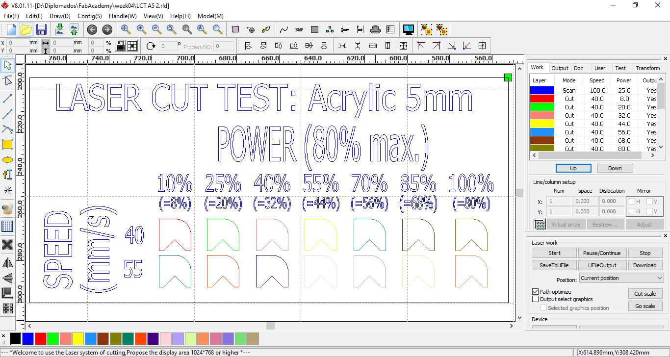
Design for cutting ACRYLIC with speeds of 40 mm/s and 55 mm/s at powers between 10% and 100%
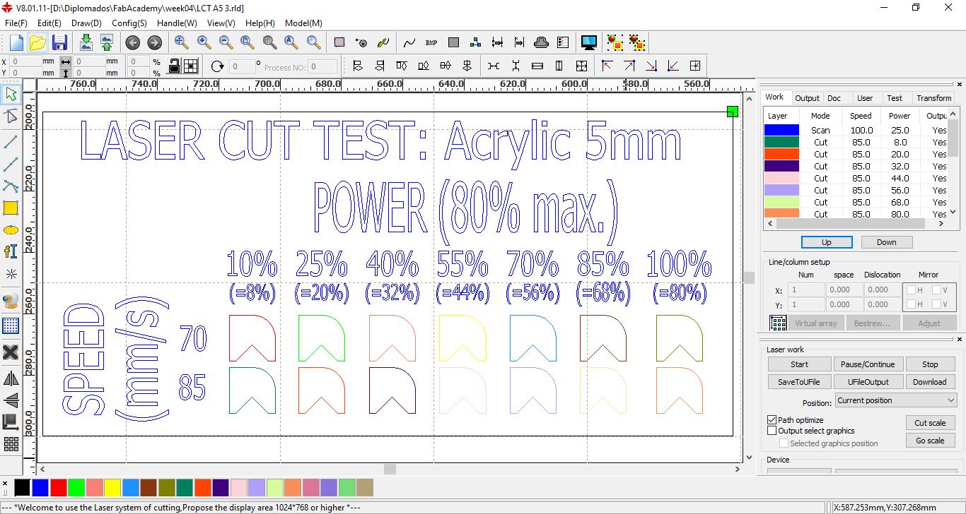
Design for cutting ACRYLIC with speeds of 70 mm/s and 85 mm/s at powers between 10% and 100%

Design for cutting ACRYLIC with speeds of 100 mm/s and 115 mm/s at powers between 10% and 100%
Speed and Power Test to Acrylic 5 mm part 1
Speed and Power Test to Acrylic 5 mm part 2
Speed and Power Test to Acrylic 5 mm part 3
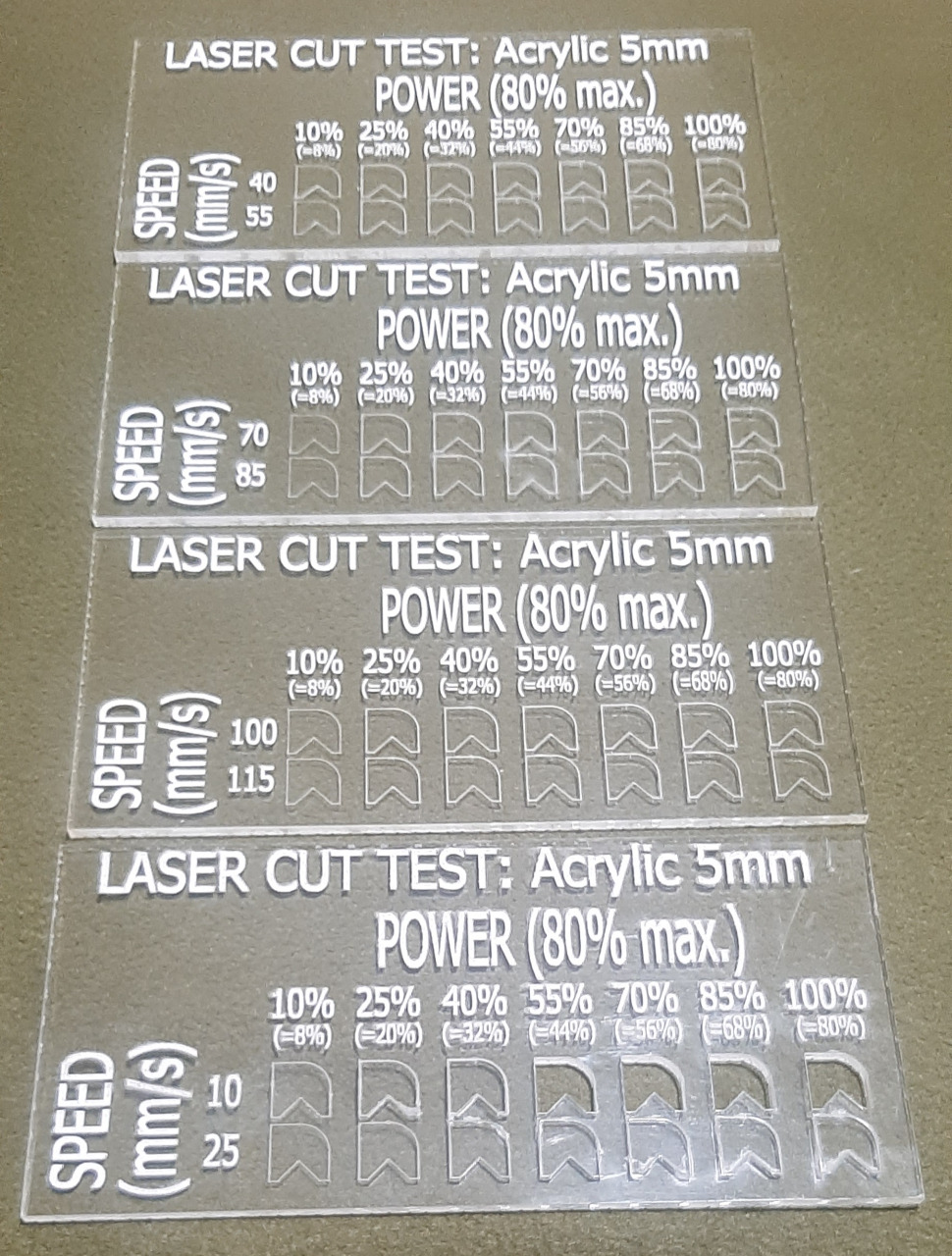
Results of the ACRYLIC test, it is observed that the cut is achieved with the lowest speed, which is 10 mm/s with powers greater than 50%.
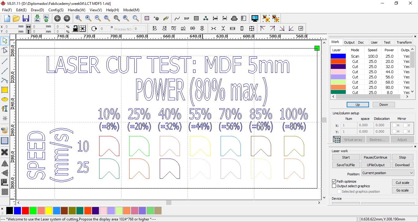
Design for cutting MDF with speeds of 10 mm/s and 25 mm/s at powers between 10% and 100%

Design for cutting MDF with speeds of 40 mm/s and 55 mm/s at powers between 10% and 100%
Design for cutting MDF with speeds of 70 mm/s and 85 mm/s at powers between 10% and 100%

Design for cutting MDF with speeds of 100 mm/s and 115 mm/s at powers between 10% and 100%
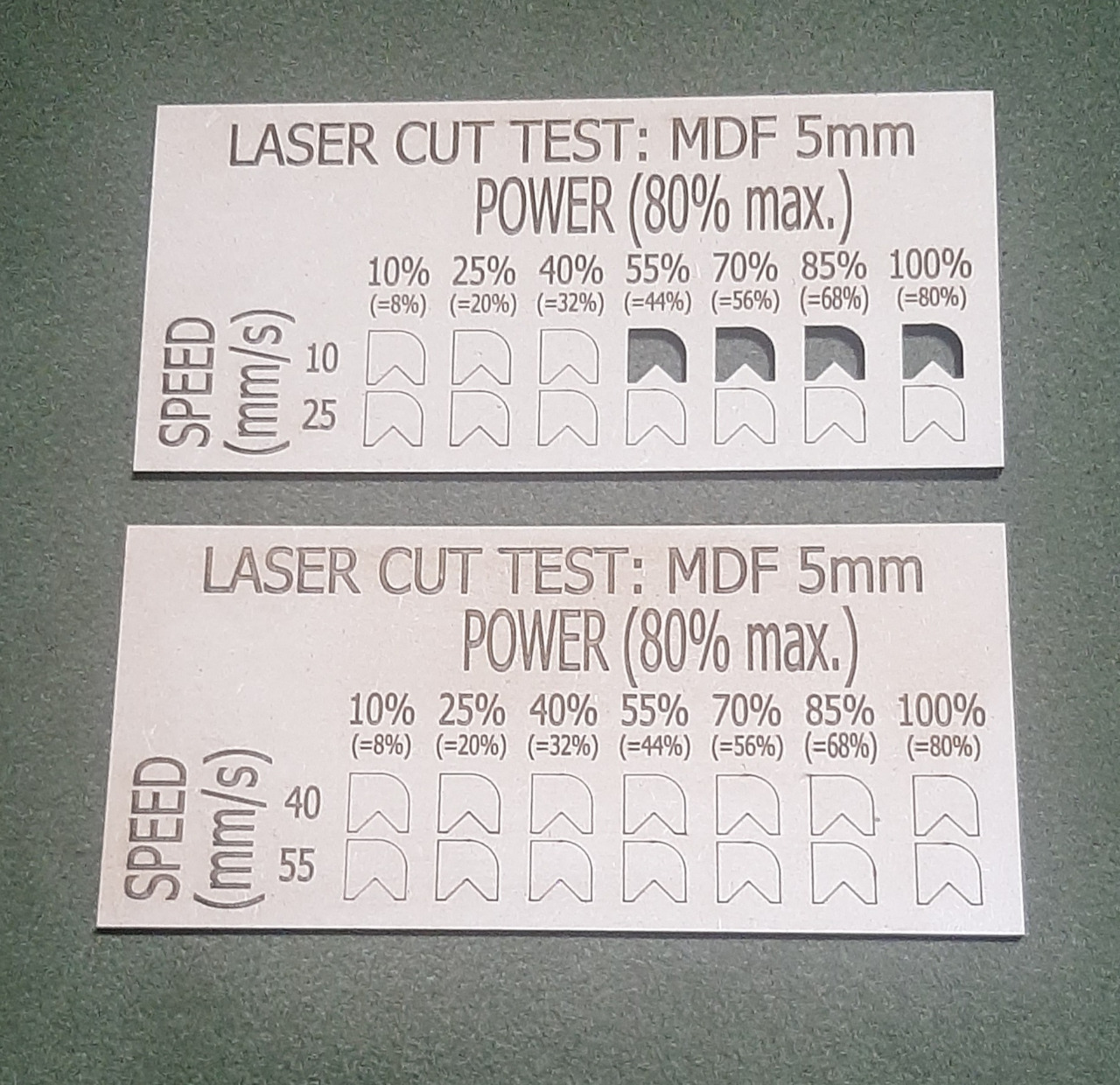
Results of the MDF test, it is observed that the cut is achieved with the lowest speed, which is 10 mm/s with powers greater than 50%.
Individual assignment:
Cut something on the vinylcutter.
The main difficulty I had was with the vinyl cutter, when exporting the cut lines to the CutStudio software, these lines lose precision, whether the cut lines are generated by CutStudio, jpg files, or imported directly as lines, eps files.
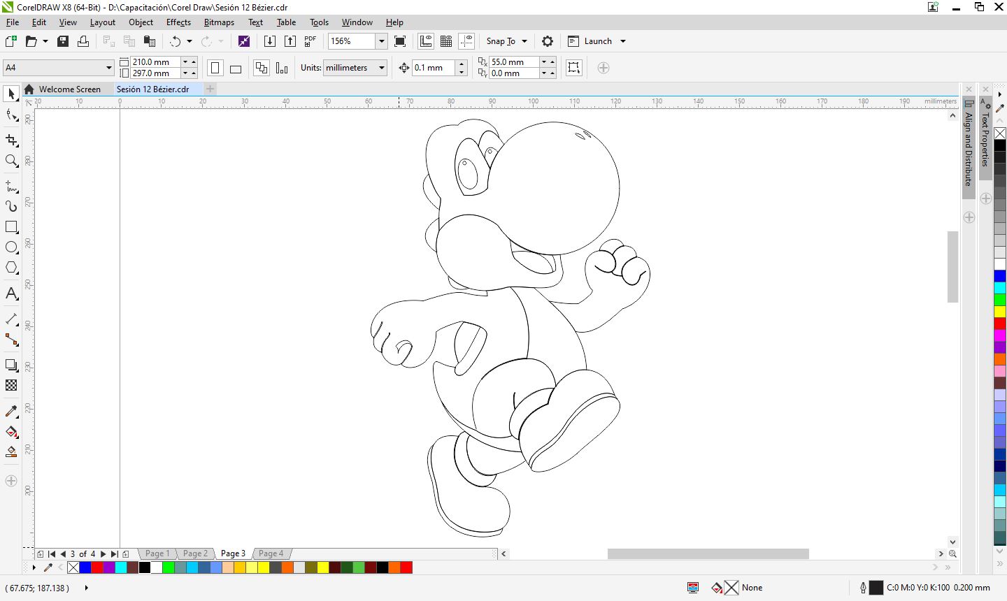
- I made my design, this was done in CorelDraw.
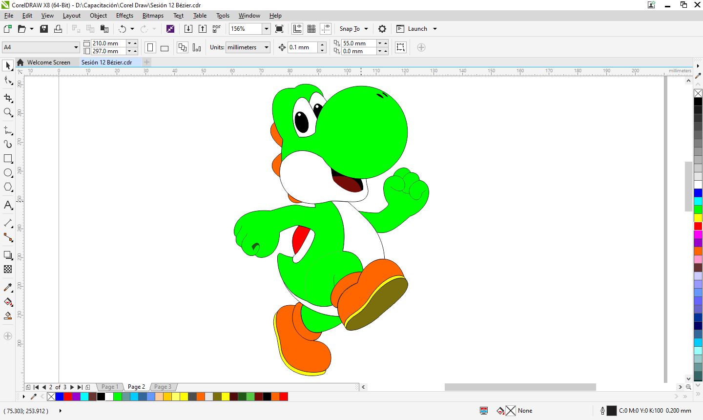
- I separated the pieces according to color.
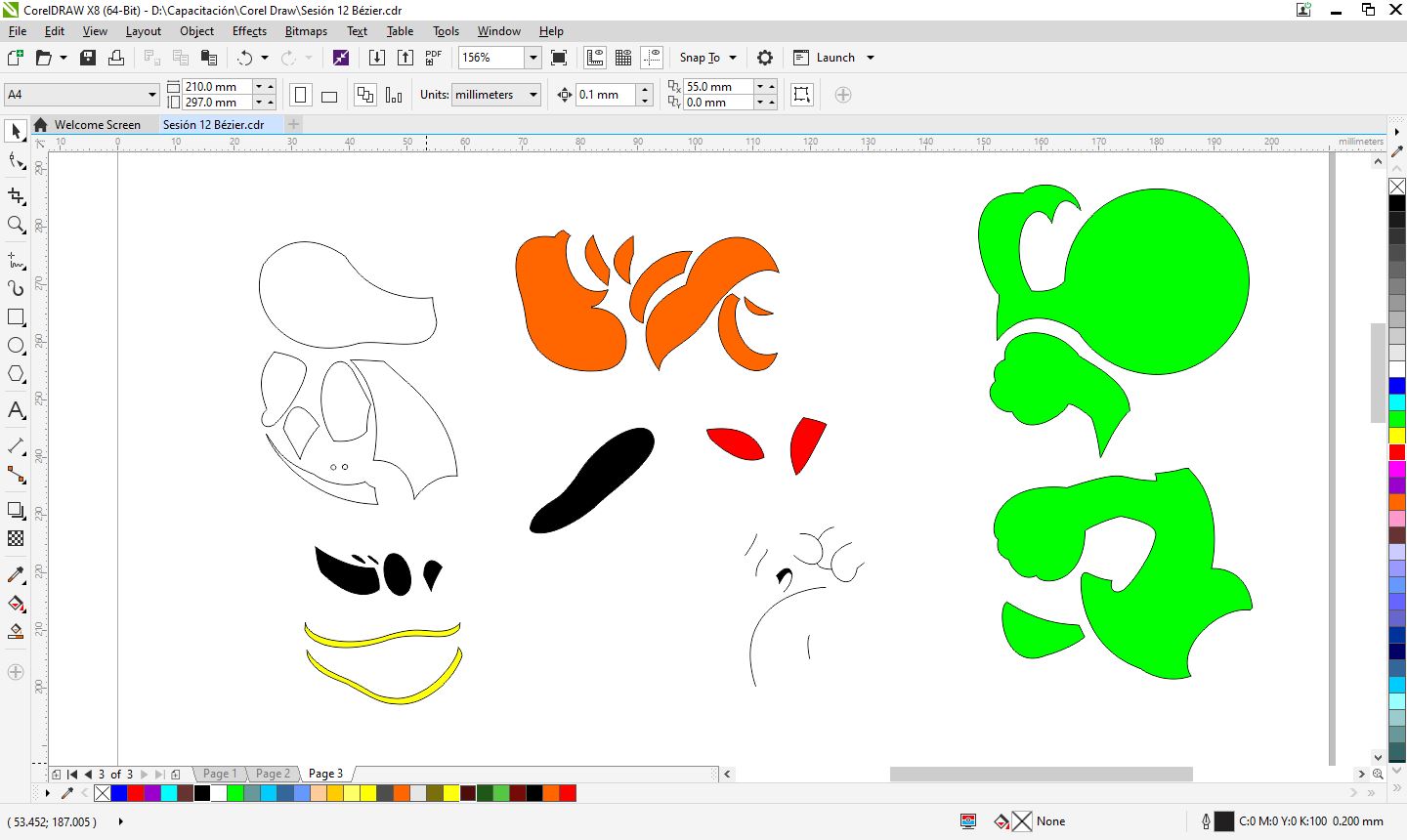
- I exported to a format that can be opened with CutStudio, in my case it was jpg or eps, and I got the cutting lines.
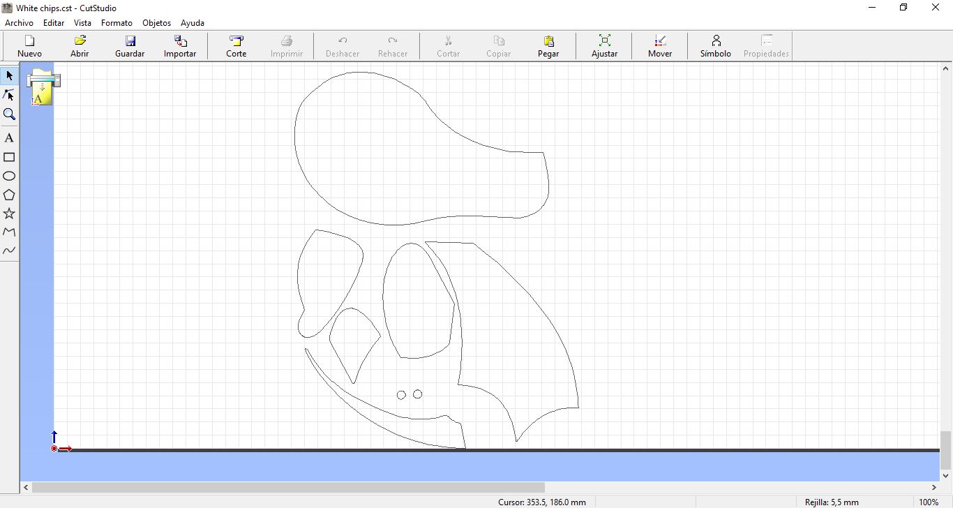
Profile in white color in CutStudio Program
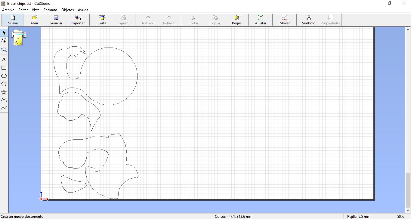
Profile in green color in CutStudio Program
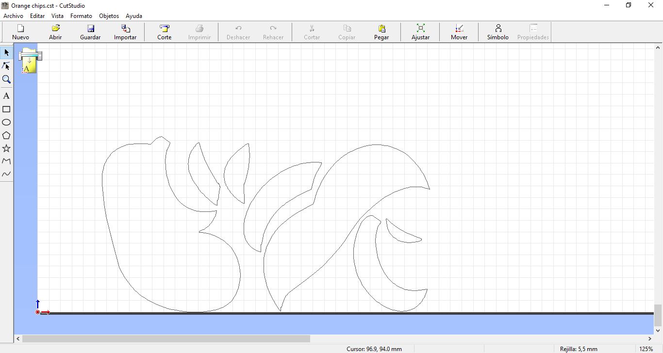
Profile in white orange in CutStudio Program
Export process to CutStudio Program
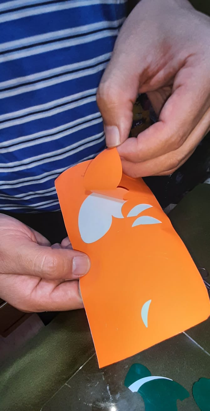
Peeling off each piece.
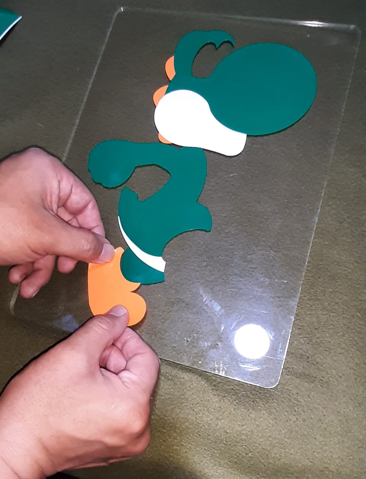
Assembling pieces on the acrylic board.
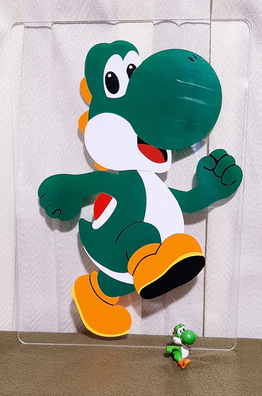
Showing Yoshi’s picture.

I am happy with my Assignment.
Design, lasercut, and document a parametric construction kit, accounting for the lasercutter kerf, which can be assembled in multiple ways, and for extra credit include elements that aren’t flat.
First, I designed a test cut for my material, I used 2 mm thick cardboard.
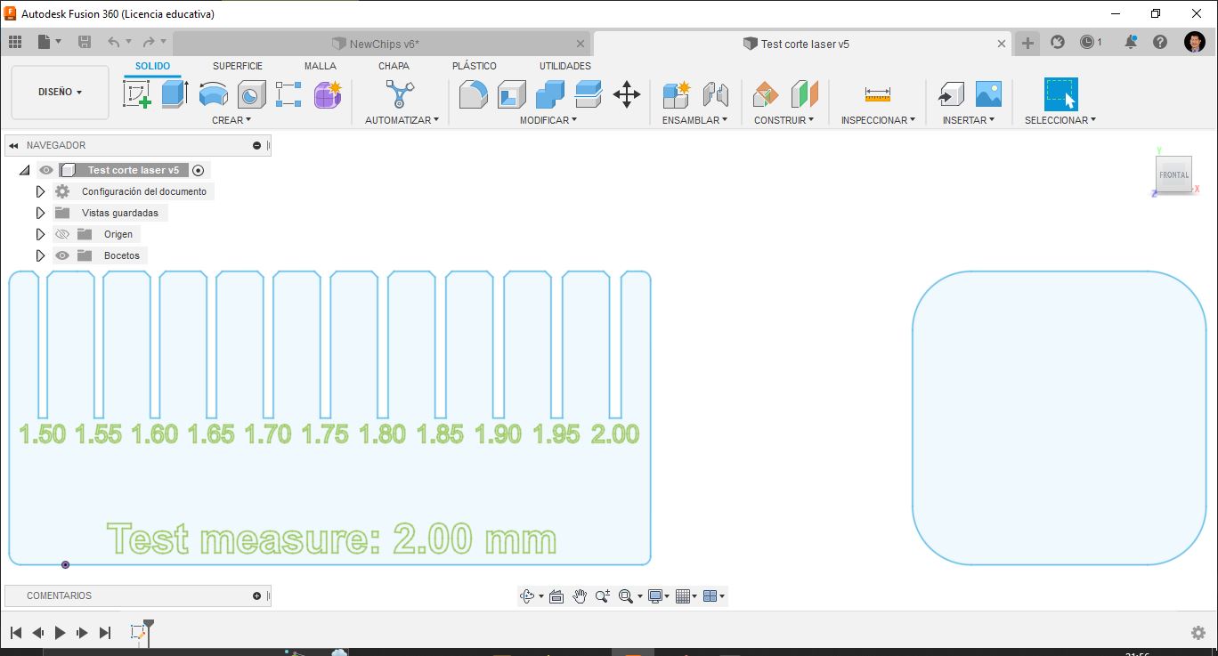
Test cut final design for 2mm thick cardboard in Fusion 360.
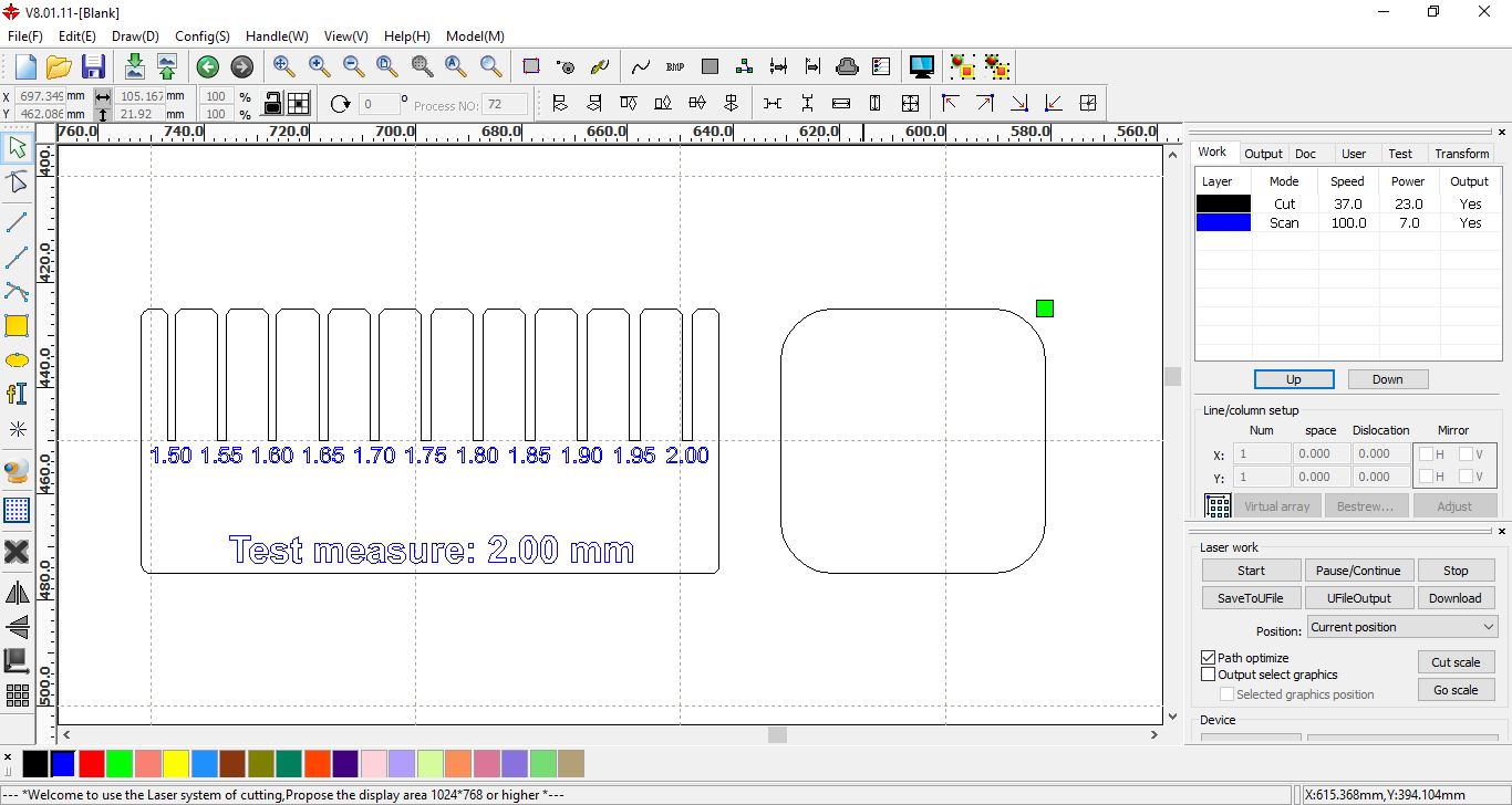
Cut laser configuration en RDWorks.
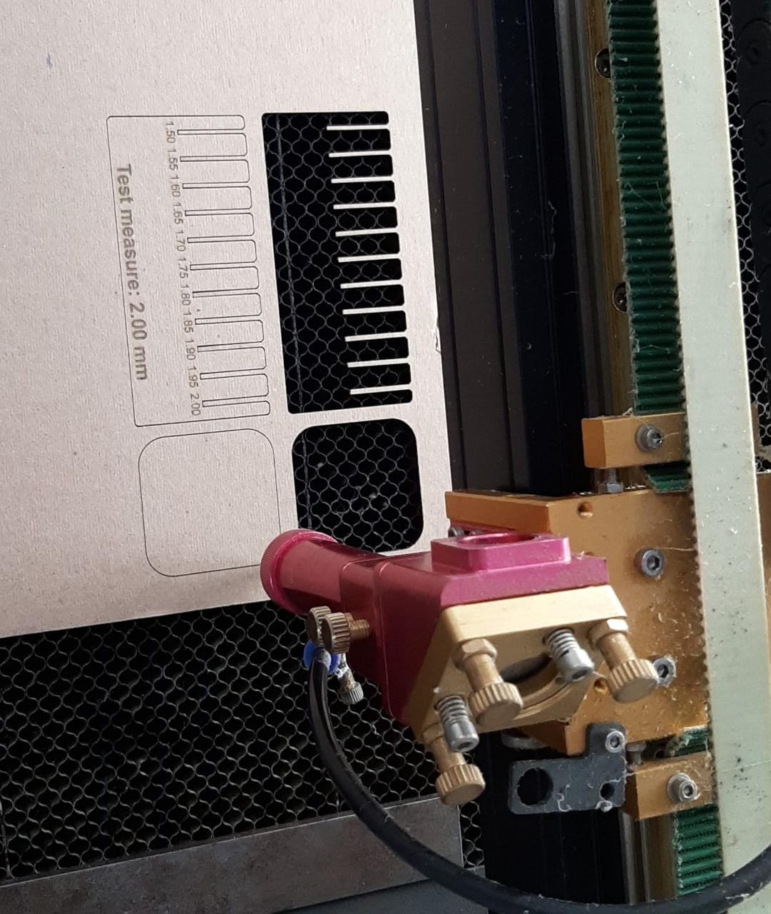
Test cut second fabrication, the first failed.
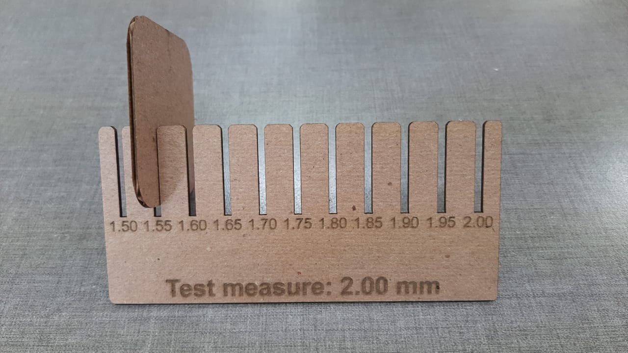
Proof adjust verification. In my case, for 2mm thick cardboard we get a good fit at 1.55mm cutting thickness.
Second, I designed my pieces.
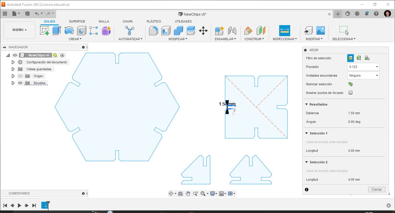
Pieces design in Fusion 360.
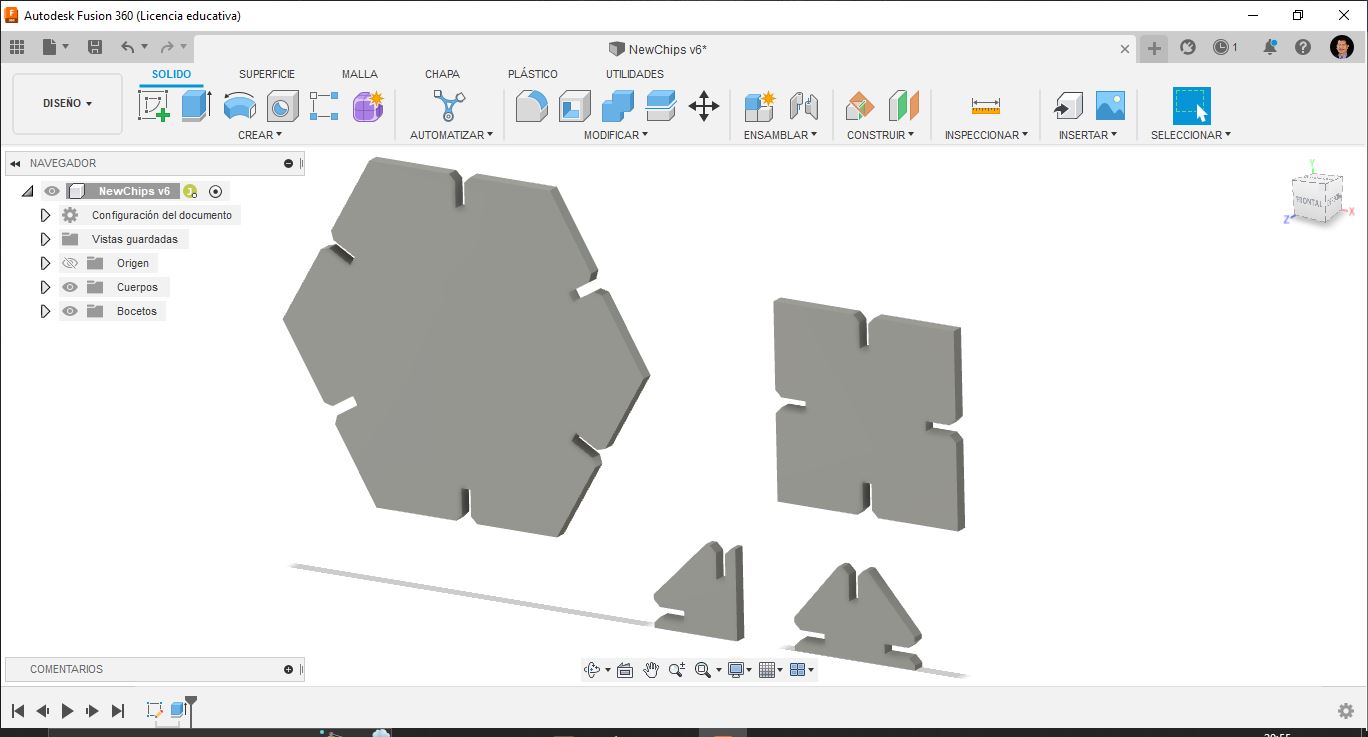
Pieces view in 3D in Fusion 360.
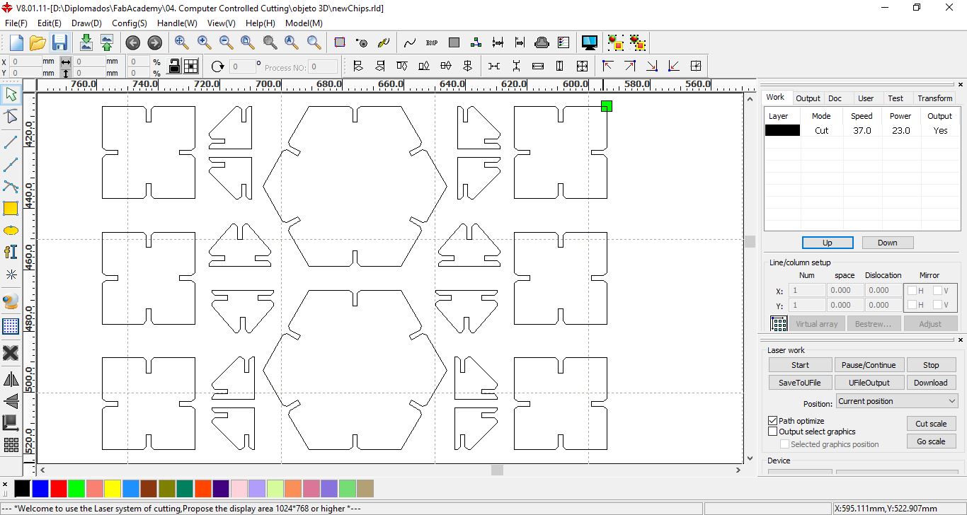
Cut laser configuration en RDWorks.
Modifying parameters without design deformation
So that the designed object does not lose or deform its shape, it is necessary to build it by applying constraints, with this we ensure that when modifying the dimensions of the object it retains its shape.
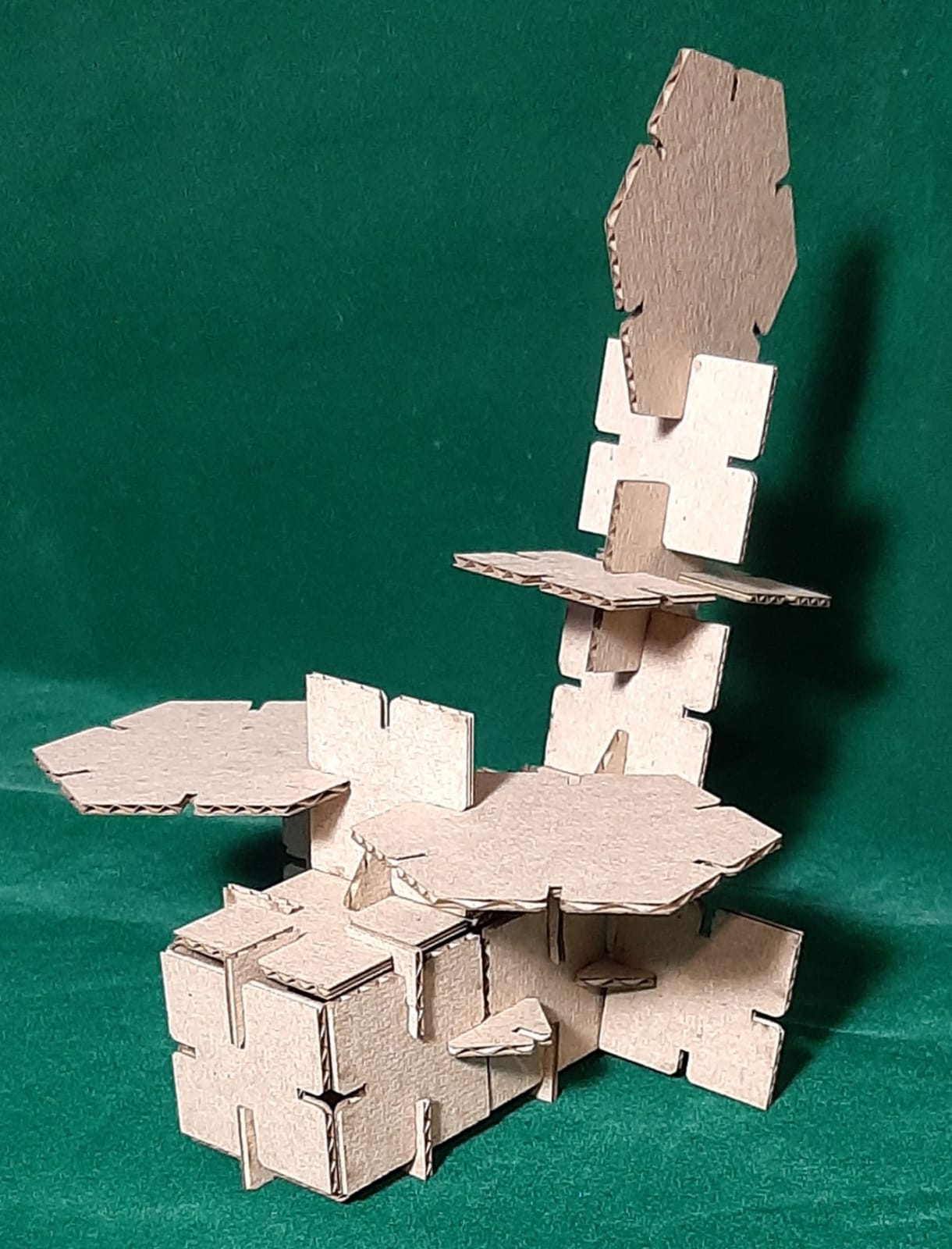
Finally, I assembled my 3D objects. (Extra credit include elements that aren’t flat)
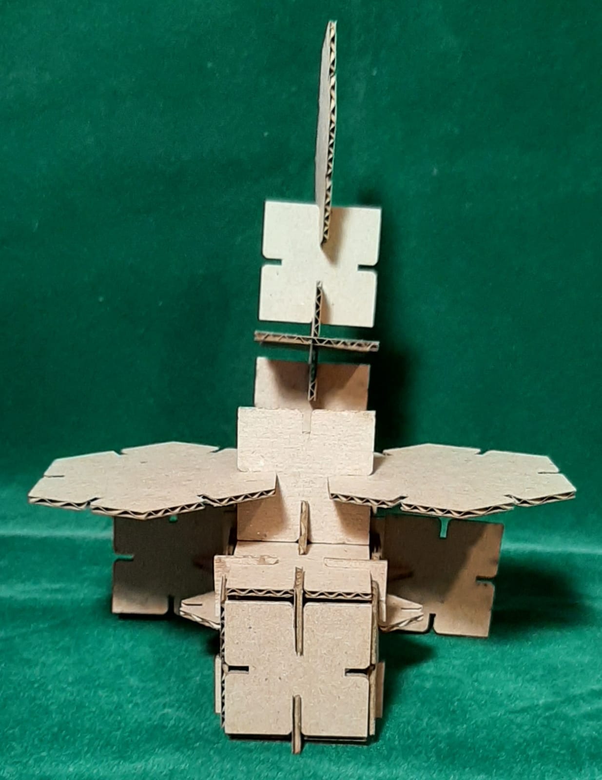
Helicopter front view.
Helicopter profile view
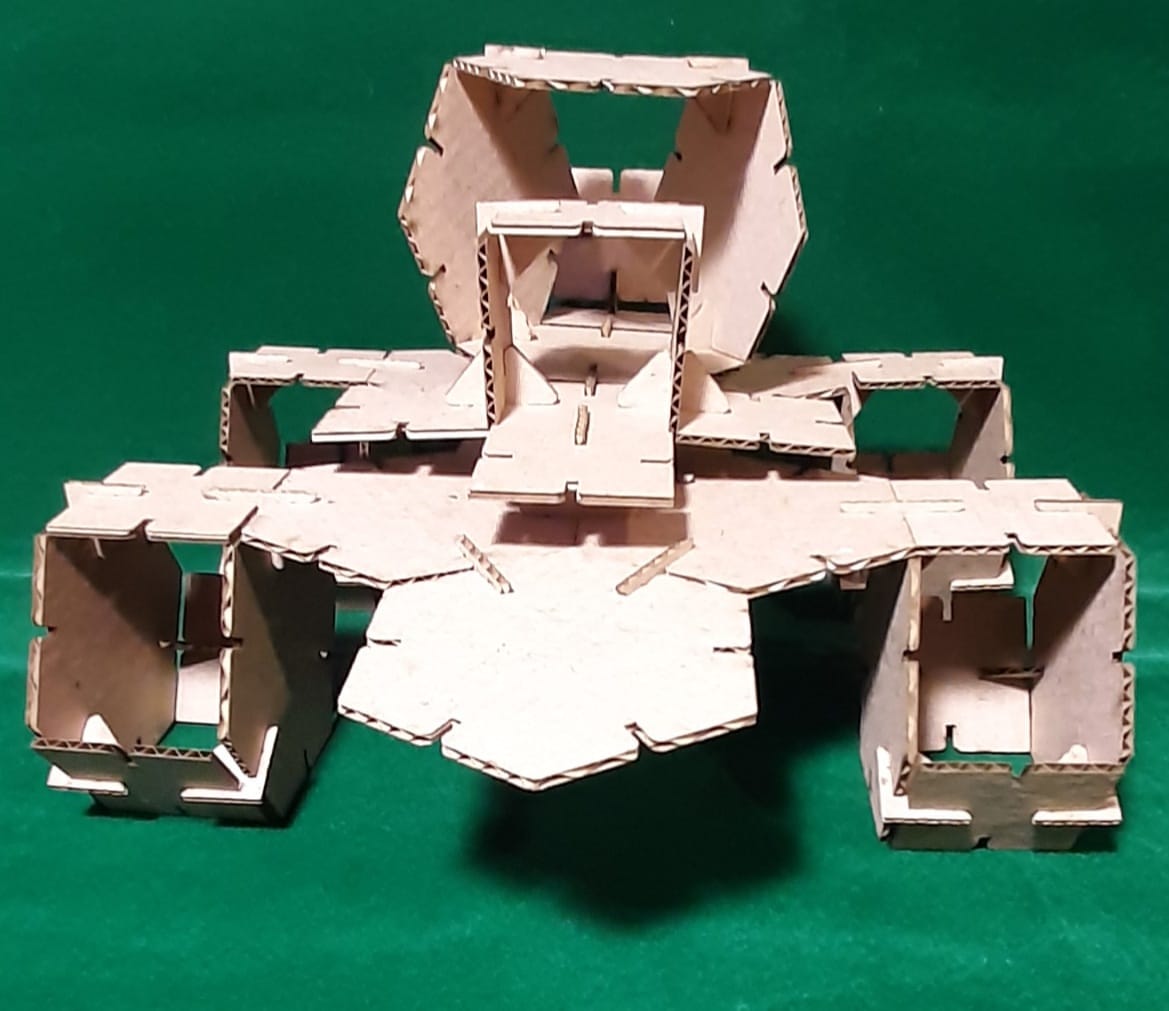
Big foot front view.
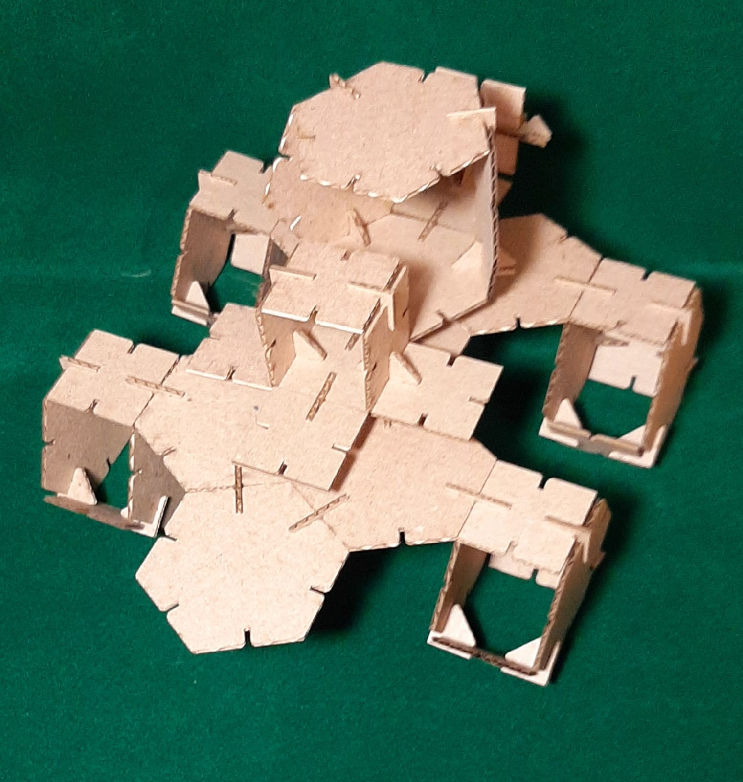
Big foot profile view.
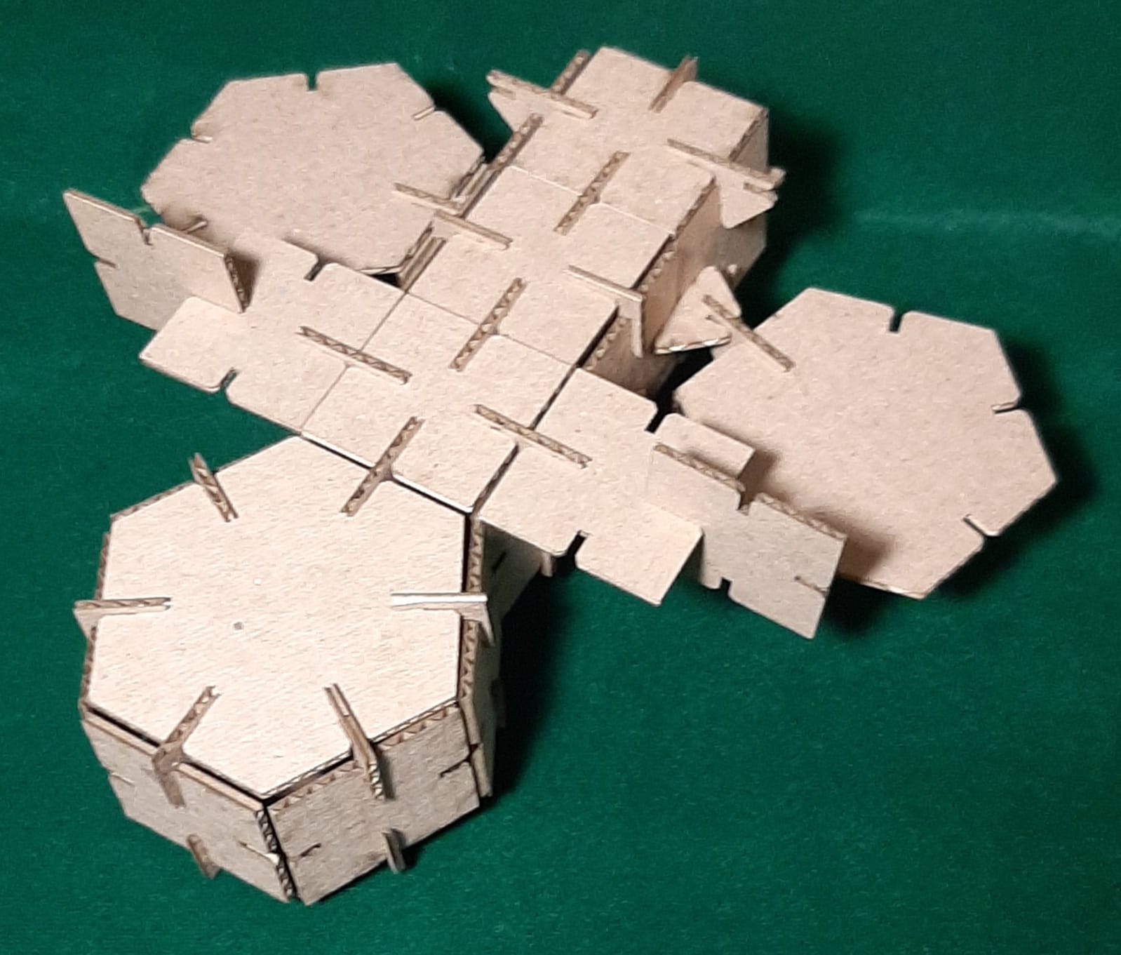
Ship top view.
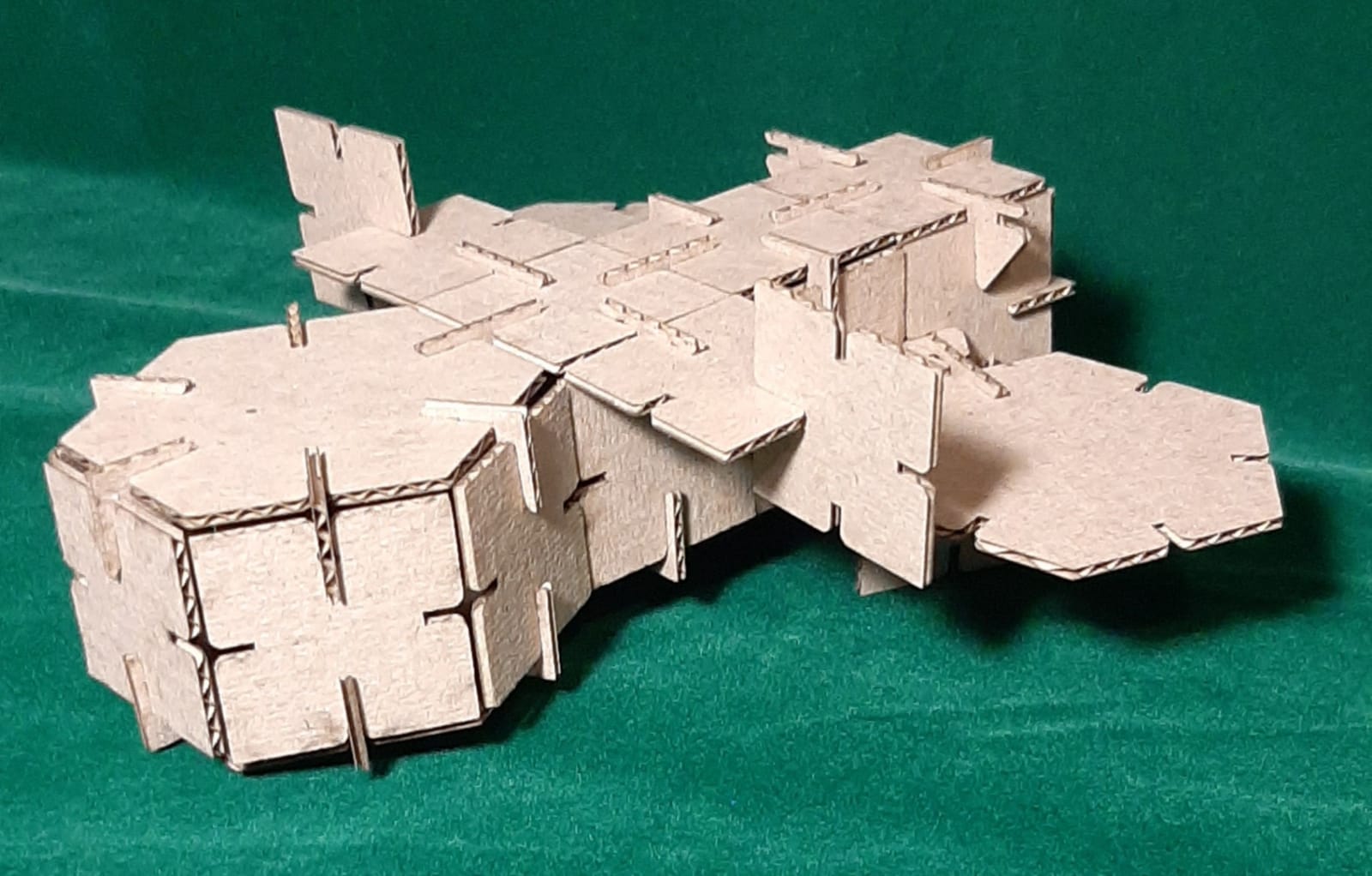
Ship profile view.
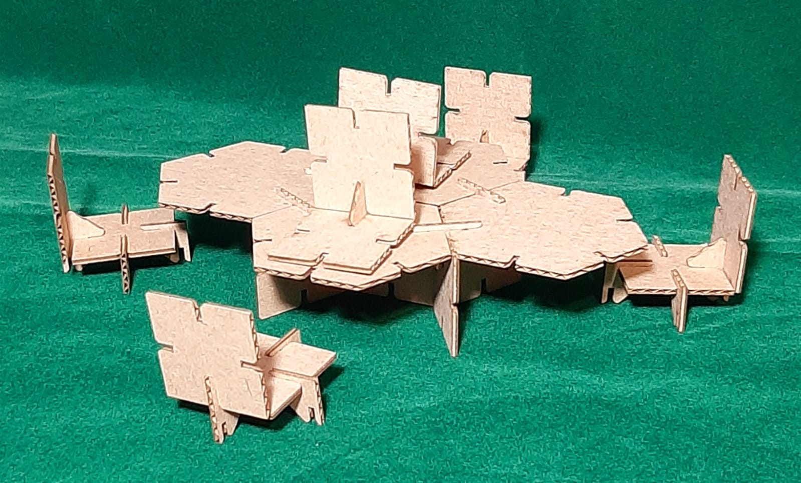
Table with chair profile view.
Table with chairs top view.