5. 3D Scanning and Printing
This week I learned about 3D scanning and printing.
5.0 Assignment of this week
5.0.1 Group assignment
Test the design rules for your 3D printers.
5.0.2 Individual assignment
Design and 3D print an object (small, few cm3, limited by printer time) that could not be made subtractively.
3D scan an object(and optionally print it).
5.1 Test the design rules for my 3D printers (FDM/FFF)(as group assignment)
5.1.1 Design rules for my 3D FDM/FFF method printer
FDM(Fused Deposition Modeling)/FFF(Fused Filament Fabrication) method 3D printers are very popular in maker community.
These printers are available in various sizes, grades, styles and prices.
There are four 3D printers in our Lab. All of them use FDM/FFF method.
I also have my own FDM/FFF 3D printer in my home. It is ‘Anycubic Kossel Plus’ with delta-configuration(it has a circle-shaped build plate and 3 step motors for positioning of a print head).
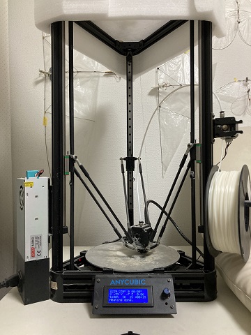
Technical data of Kossel Plus
| Build size | 230 (diameter) x 300 (height) mm |
| Printing technoogy | FDM(Fused Deposition Modeling) |
| Extruder | Single |
| Layer solution | 0.1 - 0.4 mm |
| Travel Speed | 60 mm/s |
| Print Speed | 20 - 60 mm/s |
| Nozzle | 4 mm diameter |
| Supported print materials | PLA, ABS, HIPS, wood |
| Retail price | around 199 US$ |
I checked the design rules of the printer as follows:
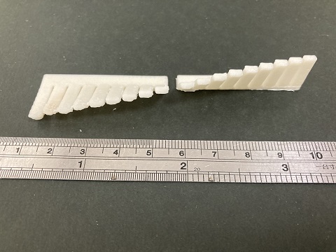
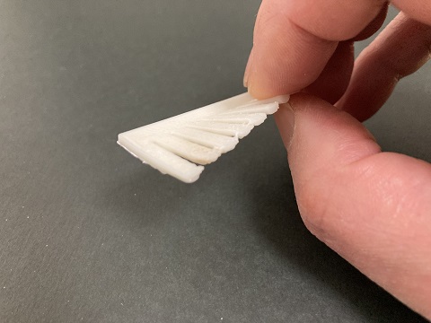
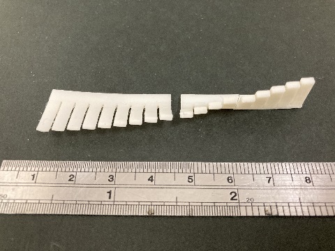
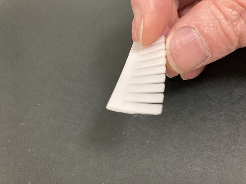
5.1.1.1 Design rule for over-hanged shapes
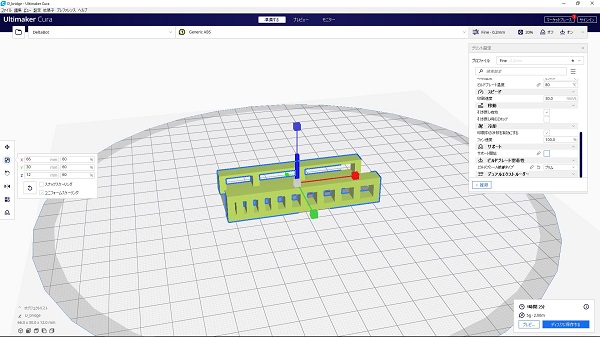
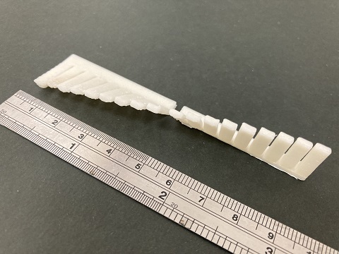
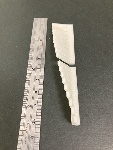
I used the test data with various angled flat plates. I printed it without supports. I used ABS filament and Cura as a slicing software.
Even without supports, most of plates could be printed, only 80 degrees one(almost horizontal) dropped down.
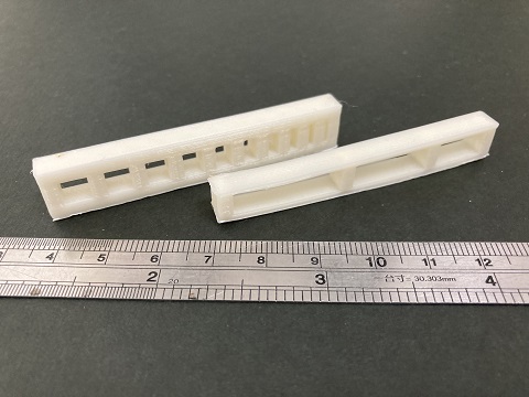
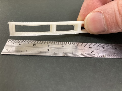
5.1.1.2 Design rule for bridged shapes
I printed the test data with several bridged shapes without supports.
Even without supports, most of bridges could be printed, only 25 mm long one slightly dropped down.
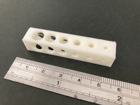
5.1.1.3 Design rule for holes
I printed the test data with several holes in various diameters. Some of the holes were vertical and the others were horizontal.
All holes could be printed well, but printed diameters were slightly smaller than designed(arround 0.5 mm)
Overall results were quite satisfing for me. ‘Kossel Plus’ is a good printer!
Data files:
angle.step
bridge.step
holes.step
Design and 3D print an object (small, few cm3, limited by printer time) that could not be made subtractively
5.2 Design and 3D print an object that could not be made subtractively (FDM/FFF)
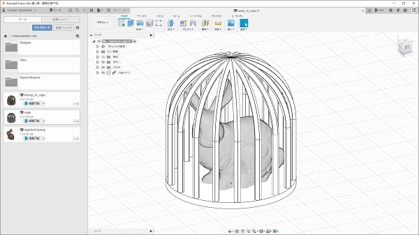
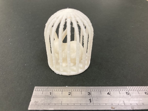
I designed ‘a rabbit in a cage’. A small statue of rabbit(famous ‘Stanford bunny’) sits in a wire cage.
It should be assembled from mutiple parts with conventional molding/engraving methods, but it can be 3D printed as a single mold.
I imported .obj(mesh) file of the rabbit to Fusion 360 and scaled up by ten times. I inserted the rabbit to a wire cage(solid) which I had separately designed. Then I exported them as a single STL file for printing.
I found that mesh data and solid data couldn’t be saved as one file. So I saved them separately.
Data files:
cage.step
Extra:
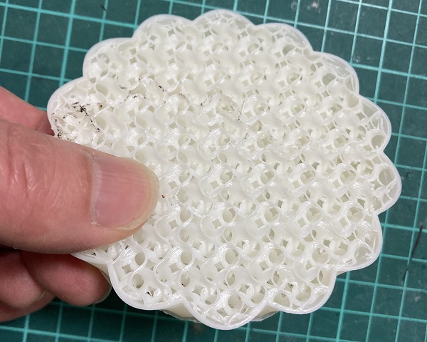
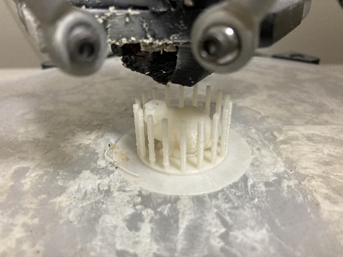
This is a failed print which unexpectedly shows its inner structure. Slicer software generates such structure automatically when infill setting is <100%.
This feature contributes to reduce filament comsumption and weight of the printed object. Also these structure is difficult to be made subtractively…
5.3 Test the design rules for my 3D printers (MSLA)
5.3.1 Design rules for my MSLA method 3D printer
MSLA(Masked Stereolithography Apparatus) printing is a modified form of SLA(Stereolithography Apparatus) printing.
MSLA printing works on almost the same concept as SLA. Liquid resin is cured by exposure to ultraviolet light, instead of using a controlled laser beam to trace each layer
MSLA printers use a larger UV light source and then mask it with an LCD screen(in less expensive models, it may be diversion parts from smart phones)
Print resolution of MSLA method is defined by pixel size of LCD screen, so by far higher than FDM/FFF method whose resolution is limited by nozzle diameter.
I have my own MSLA printer named ‘ELEGOO Mars’, which may be one of low-end models as a MSLA printer.
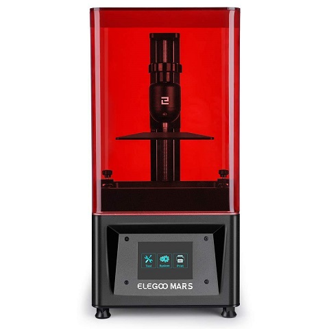
Technical data of ELEGOO Mars
| Build size | 120 (X) x 68 (Y) 155 (Z) mm |
| Printing technoogy | LED Display Photocuring |
| Light Source | UV Integrated Light(wavelength 405nm) |
| XY Resolution | 0.047mm |
| Layer solution | 0.01 - 0.2 mm |
| Print speed(Vertical) | 22.5 mm/h |
| Retail price | around 150 US$(discounted) |
I checked the design rules of the printer as follows:
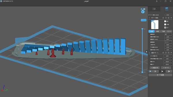
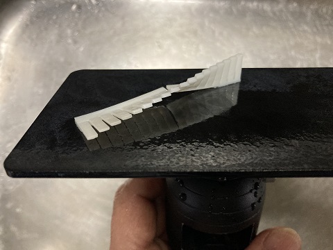
5.3.2 Design rule for over-hanged shapes
I used the test data with various angled flat plates. I printed it without supports. I used water washable photo polymer and ChiTu DLP Slicer.
Even without supports, all plates could be printed well.
5.4 Design and 3D print an object that could not be made subtractively (MSLA)
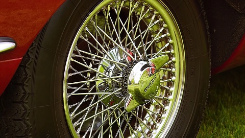
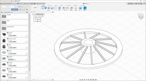
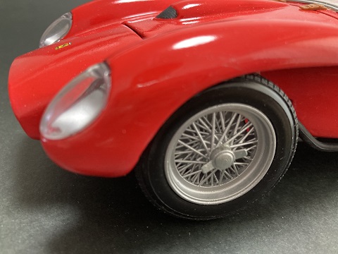
Very high resolution ability of MSLA printing encouraged me to develop more complicated objects: ‘wire spoke wheel’.
Wire spoke wheel used to automobile, motorcycle or bicycle is one of my favorite industrial design. Real thing is composed of several parts like hub, rim, wire spokes and nipples, etc.
It is rather difficult to reproduce fineness and intricateness of wire spoke wheel in miniature model car size by plastic with injection moulding method.
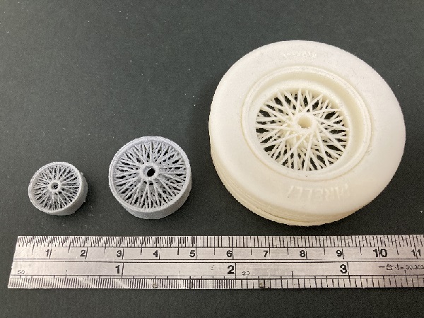
By utilizing MSLA printing, we can easily make faithful miniature wire spoke wheels in a single mould. It helps us greatly in scale model making.
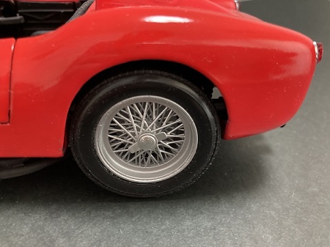
Real thing:
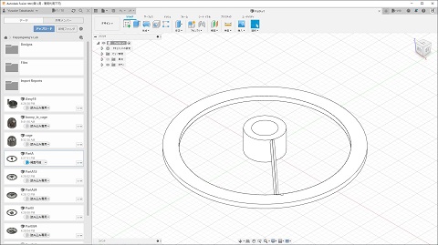
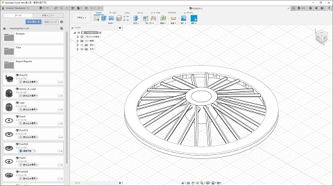
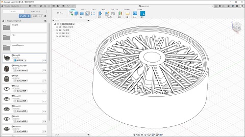
Design process:
Design a single spoke at first. Then repeat duplication(rotation, mirror) for required number of times.
3D printed parts(scale:1/32-1/18-1/12):

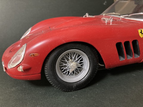
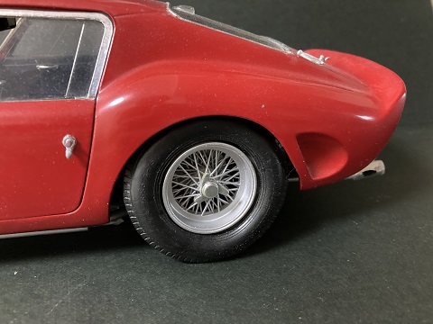
Mounted to the model(scale:1/18):
Mounted to the model(scale:1/12):
Data files:
spokewheel.step
5.5 3D scan an object
5.5.1 DIY 3D scan system (AAScan)
As there was not any 3D scan tools at present in our lab, I decided to make my own 3D scan system by myself. The design came from an open source project called AA-Scan by QLRO.
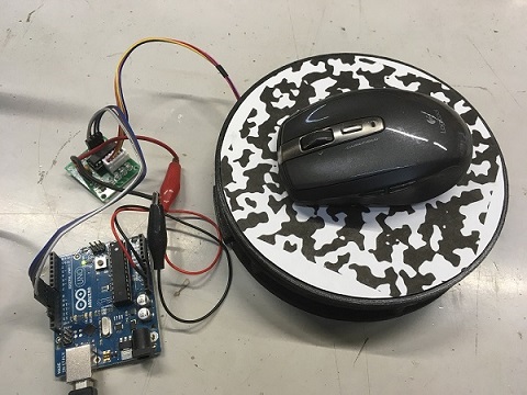
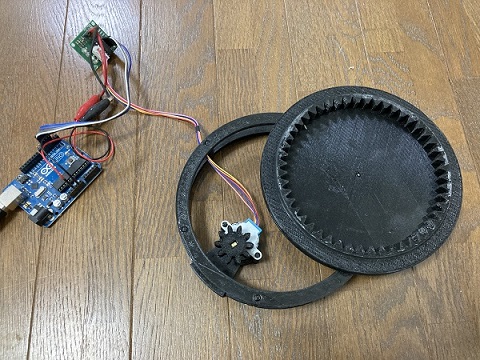
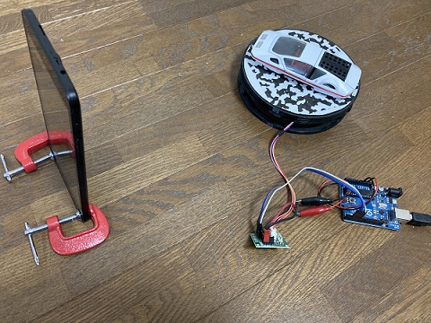
The system is consists of a smart phone camera/tablet and a 3D printed, small step motor-powered turn table controlled by Arduino. The system generates source image files for photogrametric processing.
Detailed information about how to make, set up and use the device is available at the project page.
Its scanning ability was relatively low (may be from the limitation of my Android tablet I used) compared with industrial grade laser scanners, but was worth for my effort.
All the information and source files are available from the following web sites. Thank you QLRO!
Thingiverse: AAScan: Open source, minimalist, fully automated 3D scanner based on Arduino and Android!
GitHub: QLRO/AA-Scan
5.5.2 Cloud GPU (Google Colab)
Meshroom by AliceVision is a great open source software. But sometimes it takes long time for processing the data, or simply impossible on old PCs without high power GPU.
So I tried ‘Cloud GPU’. The idea came from the article by kotauchisunsun(Psychic VR Lab) on Qiita.
This method uses Google Colab(Jupyter Notebook on cloud) as a virtual graphic engine. Meshroom runs on the instance of the cloud service. Scanned images were uploaded to there and processed to a mesh file with color texture.
When the proccess is completed, we receive a notice mail from the service and we can download the processed files. It worked quite well and helpful for me, because my PC didn’t have NVIDIA GPU!
Links:
Welcome To Colaboratory
I want to do photogrammetry with another person’s GPU!
5.5.3 Scanned images (post-processed)
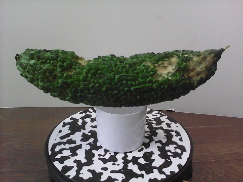
I scanned several objects using the system, the results were so-so… But color textures were excellent, maybe an advantage of photogrametric method.
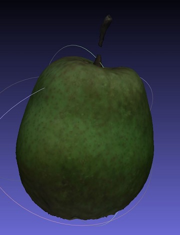
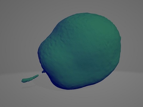
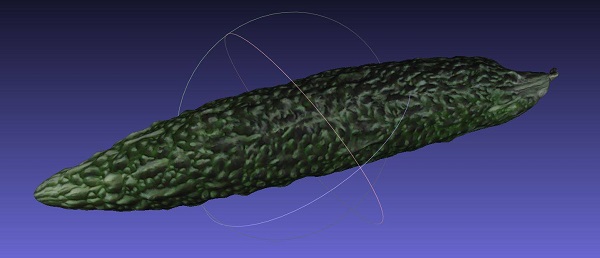
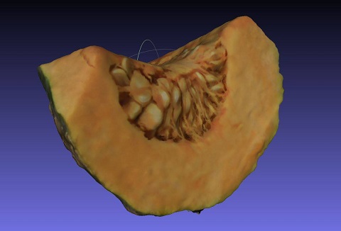
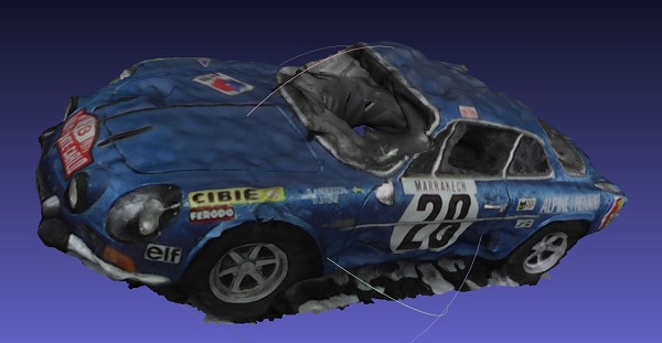
These screenshots are from MeshLab which I used to post-process the mesh files.
Data files:
mesh.zip