12. Input Devices
This week I learned about Input Devices.
12.0 Assignment of this week
12.0.1 Individual assignment
Measure something:
add a sensor to a microcontroller board that you have designed and read it
12.0.2 Group assignment
Probe an input device’s analog levels and digital signals
12.1 The personal object of the assignment this week
As I am planning in my final project to integrate aerodynamic auto-leveling and self-balancing functions, so I focused accelerometer/gyroscope devices.
These devices have been widely used for the purpose and several professional/hobby grade products are available. I would like to make my own.
12.2 Design
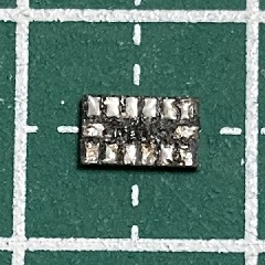
I checked the parts inventry of our lab and I found a few ‘ADXL343’ accelerometer chips.
The chips were so small(3 mm x 5 mm x 1 mm LGA package) that I was not confident of making them work on boards designed by myself.
So I decided to use a sample design(hello.ADXL343) for lower lisks.
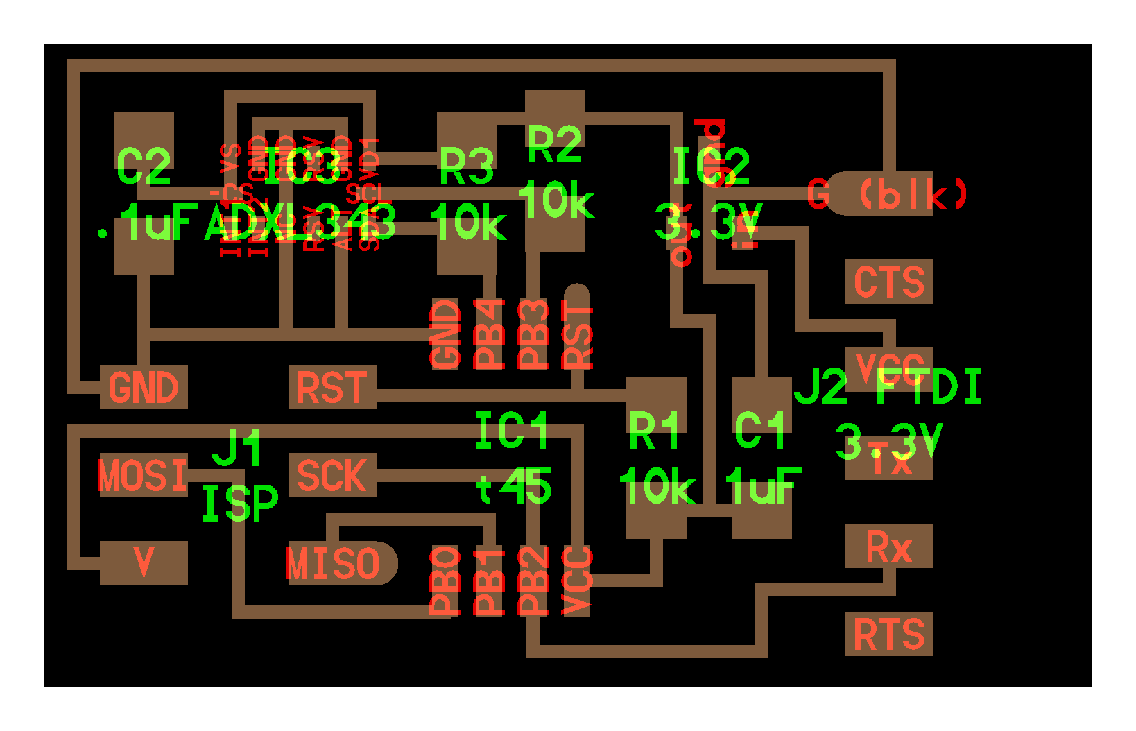
Board design:
hello.ADXL343.svg:

STL file:
hello.ADXL343.stl
G-code file:
hello.ADXL343.cnc
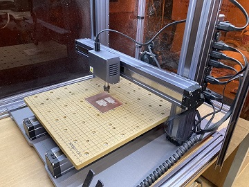
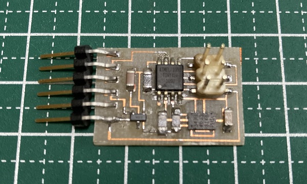
I used ‘Snapmaker 2.0’ again to engrave the board.
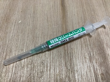
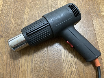
12.3 Soldering
I used a heat gun and a solder paste this time. They worked well for most of the chips, except of ADXL343.
ADXL343 has flat pads on the bottom of the package instead of pins and pad pitch is only 0.8 mm. My first try was failed (circuit shorted out under the chip).
I removed the chip using a heat gun, tinned the traces on the board and the pads on the chip. Next I put the chip on the board carefully, added heat thoroughly.
Finally I got the board working!
12.4 Programming the board
I used a sample C code(hello.ADXL343.c) and makefile.
I ran the make command and wrote the firmware into the board.
12.5 User interface program
I used a sample python code(hello.ADXL343.py) as a user interface. I should commented out some lines to make the program work on my WIndows PC.
The lines commented out by ‘#’:
if (len(sys.argv) != 2):
   print(“command line: hello.accel.45.py serial_port”)
   sys.exit()
port = sys.argv[1]
open serial port
ser = serial.Serial(port,9600)
I fixed the port number according to the USB-serial converter I used:
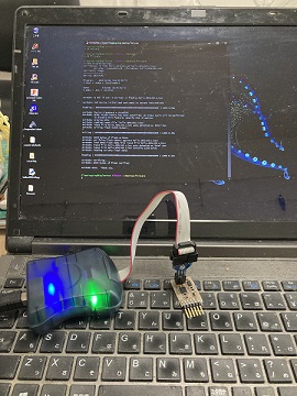
ser = serial.Serial(“COM9”,9600)12.6 Test
I connected the board to a USB-Serial converter and then connected them to my PC.
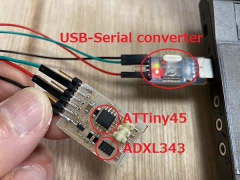
Test program worked well:
12.7 Test by another board
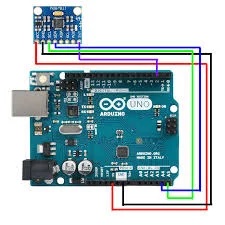
I found a small break-out board named GY-521 from my parts stock. There was a 6 axis accelerometer/gyroscope chip named MPU-6050 on it.
I made a test circuit with Arduino UNO and a bread board refer to the following articles:
How to use GY-521 (3-axis accelerometer / gyro module) with Arduino
GY-521 MPU6050 3-Axis Acceleration Gyroscope 6DOF Module Tutorial
Wiring diagram:
Test:
It also worked well.
MPU-6050 communicates with MCU by I2C. It seems to be very similar with LSM6DS33, so we would be able to convert the sample LSM6DS33 code for MPU-6050(I haven’t tried yet).
12.8 Probe an input device’s analog levels and digital signals(as group assignment)
I checked analog output levels of the micro:bit on-board accelerometer(LSM303AGR) via PC’s serial port and serial monitor.
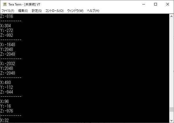
Result:
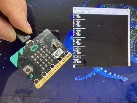
Cap.1(moving):
Cap.2(Static):
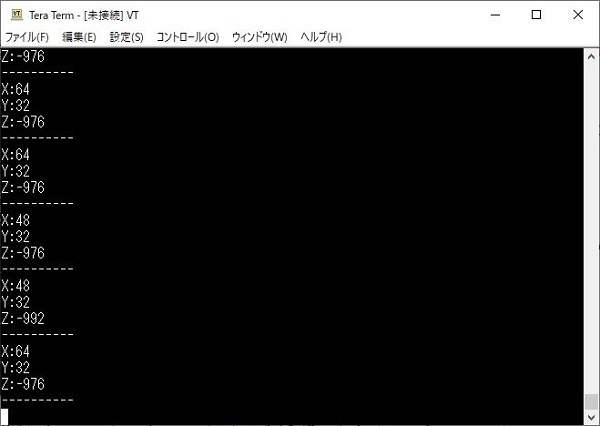
Analog levels(lower/upper limit): -2048 to 2048 (milli-g) for x/y/z axis
Digital signals: N/A
It seems that gravitational acceleration are detected in z axis(See Cap.2).
Javascript program for micro:bit:
basic.forever(() => {
    serial.writeValue(“X”, input.acceleration(Dimension.X))
    serial.writeValue(“Y”, input.acceleration(Dimension.Y))
    serial.writeValue(“Z”, input.acceleration(Dimension.Z))
    serial.writeLine(“----------“)
    basic.pause(500)
})
12.9 Conclusion
I could test some accelerometer/gyroscope chips and learn how to use them this week. But in order to integrate them to my final project, I should master PID control method using these chips.
Some internet articles about a reverse pendulum using these chips seem to be very useful to learn PID control. I would test them soon.