Final Project
Summary
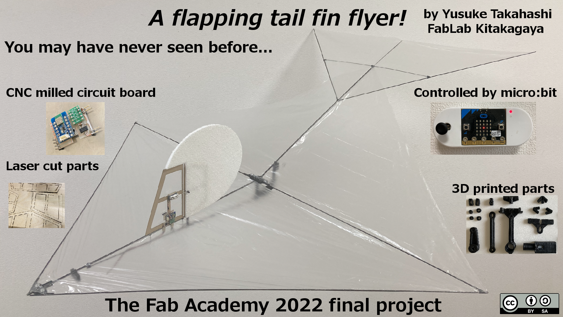
Poster
Video
Exploring new format of flapping flight mechanism
Background
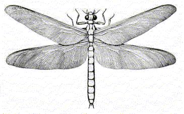
On our planet, flying animals have a long history of evolution. Fossil records indicate that they have already lived on the earth in three hundred million years ago.
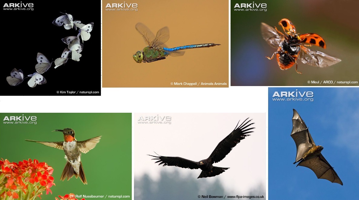
There are very wide variation in flying animals as to size, wing struture, flapping mechanism. But they all share a common basic format: Symmetry flapping wings.
Why do they share a single common format? Request of laws of physics? None of us know the reason exactly.
Motivation
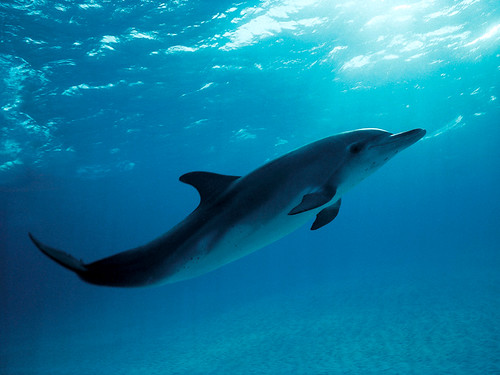
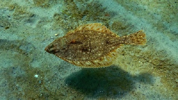
When we turn our eyes into sea, we see several animals use wider variation of mechanism to move in water.
One of the most popular way is “tail fin”. Many fishes, whales, dolphins, etc. have large fins on their tail.
They swing their fins to swim in water efficiently. My question: does the same approach also work in the air? In other words, could it be possible to fly by flapping tail fin?
Intension of the project
What I would make
AS to tail fin swinging motion of water animals, there are two major styles: vertical swing and horizontal swing. Vertical swing is also called ‘dolphin kick’. I focused on ‘dolphin kick’ style for the project.
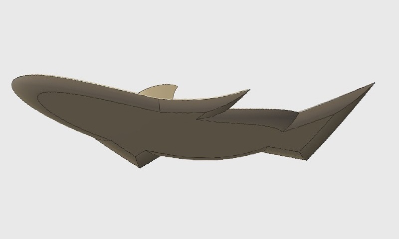
Final model image
I imaged that the final model would be fairly large, around 1 meters wing span.
It would resemble a dolphin, a flat fish or a halibut, but it is a not swimmer, but a flapping-winged flyer!
Project development
Design Key
I planned to build multiple airframes vary in dimension, to compare flight performance depending by their size.
But they would share some common design keys:
- Composed of carbon rods with 3D printed parts like joint, motor mount, crank and link, etc.
- Simple crank-and-link flapping mechanism
- Remote controlled by micro:bit
Construction
3D print parts
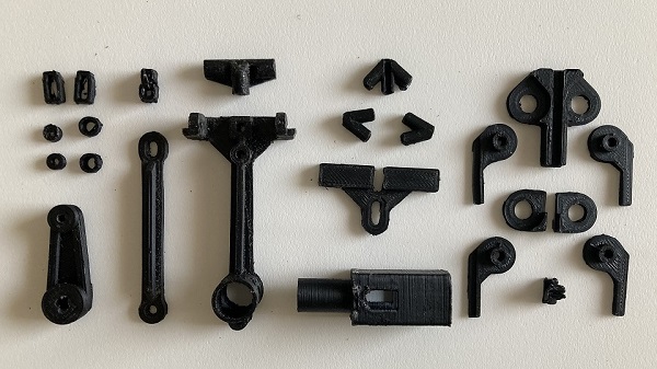
Mechanical components and various small parts were designed by 3D CAD and printed using a FFF type 3D printer. I chose ABS material, which was known for durability.
Carbon rod structure
Carbon rod is a kind of CFRP(Carbon Fiber Reinforced Plastic). CFRP is very light and strong material widely used for sports gear, airplane and recing cars.
Carbon rod is available in various size(diameter and length) from internet shop.
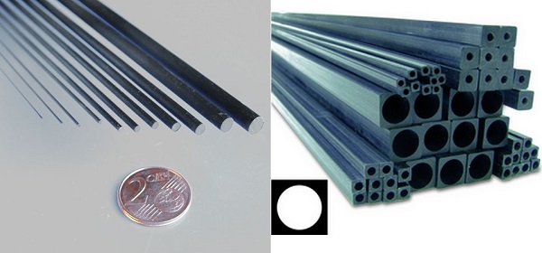
I used various size of fine carbon rods for main frame. Carbon rods is very hard material and should be cut using diamond files.
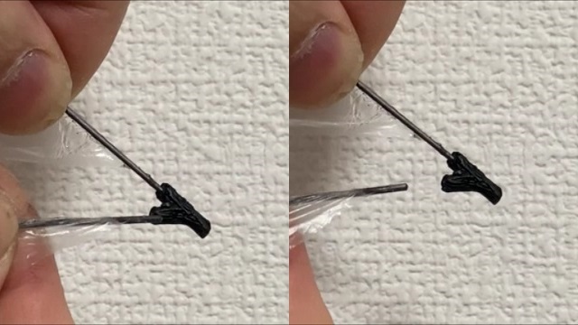
Carbon rods were push-fitted with 3D printed ABS joint parts.
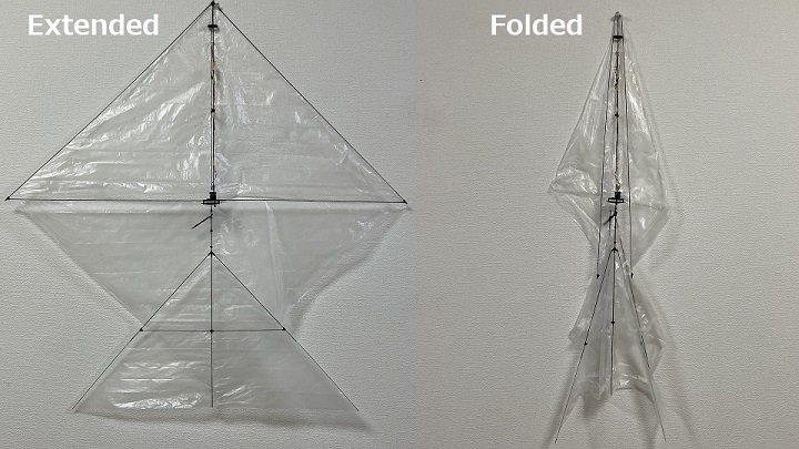
Push fitted sections are easy to pull off, so the airframes can be folded compactly to ease strage and transportation.
Laser cut
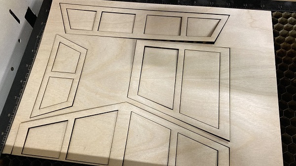
A vertical fin, rudder, etc. were designed by 2D CAD and laser cut from thin Finnish birch veneer board.
CNC mill
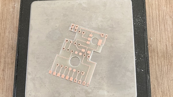
The circuit board for the control unit was designed by PCB CAD and CNC milled. The back of the board was thinned down by sanding for weight reduction.
Remote controller

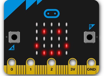
micro:bit has a 3-axis accerometer and a couple of push buttons on board, so it can be used as a motion-sensing controller.
But I wanted to add a traditional analog joystick for throttle control, so I designed a plastic case using 3D CAD and 3D-printed the parts. I used PETG material for the case.
Control unit
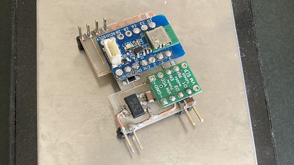
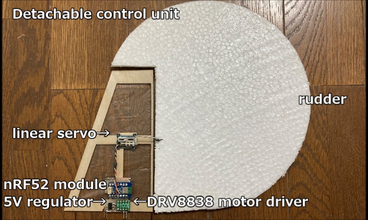
The control unit integrates a radio receiver(nRF52 module), a motor driver, a regulator and a servo motor for steering on one board.
The unit is detachable, so it can be used for multiple airframes sharing the common connecter design.
Programming
micro:bit is 1/2 credit card size single board computor developped by BBC for educational purpose. It comes with several I/O pins, LED array, push buttons, motion sensors, etc.
It can be programmed with several languages like C++, MicroPython, MakeCode(internally JavaScript) and Scratch.
It uses Nordic nRF5x series chip as MCU, so it can control other micro:bits and even non-micro:bit nRF5x modules as remote peripherals.
micro:bit is a bit bulky as a receiver for light weight flying objects, so I decided to use a compact nRF52 module for a receiver.
![]()
Input device
I programmed micro:bit as an input device(remote controller/radio transmitter).
My javaScript code for remote controller:
input.onButtonPressed(Button.A, function () {
    Status = “ON”
})
input.onButtonPressed(Button.B, function () {
    Status = “OFF”
    basic.clearScreen()
    radio.sendValue(“THR”, 0)
    radio.sendValue(“RUD”, 0)
})
let Rud = 0
let Thr = 0
let Status = “”
radio.setGroup(144)
Status = “OFF”
basic.forever(function () {
    if (Status == “ON”) {
        Thr = pins.map(
        pins.analogReadPin(AnalogPin.P0),
        32,
        992,
        0,
        1024
        )
        Rud = pins.map(
        input.rotation(Rotation.Roll),
        -90,
        90,
        -90,
        90
        )
    }
    basic.clearScreen()
    led.plot(pins.map(
    Rud,
    -90,
    90,
    0,
    4
    ), pins.map(
    1024 - pins.analogReadPin(AnalogPin.P0),
    32,
    992,
    0,
    4
    ))
    radio.sendValue(“THR”, Thr)
    radio.sendValue(“RUD”, 90 - Rud)
})
Output device
I programmed MDBT42V(nRF52) module as a MCU of output device(remote peripheral/radio receiver).
My javaScript code for receiver:
radio.onReceivedValue(function (name, value) {
    if (name == “THR”) {
        pins.digitalWritePin(DigitalPin.P0, 1)
        pins.analogWritePin(AnalogPin.P1, value)
    } else if (name == “RUD”) {
        servos.P2.setAngle(value)
    } else if (name == “ELE”) {
        pins.digitalWritePin(DigitalPin.P12, 0)
    } else {
        pins.digitalWritePin(DigitalPin.P0, 0)
        pins.digitalWritePin(DigitalPin.P1, 0)
        pins.digitalWritePin(DigitalPin.P2, 0)
        pins.digitalWritePin(DigitalPin.P12, 0)
    }
})
radio.setGroup(144)
You may feel that necessary information like library inclusion, etc. are missing in these codes.
As to micro:bit programming using MakeCode Editor which was exclusively developped for micro:bit, the editor automatically add these information when compiling the codes.
Caution: In order to make the compiled hex files work with non-micro:bit nRF5x chips, the hex files should be slightly modified(See my Week13 Assignment page for detailed information).
Prototypes
At first, I built a series of small airframes as prototypes prior to full scale deelopment.
PoC(Proof of Concept) model
I checked the potential of my idea using small scale rubber-powered model named “Micro” and found that “flapping tail fin flyers” were actually possible.
Flapping mechanism of “Micro”:
Specifications of “Micro”:
| Wing span | 480 mm |
| Length | 580 mm |
| AUW(all-up weight) | 10 gram |
| Wing loading | 0.007 gram / cm2 |
| Rubber | FAI TAN Super Sport 2.4 * 1000 mm |
Larger, motorized model
Once I could find that the idea is promising enough, I stepped further.
I designed a larger, motorized model of the first prototype. It was wireless controlled by micro:bit.
Flapping mechanism of “Mini”:
Specifications of “Mini”:
| Wing span | 600 mm |
| Length | 660 mm |
| AUW | 18 gram(/w battery) |
| Wing loading | 0.008 gram / cm2 |
| Motor size | 6 * 15 mm |
| Gear unit | plastic planetary gear |
| Gear reduction ratio | 1 : 171 |
| Battery | Li-po 1 cell 3.7V 100 mAh |
Final projects
Based on the experience obtained by prototype development, I made a couple of airframes as my final project. One was named “Lite”, designed for indoor flight and another was named “Heavy”, designed for outdoor flight.
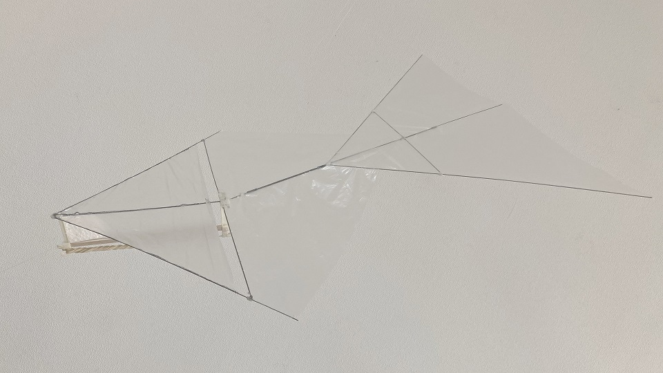
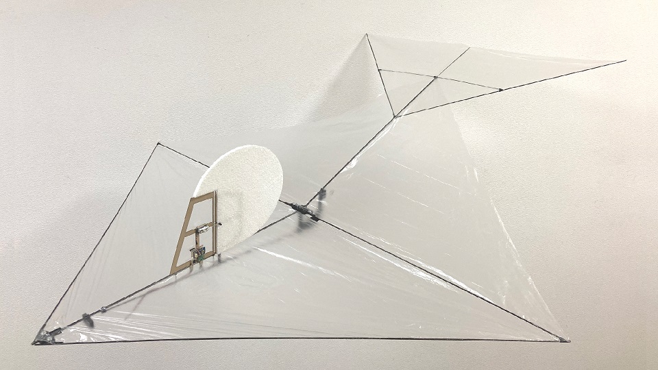
Indoor model
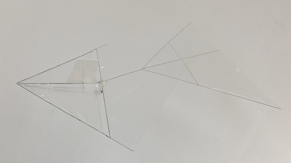
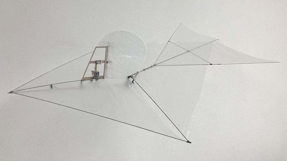
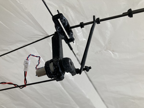
I designed “Lite” mainly for indoor flight.
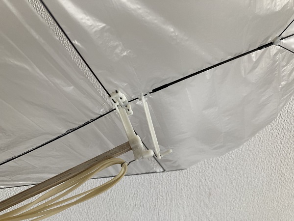
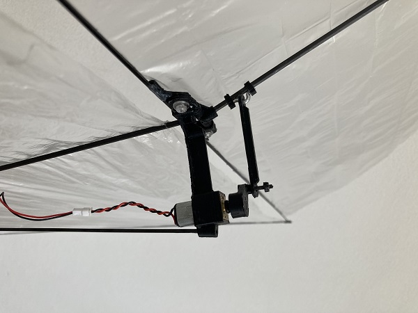
Flapping mechanism of “Lite”:
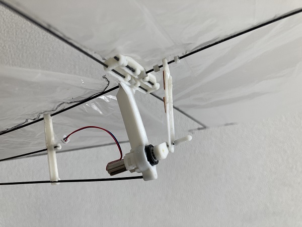
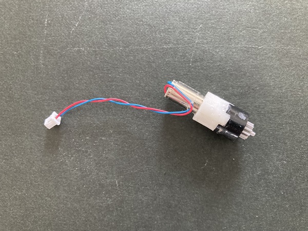
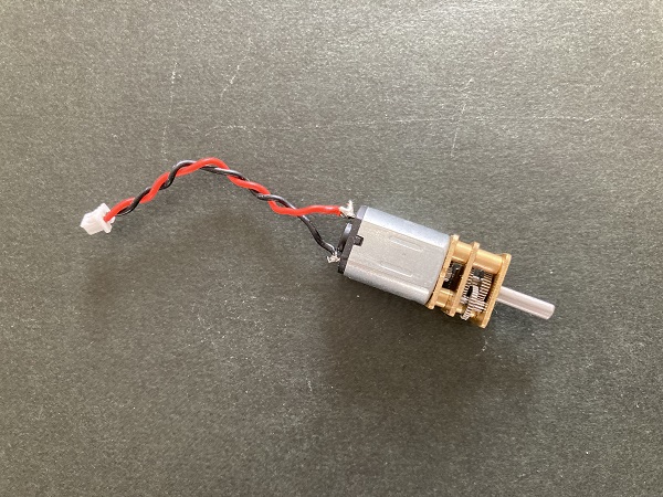
Motor & gear reduction unit of “Lite”(also used for “Mini” unit weight: 2.8 gram):
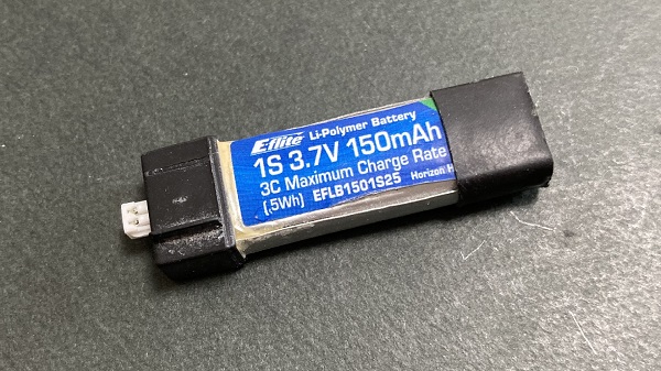
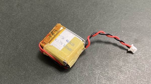
Li-po 1 cell 3.7V 150 mAh battery for “Lite”(also used for “Mini”. unit weight: 4.3 gram):
Specifications of “Lite”:
| Wing span | 800 mm |
| Length | 800 mm |
| AUW | 35 gram(/w battery) |
| Wing loading | 0.01 gram / cm2 |
| Motor size | 6 * 15 mm |
| Gear unit | plastic planetary gear |
| Gear reduction ratio | 1 : 171 |
| Battery | Li-po 1 cell 3.7V 150 mAh |
Outdoor model
I also built “Heavy” mainly for outdoor flight. This was the one of the heaviest ornithopters I had ever designed.
Outdoor test flight of “Heavy”:
Flapping mechanism of “Heavy”:
Motor & gear reduction unit of “Heavy”(unit weight: 9.6 gram):
Li-po 3 cell 11.1 V 120 mAh battery for “Heavy”(stacked of 3 single cells. unit weight: 9.1 gram):
Specifications of “Heavy”:
| Wing span | 1000 mm |
| Length | 1200 mm |
| AUW | 60 gram(/w battery) |
| Wing loading | 0.013 gram / cm2 |
| Motor size | 10 * 12 * 15 mm |
| Gear unit | longitudinal mounted metal gear |
| Gear reduction ratio | 1 : 50 |
| Battery | Li-po 3 cell 11.1V 120 mAh |
Parts list
- Parts list for the airframe of “Lite”:
| Parts name | Description | Cost(US$) | Data |
| Carbon rods | 1.2 mm dia. * 1000 mm rod * 3 1 mm dia. * 1000 mm rod * 1 1.6 mm sq. * 500 mm pipe * 1 |
16$ | |
| 3D print parts | 1 set |
PartsSet1.step PartsSet2.step PartsSet1.stl PartsSet2.stl |
|
| Gear reduction unit | Precision Micro 10mm Planetary Gear Motor * 1 (only gear unit used. motor should be replaced) |
1$ | |
| Replacement motor | 615 Brushed Coreless Motor * 1 (for replacement) |
1$ | |
| Thin plastic film for wing surface | 0.01t * 500 mm * 2000 mm |
0.5$ | |
| Cable, connectors, etc. | 2$ | ||
| Battery | 3.7V 130mAh Lipo Battery * 1 |
3.5$ | |
| Total | 24$ |
Parts size and cost would vary by the models.
- Parts list for the remote controller:
| Parts name | Description | Cost(US$) | Data |
| Computer board | micro:bit v2.2 * 1 | 20$ | |
| 3D print parts | 1 set |
1$ | ControllerCase.step
ControllerCase.stl |
| Circuit board | I used a sample circuit board supplied from Switch Science It is to be replaced to original board |
||
| Joystick | Analog joystick * 1 |
4.5$ | |
| Total | 25.5$ |
The controller can be used for all the motorized models.
- Parts list for the control unit:
| Parts name | Description | Cost(US$) | Data |
| nRF52 module | MDBT42V breakout board * 1 Pin pitch of MDBT42V was too narrow for hand-soldering, so I used a sample breakout board supplied from Switch Science (not catalog listed) |
10$ | |
| Motor driver IC | DRV8838 breakout board * 1 Pin pitch of DRV8838 was too narrow for hand-soldering, so I used the breakout board |
8$ | |
| 5V regulator | LM2940IMP5 * 1 | 3$ | |
| Servo motor | GS-1502 1.5g/ 80g-cm/ 0.12sec Linear Servo * 1 | 6$ | |
| Original circuit board | 1 | CircuitBoard.step CircuitBoard.svg |
|
| Laser cut parts | 1 set |
1$ | ControlSurfaces.svg |
| Total | 28$ |
The control unit is shared by all the motorized models.
- Programs:
| Parts name | Description | Data |
| Transmitter | JavaScript code for micro:bit | microbit-Controller.js |
| Transmitter(hex) | Hex file for micro:bit | microbit-Controller.hex |
| Receiver | JavaScript code for MDBT42V(nRF52) | microbit-Receiver.js |
| Receiver(hex) | Hex file for MDBT42V(nRF52) | microbit-Receiver_Mod.hex |
Requests and answers
| Questions/requests | Answers |
| What do they do? | They make a powered flight using a flapping tail fin |
| Who's done what beforehand? | There have been several flapping wing flyers in nature or artificially, but flapping tail fin flyers were scarcey known. Although flapping tail fin swimmers are very popular in the water. |
| What did you design? | Digital desigend and manifuctured flapping tail fin flyers |
| What materials and components were used? | Fine carbon rods for frames, 3D printed plastic parts for mechanic components, thin plastic film for wing surface, a small electric motor /w gear reduction and linkages for driving a tail fin, a small linear servo motor, a single 3.7V litium polymer battery for a power source, and an integrated electric board for a control |
| Where did they come from? | It came from the bottom of the sea... |
| How much did they cost? | Around 80 US$ per 1 airframe /w controller & battery(Ready to Fly) |
| What parts and systems were made? | I designed an entire flapping mechanism for the airframe, 3D printed plastic parts for mechanic components and a remote controller casing, integrated electric board for a control, user interface program for input device(micro:bit), and control program for output device(motor and servo) |
| What processes were used? | 3D CAD, 3D print, PCB CAD, CNC mill, soldering, embedded programming, interface programming, and integrated assembly |
| What questions did need to be answered? | A powered flight using a flapping tail fin :is it possible on our planet? |
| How would it be evaluated? | It would become the first time proof of capability of flapping tail fin flyers |
Conclusion
I could show that flapping tail fin flyers were actuially possible. I’d like to enlarge the airframe to human scale next time!
Copyright and License
All the contents of the project are open source with Creative Commons license Attribution-ShareAlike 4.0 International (CC BY-SA 4.0).