15. Wildcard Week
This week I tried an extreme usage of FFF 3D printers as a wildcard week assignment.
15.0 Assignment of this week
Design and produce something with a digital fabrication process (incorporating computer-aided design and manufacturing) not covered in another assignment,
documenting the requirements that your assignment meets, and including everything necessary to reproduce it. Possibilities include (but are not limited to):
15.1 Hint
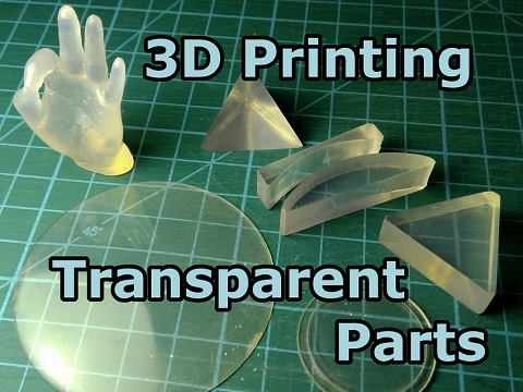
Although 3D printing was covered in week 05, but it is a versatile technology and has a very wide application. One of them (and haven’t been widely known yet) is printing transparent parts using FFF 3D printers.
Recently I read the article by Tomer Gluck(“3D Printing Transparent Parts Using FDM/FFF Printer”) in which the detailed information provided about the technique.
In the article, the author focused on light diffusion in the material which cause the parts translucent. He thought the most dominant cause of it was the inhomogeneity of the print. Under normal settings, the printer leaves small cavities (bubbles) inside the print. Each cavity acts as a small lens (as it is curved) and scatters the light passing through, obscuring any image standing behind the print and making it translucent. He expected that if he could eliminate these bubbles from the printing process, he could get optically clear prints, and he actually achived it.
I wanted to try it and check if the technique were to be applicable to other plastics.
(An image from the above article)
15.2 Basic idea
In order to eliminate bubbles which cause light diffusion in the material, we should print the parts consistent as much as possible by applying over-extrusion (flow rate or infill > 100 %).
Highest possible temperature and slow extrusion speed were also recommended in the above article, but I found through my own test that high tempeature didn’t result good at least in some plastics.
15.3 Design of a test piece
I designed a small test piece (simple cylinder shape was necessary to ease post process) by 3D CAD. Dimention of a piece is 25 mm diameter and 5 mm thickness.
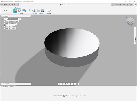
Data file:
TestPiece.step
STL file:
TestPiece.stl
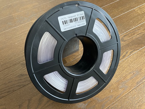
15.4 Test material
I chose PETG as my test material simply because I had a stock filament roll. PETG is widely used for food packaging and other purposes. It has a good transparency. It brought a different result about the best print setting compared with ABS selected in the referenced article.
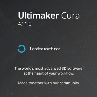
15.5 Slicing software
I used Cura as a slicing software. Cura is free and very popular in maker community. It is also used in the referenced article.
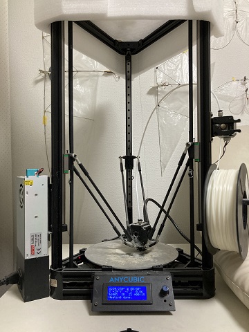
15.6 Printer
I used my own FFF 3D printer(Anycubic Kossel) as week 05 for the test .
15.7 Print
According to the referenced article, I tuned the print setting. The most important key was over-extrusion (flow rate or infill > 100 %). I set infill at 120 % (alarmed by the software, but it was possible).
In addition, I set print speed slower( 20 mm/s) than normal( 30 mm/s) and minimized layer height( 0.05 mm) than normal( 0.15 mm).
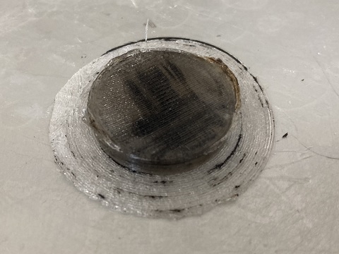
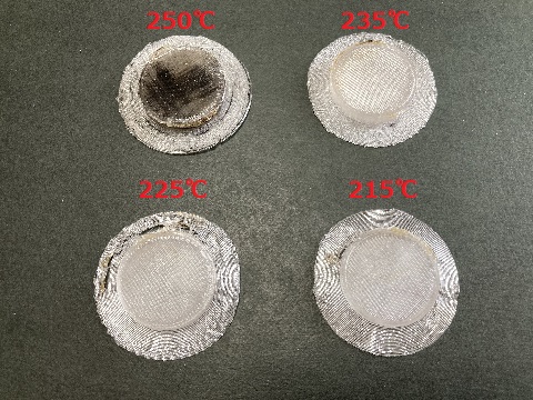
At first, I printed the test piece with highest possible temperature( 250 °C for PETG) as recommended in the article, but it caused deterioration of the material and printed parts was tinted brown. Maybe PETG was less heat resistant than ABS used in the referenced article.
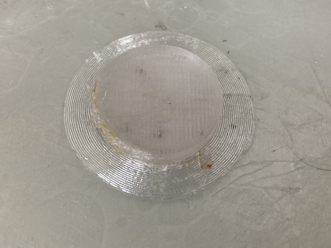
So I decreased the print temperature step by step and checked the best settings. The best result was, contrary to the recommendation of the referenced article, low-end, 215 °C( 5 °C lower than filament makers recommendation).
| Setting A | Setting B | Setting C(best result) | Normal setting | |
| Temperature | 250 °C | 235 °C | 215 °C | 225 °C |
| Infill | 120 % | 120 % | 120 % | 25 % |
| Layer height | 0.05 mm | 0.05 mm | 0.05 mm | 0.15 mm |
| Print speed | 20 mm/s | 20 mm/s | 20 mm/s | 30 mm/s |
Setting A: Printed at 250 °C and infill 120 %:
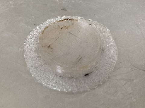
Setting B: Printed at 235 °C and infill 120 %:
Setting C: Printed at 215 °C and infill 120 %(best result):
Comparison:
Normal setting: Printed at 225 °C and infill 25 %:
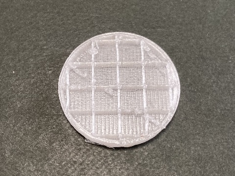
If infill setting smaller than 100 %, slicing software automatically generate inner structure like this.
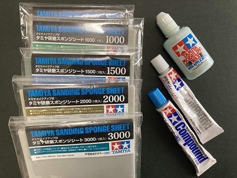
15.8 Post process
As a result of over-extrusion, the surface of the printed model is not smooth. So I should smoothed the surface with arious sanding/polishing materials.
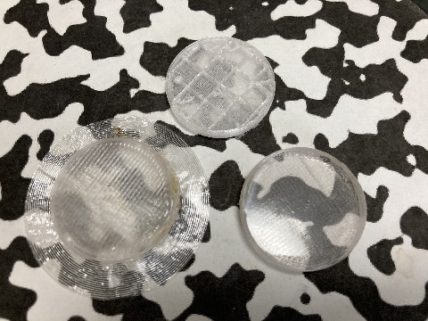
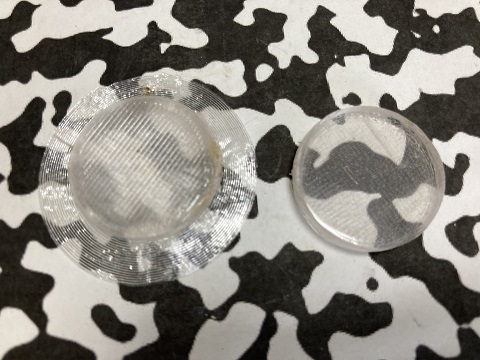
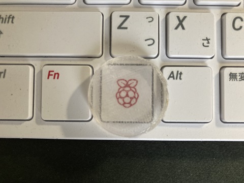
15.9 Result
The post process was time-consuming, but the end result was quite satisfying. Although sanding/polishing may be still inadequate…
15.10 Conclusion
To obtain transparent parts, it would be easier to use transparent UV resin with MSLA 3D printers or silicone molds. But it was good to show that it was also possible with FFF 3D printers.