11. Mechanical Design
This week we worked together on the group assignment of this week ‘Mechanical Design’.
11.0 Assignments of these weeks
11.0.1 Group assignment (WEEK1)
Design a machine that includes mechanism + actuation + automation
Build the mechanical parts and operate it manually
Document the group project
11.0.2 Individual assignment(WEEK1)
Document your individual contribution
11.0.3 Group assignment (WEEK2)
Actuate and automate your machine
Document the group project
11.0.4 Individual assignment(WEEK2)
Document your individual contribution
11.0.5 Learning outcomes
Work and communicate effectively in a team and independently
Design, plan and build a system
Analyse and solve technical problems
Recognise opportunities for improvements in the design
11.1 Group assignment (WEEK1)
11.1.1 Design a machine that includes mechanism + actuation + automation
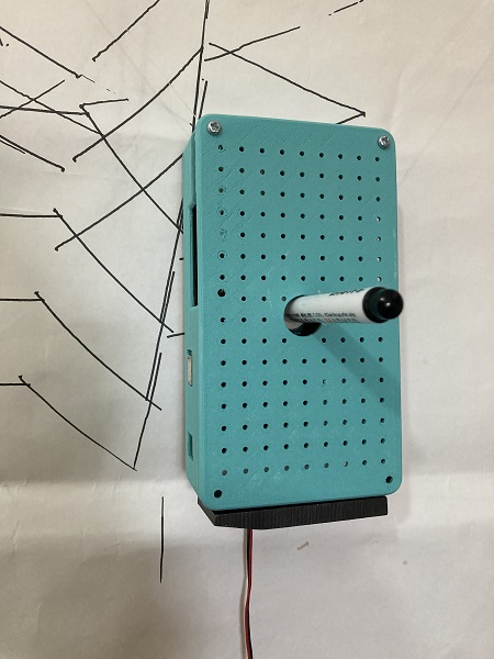
11.1.1.0 The object we built (semi-final image)
We built a ‘portable wall plotter’ controlled by a couple of small stepping motors and Arduino Uno built-in a box.
‘Almost finished’ project:
11.1.1.1 Project idea
We hoped to introduce a new digital-mechanical device to our lab. We checked devices which we haven’t introduced yet and found that we didn’t have a pen plotter.
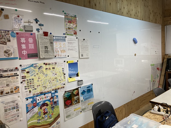
We decided to build a wall pen plotter hanging on the whiteboard because there was not enough space in our lab.
A large whiteboard in our lab:
Examples of wall pen plotters which we were inspired from:
How to make an OpenSource Vertical Plotter - Open Electronics
VERTICAL X-Y PLOTTER || DRAWING ROBOT || ARDUINO PLOTTER - Instructables
The Scribit Vertical Plotter Draws and Erases On Your Wall, Turning It Into a Huge Screen - Core77
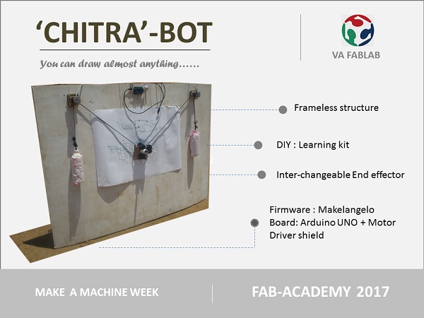
We also found a nice project in prior FAB academy:
2017/fablabvigyanashram
11.1.1.2 Source design
I(Yusuke) surveyed internet and found several articles about wall pen/brush plotters. Some of them were open source projects and came with detailed tutorials.
Typical layout of wall pen plotter is: motors and a control unit attached on the wall, a small pen holder hanging from the moter schafts by belts or wires.
But I found a rare sample which had all mechanism built in a pen holder body.
I liked it and I wanted to build my own…

:An image from The Scribit Vertical Plotter Draws and Erases On Your Wall, Turning It Into a Huge Screen - Core77
11.1.1.3 Source code
According to the tutorials, there are a couple of programs necessary for the wall pen plotter. One is a user interface program and the other is a firmware for the plotter.
I compared some tutorials and selected Makelangelo, because it was an open source project and both a user interface program and a firmware available.
11.1.1.3.1 User interface program for PC
Several versions of user interface programs of Makelangelo are available as source code on GitHub. I selected Makelangelo-7.28.2(newer stable version).
I decided to use a pre-compiled executable binary file instead of make and complie the source codes(I saved time for code check).
11.1.1.3.2 Firmware for the plotter
A firmware for Makelangelo is available as an Arduino sketch. Users need to modify the codes in order to fit the program with their own hardwares.
11.1.1.4 Mechanical design
Mechanical design of a wall pen plotter is rather simple. There are no gears, no links nor linear sliders but only pulleys and threads/wires.
But we hoped to integrate all mechanism in a small box, space-saving design was necessary.
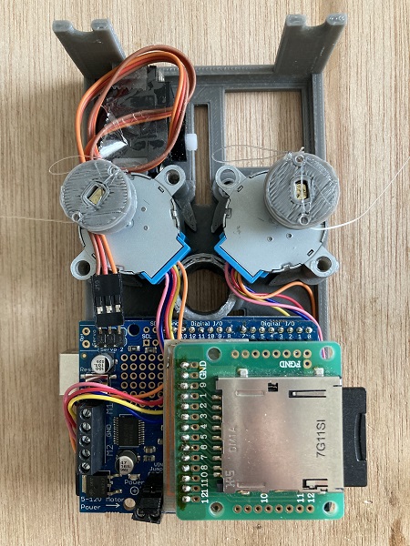
11.1.1.4.1 Key components
| Component | Function | Adopted product | Qty. |
| Stepping motor | Drive pulleys | CW-motor 28BYJ-48 | 2 |
| Motor driver | Power/control speed /direction of stepping motor(s) |
Adafruit Motor/Stepper /Servo Shield for Arduino v2 |
1 |
| Servo | Control pen position | FEETECH FS90 1.5kg analog 9g servo |
1 |
| Control unit | Control motor drivers(s) and servo | Arduino UNO | 1 |
| SD card shield | Read gcode data from SD card | Sunhayato CK-35 with a CNC-milled adapter board |
1 |
| SD card | Hand gcode data to the device | bulk | 1 |
| Regulated DC power supply | Power source | DAIWA PS-120M | 1 |
| Pulley | Wind-up/release threads | 3D-printed parts | 2 |
| Fishing thread | Hang and move the device on the wall | bulk | 2 |
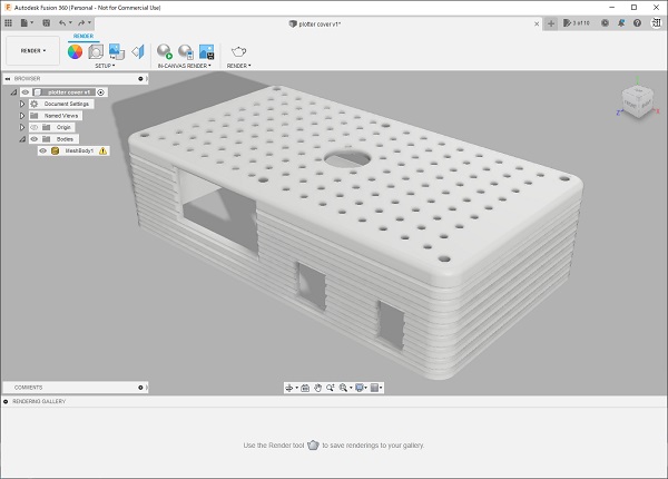
| Exterior | Protective cover | 3D-printed parts | 2 |
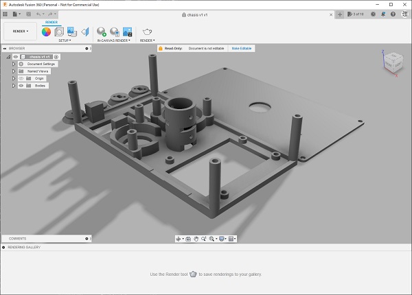
| Chasis | Mechanical frame | 3D-printed parts | 2 |
| Whiteboard marker | Plotting pen | bulk | 6 |
Chasis:
11.1.1.5 Exterior design
11.1.1.5.1 Design key
The design key of the exterior is Pop/Kitchenware. The designer used pastel colored filament to 3D-print the exterior.
Exterior:
11.1.2 Build the mechanical parts and operate it manually
Connected and drove stepping motors with Arduino(via separate motor drivers):
11.1.3 Document the group project
11.1.3.1 Role sharing of the members
We shared the roles as follows:
| Member | Position | Role |
| Yusuke Takahashi | Student | Concept/Mechanical design/Programming/Assembly/Test |
| Kohei Morimoto | Instructor | Technical review/Exterior design |
| Kazutoshi Tsuda | Instructor | Preparation of Group homepage |
11.2 Individual assignment(WEEK1)
11.2.1 Document your individual contribution
This page is it!
11.3 Group assignment (WEEK2)
11.3.1 Actuate and automate your machine
11.3.1.1 Programming
I spent several days for parsing, understanding, finding points to be modified, modifying and checking the modified code to work properly.
11.3.1.2 Assembly/Test
Completed chasis:
Test:
11.3.1.3 Calibration
Plotting a five pointed star:
More calibration shuold be necessary…
11.3.1.4 Demo
Plotting a spiral:
Calibration might be still not enough, but an interesting déformation effect was generated.
11.3.2 Document the group project
See group homepage.
11.4 Individual assignment(WEEK2)
11.4.1 Document your individual contribution
As an only student of our lab this year, I was in charge of concept design/mechanical design/programming/assembly/test/calibration/demonstration.