6. Electronics Design
This week I learned about Electronics design.
6.0 Assignment of this week
6.0.1 Group assignment
Use the test equipment in your lab to observe the operation of a microcontroller circuit board.
6.0.2 Individual assignment
Redraw an echo hello-world board. Add (at least) a button and LED (with current-limiting resistor). Check the design rules, make it, and test that it can communicate. Extra credit: simulate its operation
6.1 Customizing an echo hello-world board
I chose ATtiny45 again. It has only 8 legs and seemed to be soldered easily.
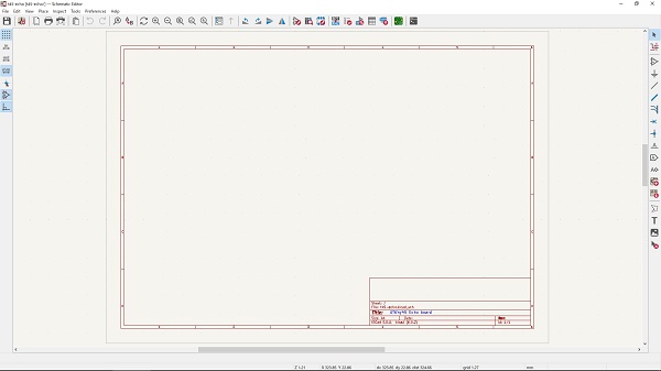
The original design:
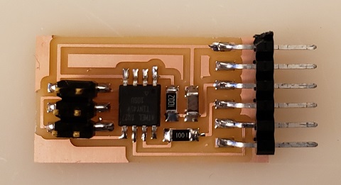
6.1.1 Redraw the board
I used KiCAD for redrawing the design. It was my first KiCAD experience, but relatively easy for me to learn the basic operation of KiCAD, thanks to the good tutorial.
In fact, I could create my first Gerber files in one day !
![]()
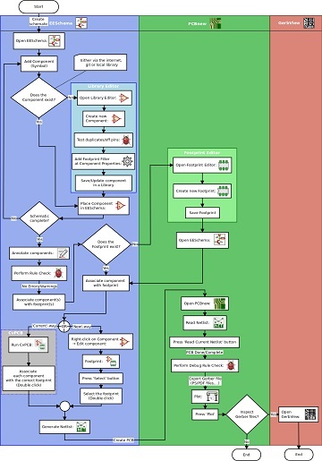
Operation flowchart of KiCAD:
Design steps:
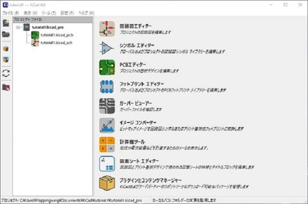
Start up menu:
Menu language set could be switched from one to others quite easily.
Schematic editor:
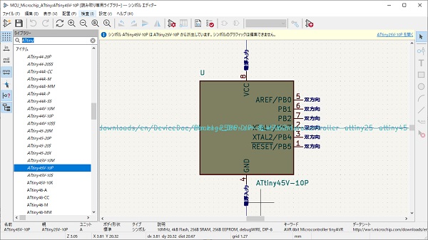
Symbol editor:
The symbol iibrary was very comprehensive and easy to use.
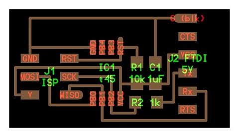
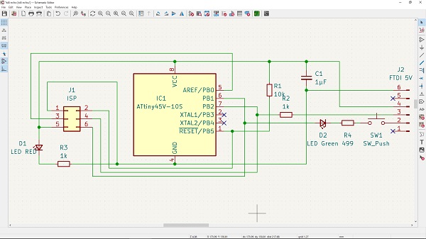
Design completed:
The schematic editor was easy to use.
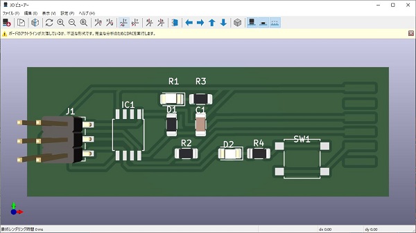
I added a couple of LEDs to the original design, one for power line and the other for Rx line. For Rx line, I also added a push switch, but it was not a good idea after all. I had to by-pass the switch when I connected the board to my PC.
6.1.2 Check the design rules
By clicking ‘Perform electrical rules check’ icon, any mistakes in the schema could be easily detected.

Errors indicated:
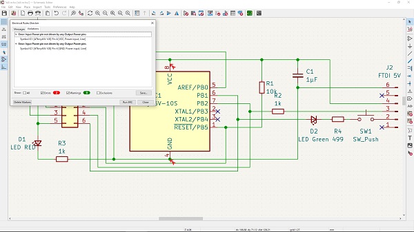
According to the error message, I added power flags to the schema:
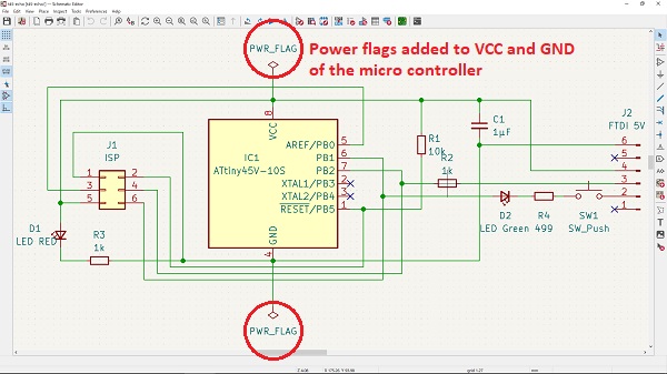
Errors disappeared after revision of the schema.
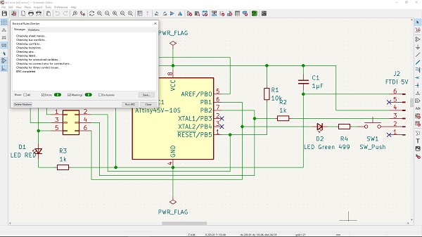
Finnaly the schema completed.

6.1.3 Create PCB pattern
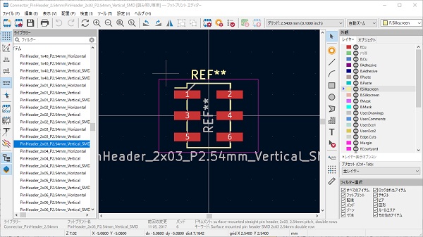
Footprint editor:
The footprint iibrary was also very comprehensive and easy to use.
PCB editor:
The PCB editor was easy to use.
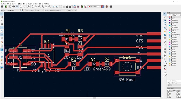
Filled zone added:

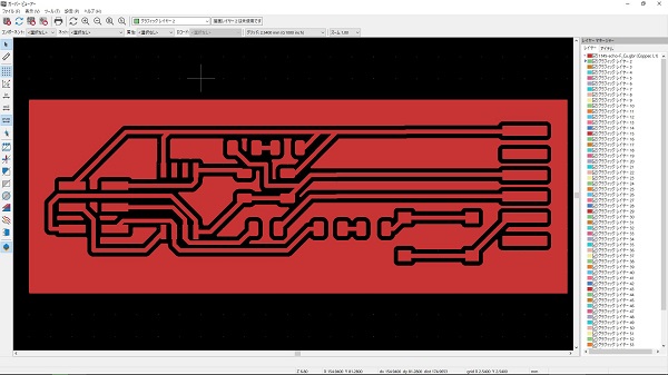
Gerber view:
3D viewer:
KiCAD files:
t45-echo.kicad_pro
t45-echo.kicad_sch
t45-echo.kicad_pcb
t45-echo-F_Cu.gbr
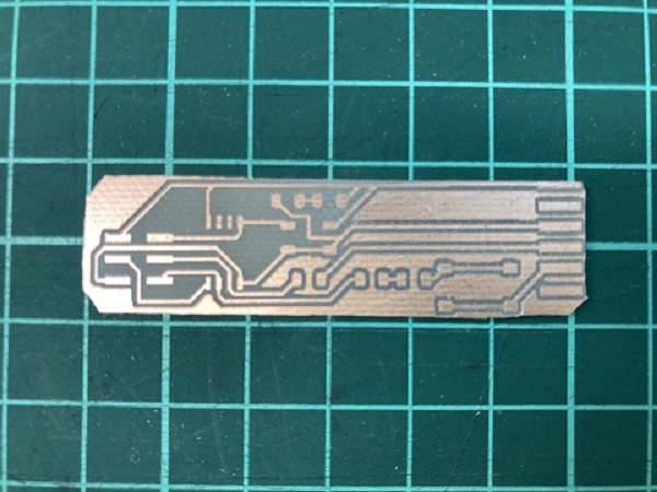
6.1.4 Make the board
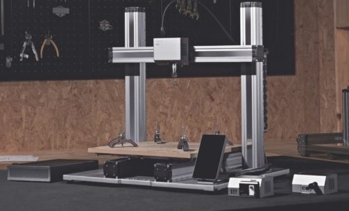
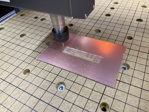
6.1.4.1 CNC milling:
For engraving the board, I used ‘Snapmaker 2.0’ again following to Week 04.
Tool settings:

6.1.4.2 Soldering:
Soldering was easy, because there were quite a few parts count.
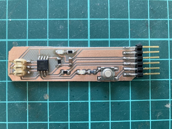
Parts used:
1x ATtiny45
1x 499Ω resistors
2x 1kΩ resistors
1x 10kΩ resistors
1x red LED
1x green LED
1x 1μF capacitor
1x Tactile switch
1x 2x3 pin header
1x 1x6 pin header
6.2 Program the board
6.2.1 Environment
For the ease of programming, I imported ATtiny Core library to Arduino IDE. Now I can write Arduino sketch for ATtiny.
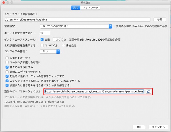

Library:
ATtinyCore by Spence Konde
libusb-win32
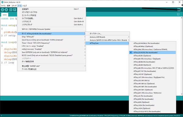
6.2.2 Test
Programming:
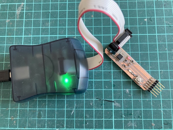
I used AVRISP Mk2 for programming the newly built board.
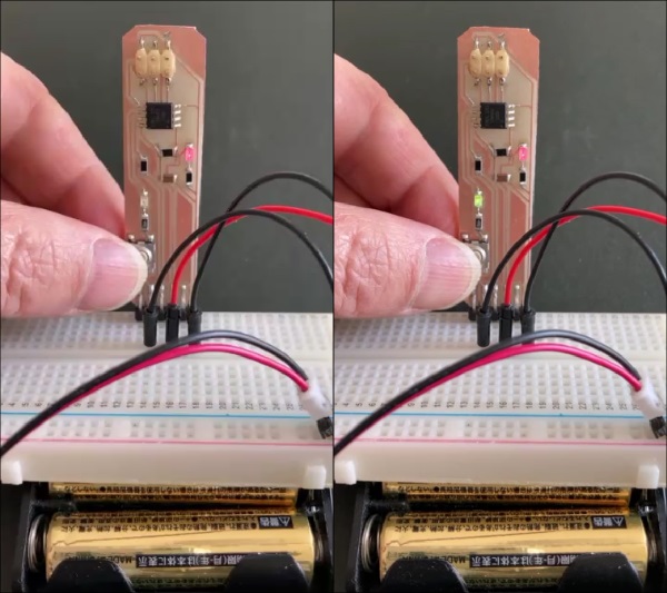
Blink:
I wrote a simple test program as an Arduino sketch. I made Green LED blink when I pushed a button. It worked well.
Sketch:
blink.ino
6.3 Observe the operation of a microcontroller circuit board(as group assignment)
6.3.1 Equipment
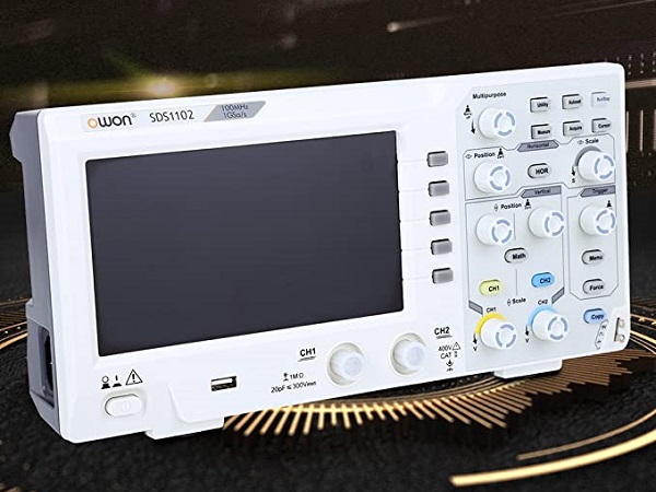
When Academy started, there was not any test equipments other than a handy multi meter in our lab, but my instructor kindly bought a brand-new digital oscillo scope for me.
It just arrived today(Mar 9) and I could use it.
SDS1102 digital oscillo scope:
6.3.2 Observe the operation
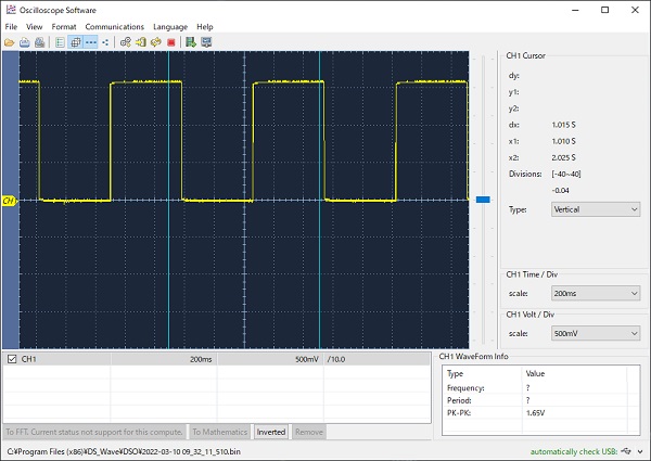
I wrote a simple test program for the board which I made this week. The program generates a regular PWM wave pattern. It worked well.
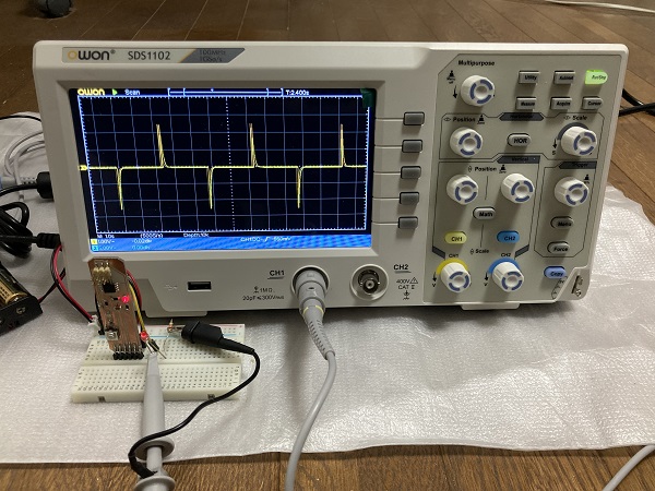
The software installed to PC can get data from the equipment:
Screen shot:
Sketch:
PWM_test.ino