3. Computer Controlled Cutting
This week was about computer-controlled cutting. It was very interesting, as I have used different programs and machines. First, I used Vynilcutter to cut Fabacademy 2022 in Armenian and a radiation logo. Then we have done our group project. And finally, I used my last week’s Freecad file to cut a parametric construction kit.
Here you can see our group project page for this week. My reflection for a group assignment can be found after the Vynil cutter section.
Vinyl Cutter
I started the week assignment by cutting a radiation logo and Fabacademy 2022 in Armenian with a Vinyl cutter. First, I read the manual.
![]()
.jpg)
.jpg)
.jpg)
Here, is the page where you can how to load Vynil. There is three modes for loading. 1. Roll, if you are loading a roll of Vynil. 2. Edge, if you are loading a roll of Vynil. 3. Piece, if you are loading a piece of Vynil.
.jpg)
Then, after reading the manual, I choose the piece option and loaded a piece of vynil, step by step as wriiten in the image above.
.jpg)
When the file was ready, I loaded a piece of a vinyl roll. Before cutting the file, I did a test cut to find the best value for the force parameter. You just need to push the test button.
.jpg)
As you can see image above, I cut a circle and rectangle inside it. This is the standard test cut of the Vynil cutter. You need to press a test button to cut it. To have a perfect cut the rectangle has to stay at its place after removing the circle.
.jpg)
.jpg)
After finding the best value for force, I set the page size and placed the logo and text to cut.
.png)
The final step is sending the file to the printer and cut.
.jpg)
.jpg)
Laser Cutter Kerf
For finding the laser cutter Kerf, we have cut two squares from cardboard. One was 15mm x 15mm, and one was 10mm x 10mm. Then we measured these with a micrometer. The micrometer is a device for measuring very small objects, so it is a very precise tool. But before cutting, we focused laser and made some tests on cardboard to find the best values for speed, power and rate.
.jpg)
.jpg)
.jpg)
The metallic part is dedicated to focus the laser manually. After the setting of the focus, you should rotate it.
.jpg)
Then we cut two squares.
.jpg)
.jpg)
We have measured it with a micrometer.
.jpg)
In the case of the 10mm square the measurement was 9.78mm so the kerf is (10-9.78)/2=0.11mm In the case of the 15mm square the measurement was 14.71mm so the kerf is (15-14.71)/2=0.145mm. The slight difference between kerf can be explained as a result of not ideal material. Our cardboard was not ideal, it is curved so the focal point changes depending on where exactly the laser cuts.
Parametric Construction Kit
The most interesting part for me was cutting a parametric construction kit. I used my last week’s assignment. Then, I used Openscad to make the tolerance test comb.
Last week, I sketched a parametric drone body. This week, I realized that I can make a construction kit with the same design.
.png)
Then, I designed the tolerance test comb with Openscad. I tried to make it fully parametric, as we have materials with different thicknesses. So, we can use test comb for shopbot jobs too.
.png)
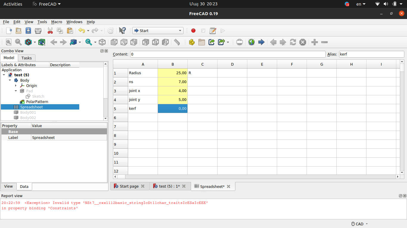
Here we have six parameters.
- Length
- Width
- Number of joints
- Joint x
- Joint y
- Size of steps
Having six parameters, you can change the test comb as you wish. For these types of designs, Openscad is very easy and fast. At the end of the code, you can see projection(cut = true) command, which I used to make a design in 2D and export it.
Our material for cutting was cardboard with a thickness of 4mm. So, I set the parameters
- length = 100
- width = 25
- num = 10
- j_x = 4
- j_y = 10
- step = 0.05
Having the design done, I start to cut.
.png)
.png)
For cutting, I used Corel-draw as I had an issue with Inkscape. Epilog laser refused to cut from Inkscape, I have tried everything from Google, but I have had no success. As you can see from the image above, I did raster as well.
The result
.jpg)
.jpg)
After having two test combs, I did a tolerance test. The best matching size was 3.8 mm. Please notice that our kerf was 0.11mm to 0.145mm and if we take into count both sides we will have 0.22mm to 0.29mm. Having the joint parameter, I set it in Freecad.

Then, I made three solid bodies with a different number of sectors (3, 4, 7).
I exported .svg file and used Corel-draw to arrange parts and cut.
.png)
Finally, I got a parametric construction kit, which can be assembled in different ways.
.jpg)
.jpg)