13. Networking and communications
This week’s assignment is about networking and communications below you can see our group and individual assignments.
Group assignment.
send a message between two projects
My individual assignment covers sending messages between two boards. My board from Output Devices week sends a number via RF module to the Arduino board.
Link for the group assignment page.
Individual assignment.
design, build and connect wired or wireless node(s) with network or bus addresses
For this week I tested the NRF24L01 radio module with my board from Output devices week. I connected one module to my board and the other one to the Arduino Uno. My board is the transmitter and Arduino is the receiver.
NRF24L01
The NRF24L01 is a radio transceiver that works at 2.4Ghz-2.5Ghz frequencies. Here you can see some shots from the datasheet to get more information about NRF.
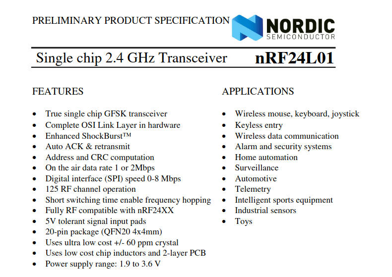
You can look at the image above and see that the package of NRF24 is very small, so I decided to use an already designed commercial radio module that uses NRF24 you can see the image of the module below.

Testing NRF24
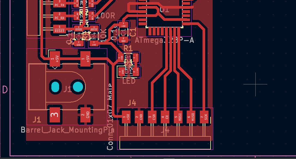
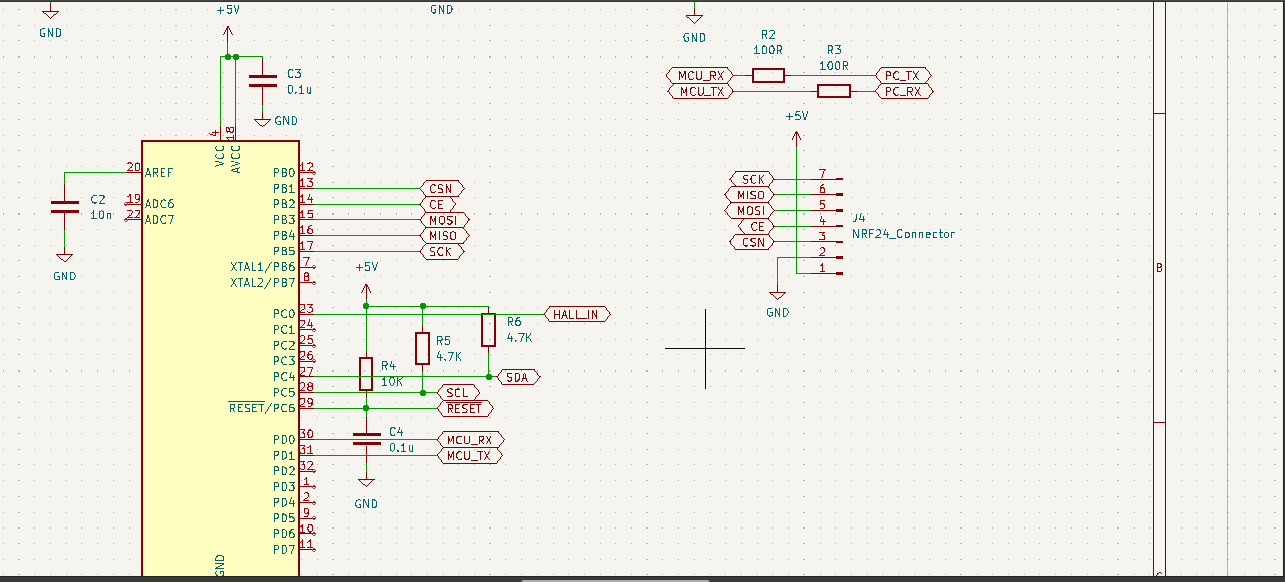
To interface this module with my board and with the Arduino I read this really helpful tutorial. Below you can see the schematic and layout parts of my PCB that are designed to interface with this module.
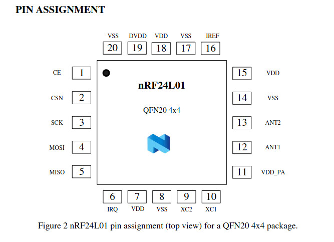
Below you can see the pinout of the NRF24L01 module.

As you can see it uses SPI to communicate. I have a connector in my board to communicate with it the only problem is that I didn’t notice that the module needs a 1.9V - 3.3V power source and I didn’t put a 3.3v voltage regulator in my design. I will fix it and mill another one for my final project, but at this point, I am going to power it from Arduino Uno. Here is my setup to test the module.
![]()
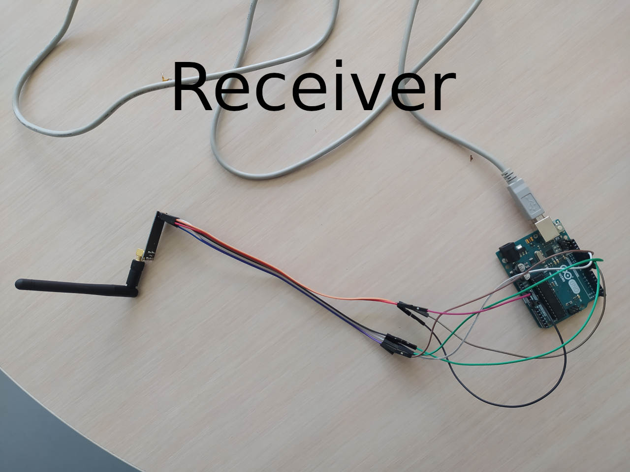
As you can see from an image I am using Arduino with my board, but Arduino is used only to power up the RF module.
Basically what I did is that I used my board as a transmitter and an Arduino as a receiver. I used codes from the tutorial and modified them a bit. You can see the codes below.
Transmitter Code
//Include Libraries
#include <SPI.h>
#include <nRF24L01.h>
#include <RF24.h>

//create an RF24 object
RF24 radio(9, 10);  // CE, CSN

//address through which two modules communicate.
const byte address[6] = "00001";

int counter = 0;

void setup()
{
  Serial.begin(9600);
  Serial.println(radio.begin());

  //set the address
  radio.openWritingPipe(address);

  //Set module as transmitter
  radio.stopListening();
}
void loop()
{
  //Send message to receiver
  counter++;
  char text[32] = "";
  sprintf(text,"counter = %d",counter);
  radio.write(text, sizeof(text));

  delay(1000);
}
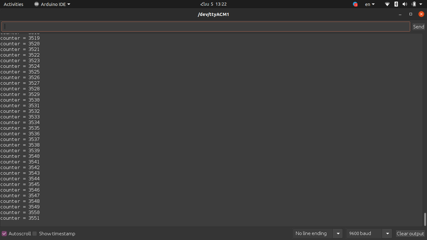
There is a variable called “counter”, it is incrementing at each iteration and my board sends the value to the receiver. Here is the receiver code.
Receiver Code
#include <SPI.h>
#include <nRF24L01.h>
#include <RF24.h>

RF24 radio(9, 10); // CE, CSN

const byte address[6] = "00001";

void setup() {
  Serial.begin(9600);
  delay(1000);
  Serial.println(radio.begin());
  radio.openReadingPipe(0, address);
  radio.setPALevel(RF24_PA_MIN);
  radio.startListening();
}

void loop() {
  if (radio.available()) {
    char text[32] = "";
    radio.read(text, sizeof(text));
    Serial.println(text);
  }
}
The receiver board just takes whatever it receives and prints it on the serial monitor. Below you can see the screenshot of the serial monitor.
So, having successfully tested radio modules I am going to use them in final project. I will send the speed of the wind using them.