12. Input Devices
This week’s assignment is about input devices below you can see our group and individual assignments.
Group assignment.
probe an input device’s analog levels and digital signals
Below you can see the video in which we are measuring the output of the A1324 Hall effect sensor.
Datasheet of the sensor.
Link for the group assignment page.
Individual assignment.
measure something: add a sensor to a microcontroller board that you have designed and read it
The Input Device
For this week my assignment is to connect an input device to a board that I have designed. As I already mentioned in Ouput device week, I have designed the first version of my final project’s PCB and I am testing inputs and outputs during these weeks, and I am going to test the RF module in Networking and Communication week. So, the design of the board is the same. For this week I tested the A1324 hall effect sensor. I wrote a program that measures how many times a magnet passed the hall effect sensor.
A1324 datasheet
So, before designing a PCB I read the datasheet of A1324, to be sure about packaging, input voltages and output signals. Below you can see the feature description and packages of A1324.
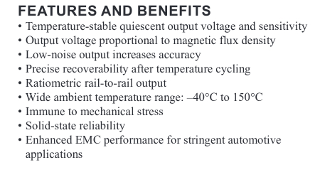

Here you can see pinout of sensor.

You can observe from the images above that the right package is one that I have. I also outlined output properties from a datasheet to exactly know what I should expect to have on the output pin of this sensor.

Looking at the plots above we can see that in normal conditions when the ambient temperature is 25 degrees and there is no magnetic flux the output voltage should be approximately 2.4 V.
Schematic and Layout
In this section, I am going to show the part of the schematic that relates to A1324 and the layout part that relates to the sensor.
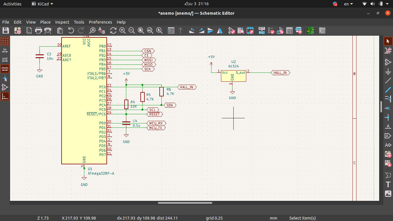
You can see that it is not complicated and I connected the output pin of the sensor directly to the MCU’s PC0 pin which is the A0 pin for Arduinos. I was a bit afraid that because of the direct connection it would be noise but tests showed me that there is no need for extra components. Below you can see the layout part.
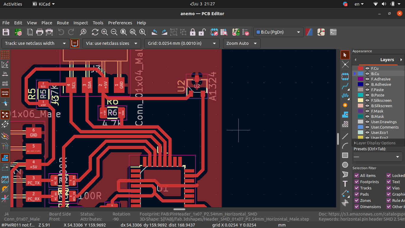
There is nothing special in the layout, the only thing is that I intentionally placed it near the edge of the PCB, I am going to design the anemometer in a way that the wing with a strong magnet should pass through the top of the sensor. So, I placed it further from other electronic components to avoid interference with the magnetic field that the magnet creates. The next part is about programming and testing.
Programming and Testing
It was really interesting for me, I wrote a program that counts how many times the magnet passed the top of the sensor in a second and prints it on LCD. Below you can see the Arduino code.
#include <Wire.h>
#include <LiquidCrystal_I2C.h>

LiquidCrystal_I2C lcd(0x27,20,4);  // set the LCD address to 0x27 for a 16 chars and 2 line display

int hall_in = A0;  // Analog input pin

int val = 0; // value of adc channel
int count = 0; // Counter to count the number of iteretions
int mag_tick = 0; // Counter to count how many times magnet passed the sensor
int wind_speed = 0; // How many times the magnet passed the sensor in one second
bool passed = 0; // A flag that is being set when magnet passes the sensor

void setup()
{
  Serial.begin(9600);
  lcd.init();                      // initialize the lcd
  lcd.init();
  // Print a message to the LCD.
  lcd.backlight();
  lcd.setCursor(1,0);
  lcd.print("hello everyone");
  lcd.setCursor(1,1);
  lcd.print("BAREV BOLORIN");
  delay(5000);
  DDRB = 0b00000100;  // Setting PINB2 to be input
  PORTB = 0b00000100; // Setting PINB2 to HIGH state
  lcd.setCursor(1,0);
}


void loop()
{
  PORTB = 4 - PORTB; // Toggleing the PINB2
  val = analogRead(hall_in); // Reading sensor's output

  // Checking is there is magnet or no
  if(val < 500 && passed == false)
  {
    mag_tick++;
    passed = true;
  }
  else if(val > 500 && passed == true)
  {
    passed = false;
  }

  count++; // counting interetion

  // if count >= 4000 then it is one second
  if(count >= 4000)
  {
    wind_speed = mag_tick;
    mag_tick = 0;
    count = 0;

    lcd.clear();

    lcd.print(wind_speed);
  }
}
There is a part of the code that toggles PINB2. I did it to exactly measure how many iterations MCU does during one second with the help of an oscillograph. I didn’t use the digitalWrite() function to make it work faster.

I measured the frequency of the signal that was generated by the PCB. As an image shows the frequency is 4.4Khz and that’s why I put 4000 as one second in the code.
Below you can watch the video of my board working.