6. Electronics design
This week I was working on the hello-world board. As I have already designed a programmer with samd11c, I just modified that design and added a led and a button. I also used the connector for the target board to have tree input/output pins.
Our assignment for this week is
Group assignment.
use the test equipment in your lab to observe the operation of a microcontroller circuit board
Individual assignment.
- redraw an echo hello-world board,
- add (at least) a button and LED (with current-limiting resistor)
- check the design rules, make it, and test that it can communicate
- extra credit: simulate its operation
Group Assignment
For the group assignment, we did some measurements using different equipment from Fablab. First, we used the multimeter. It is a handy tool for finding short circuits or measuring resistance and capacitance. Then we used an oscilloscope and signal generator.
Board Design
In electronics production week, I designed a programmer with samd11c from scratch. So, for this week, I just modified that design. Below you can see the final version of a programmer board schematic.
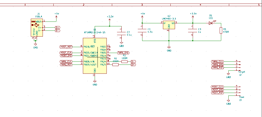
I changed several things:
- I changed the target programming pins to have three input/output pins.
- I disconnected led_1 from a 3.3V source and connected the microcontroller pin.
- Added a button with a pull-down resistor.
Here you can see the schematic changed.

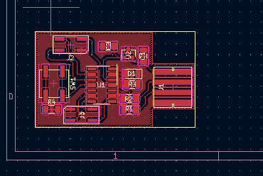
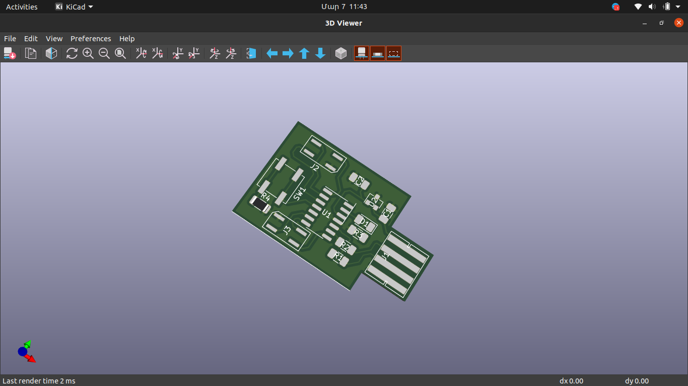
Then I assigned the footprint for a button and modified the layout design.
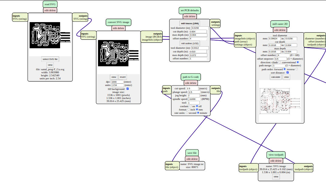
Finally, I used mods to generate Gcode files for SRM-20.
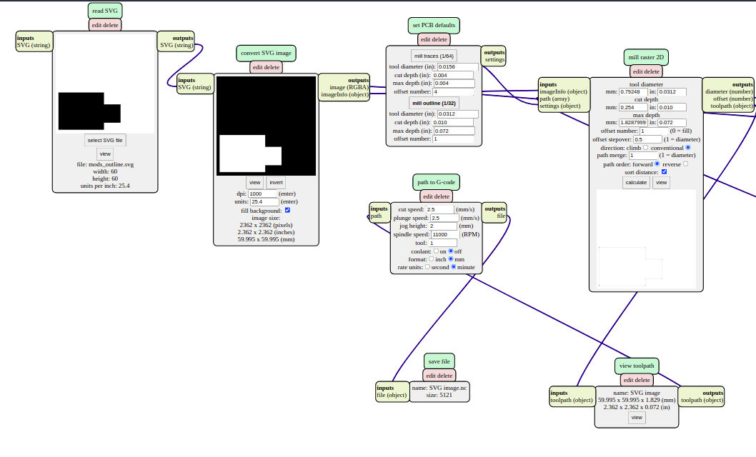
The first try was a failure because I forgot to set minimal track clearance, so the tracks for USB and a button were connected. I changed the design a little bit and tried one more time. The second try was successful. Having PCB cut, I assembled it.
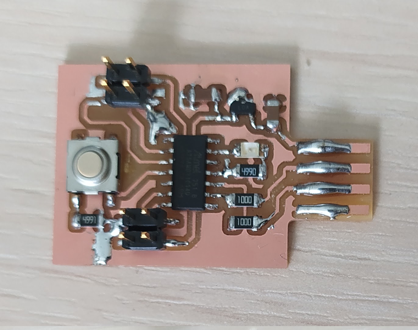
After assembly, I used multitester to check board connections and shorts. I used the programmer from the previous week to program the board. I did a small research and found out that I can burn a bootloader to the board and use it directly with Arduino IDE. So, I used the programmer one time to burn a bootloader. I used a tutorial from Adrian Torres’s SamdIno website page.
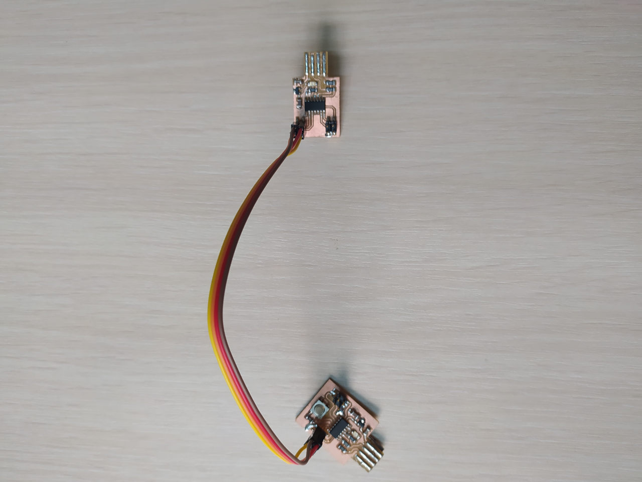
I used my programmer to burn the bootloader.
Then I did same steps as for programming my programmer the only change is the file that I used to program. I downloaded the .bin file for Arduino bootloader from here. Then used same commands in terminal to burn it.
You need to copy sam_ba_SAMD11C14A.bin file to the EDBG folder and use this command.
sudo edbg -b -t samd11 -pv -f sam_ba_SAMD11C14A.bin
And that’s it.
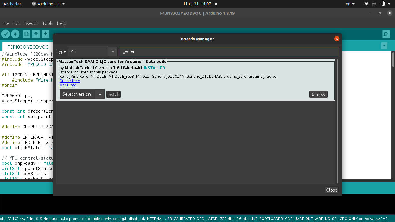
Then you need to open Arduino IDE and install generic board package for samd11c.
I wrote a simple program that turns on led and sends a “Button Pressed” text via serial communication when you press button and does the oposite when button isn’t pressed.
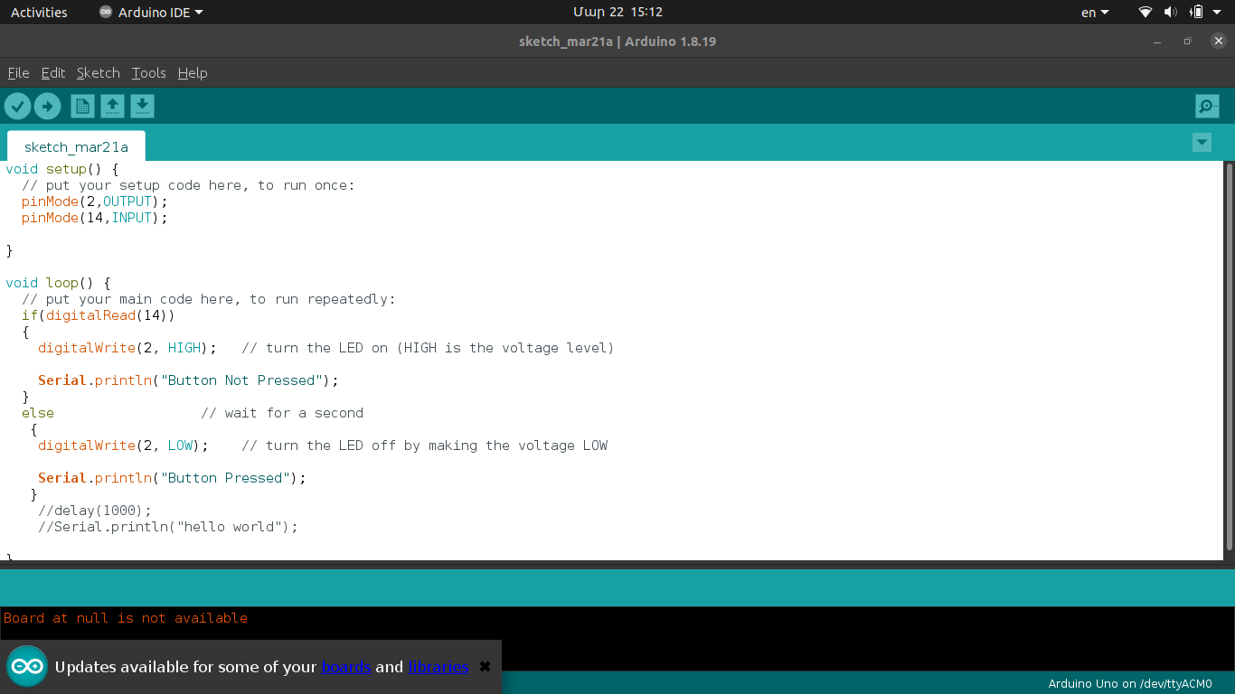

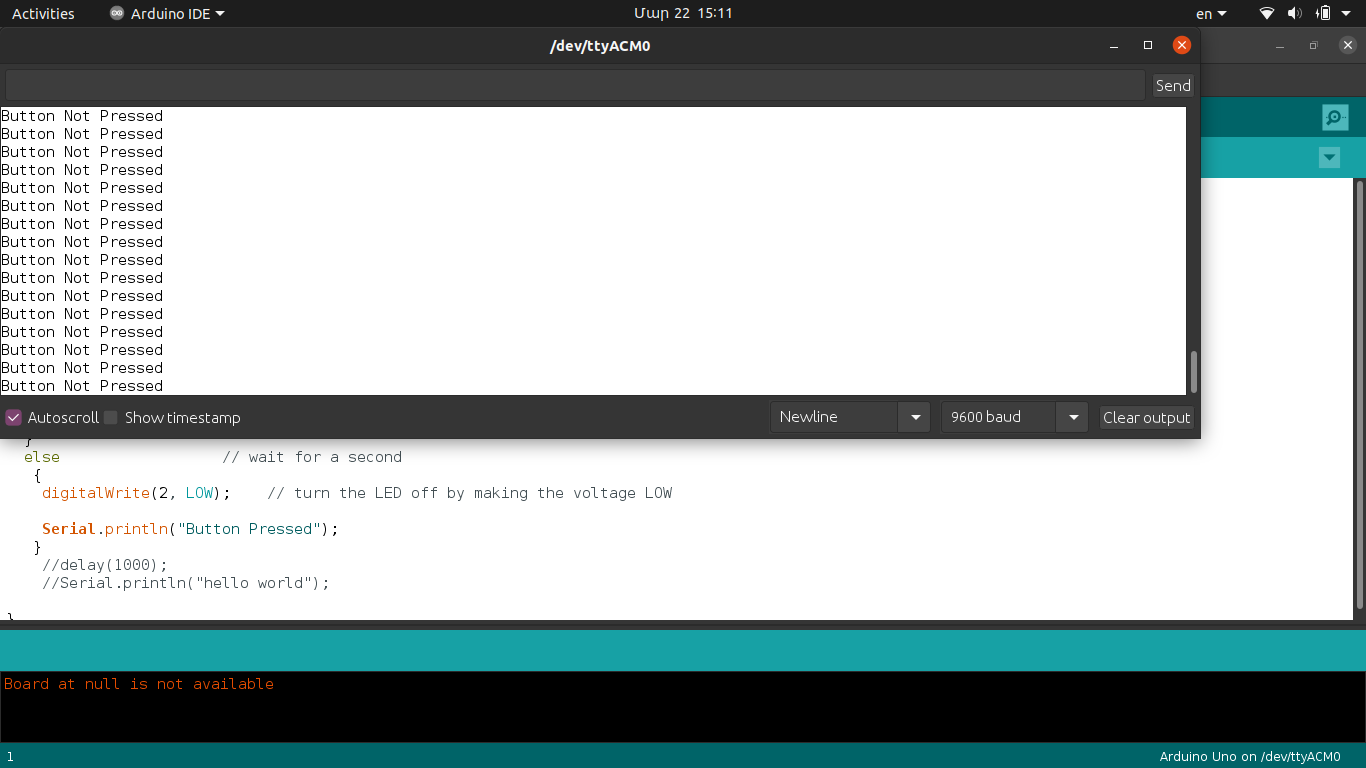
Below you can see a short video how the board works.