11. Mechanical Design, Machine Design
This week’s assignment is about output devices below you can see our group and individual assignments.
Our assignment.
PART 1 Group assignment: Design a machine that includes mechanism + actuation + automation Build the mechanical parts and operate it manually. Document the group project
Individual assignment: Document your individual contribution.
PART 2
Group assignment: Actuate and automate your machine. Document the group project
Individual assignment: Document your individual contribution.
For this week’s assignment, we decided to collaborate with Kannai, Japan. We designed and made a stopwatch that works with a stepper motor. My individual contribution was electronics and programming part mostly. Below you can see the short video of the machine working.
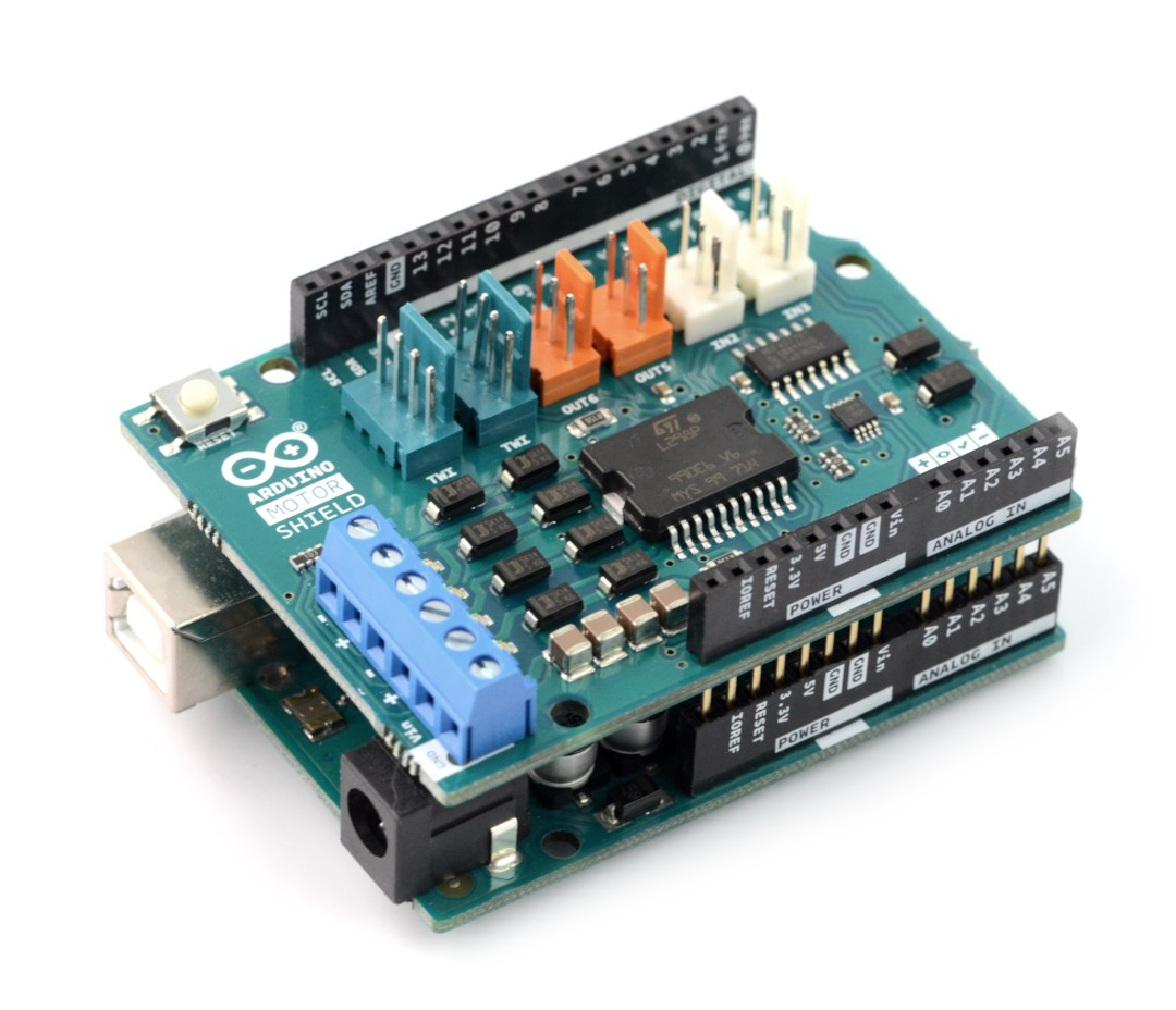
The electronics part isn’t complicated. I used Arduino UNO and the motor driver shield to drive the stepper and a switch to detect the end of time. Logic is simple if a switch is not pressed stepper does a step that corresponds to one second until the switch is pressed. Below you can see the Arduino code.
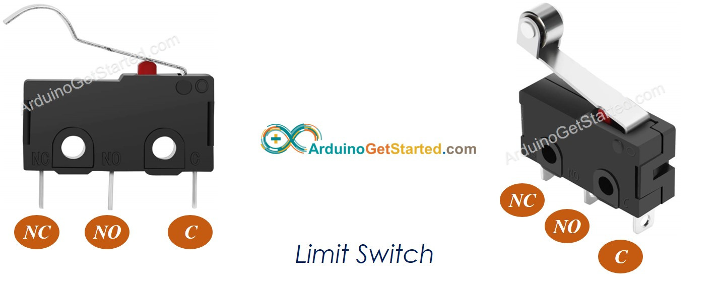
We also used a limit switch to detect the end of time.
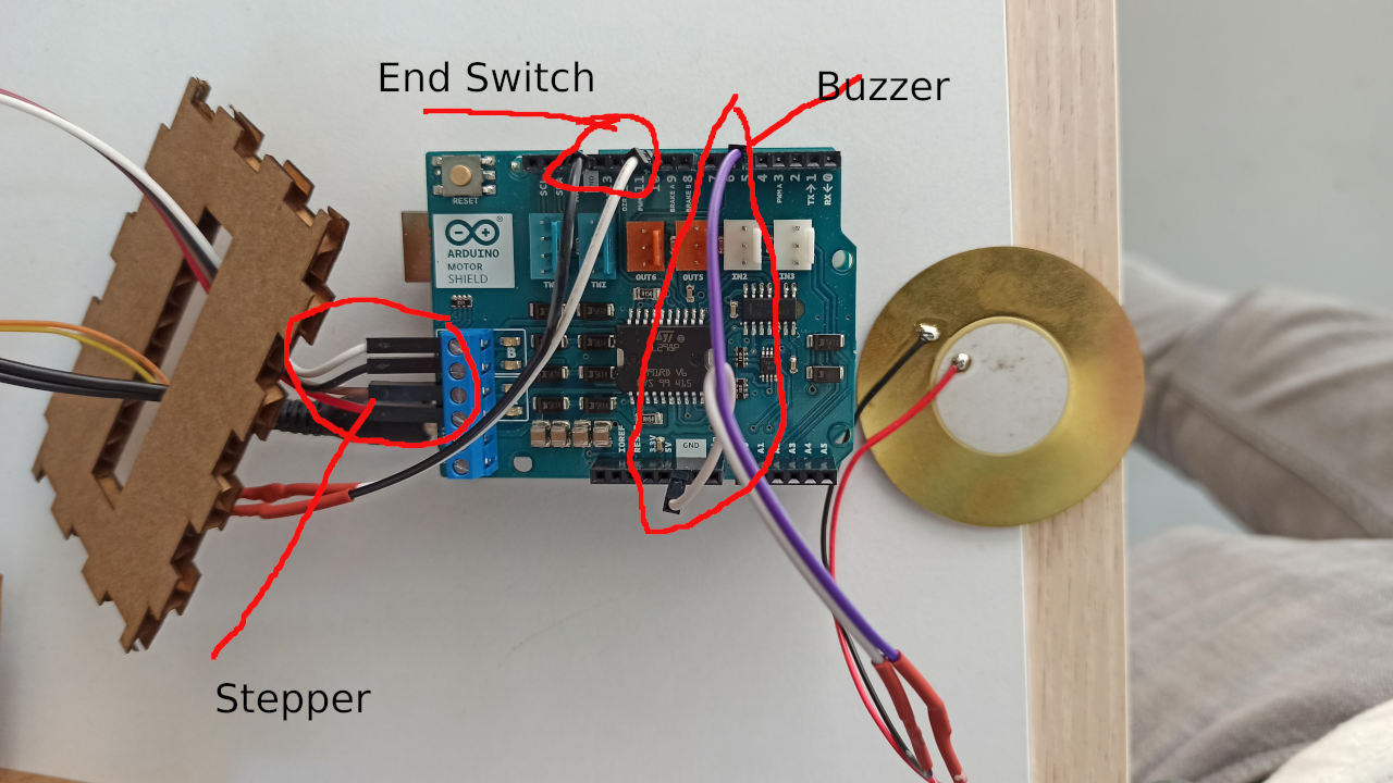
I connected the switch to the 10th pin of Arduino. The pin is pulled up when the switch is pressed pin goes low and the program stops turning the motor.
Below you can see the Arduino code. I used this link for reference but edited the original code for our needs
int delaylegnth = 10;//stepper step etc...
int interval = 1200; //seconds interval
int buttonState = 0;


void turn() {
  digitalWrite(9, LOW);  //ENABLE CH A
  digitalWrite(8, HIGH); //DISABLE CH B

  digitalWrite(12, HIGH);   //Sets direction of CH A
  analogWrite(3, 255);   //Moves CH A

  delay(delaylegnth);

  digitalWrite(9, HIGH);  //DISABLE CH A
  digitalWrite(8, LOW); //ENABLE CH B

  digitalWrite(13, LOW);   //Sets direction of CH B
  analogWrite(11, 255);   //Moves CH B

  delay(delaylegnth);

  digitalWrite(9, LOW);  //ENABLE CH A
  digitalWrite(8, HIGH); //DISABLE CH B

  digitalWrite(12, LOW);   //Sets direction of CH A
  analogWrite(3, 255);   //Moves CH A

  delay(delaylegnth);

  digitalWrite(9, HIGH);  //DISABLE CH A
  digitalWrite(8, LOW); //ENABLE CH B

  digitalWrite(13, HIGH);   //Sets direction of CH B
  analogWrite(11, 255);   //Moves CH B

  delay(delaylegnth);
}
void setup() {
  pinMode(10, INPUT);
  //establish motor direction toggle pins
  pinMode(12, OUTPUT); //CH A -- HIGH = forwards and LOW = backwards???
  pinMode(13, OUTPUT); //CH B -- HIGH = forwards and LOW = backwards???

  //establish motor brake pins
  pinMode(9, OUTPUT); //brake (disable) CH A
  pinMode(8, OUTPUT); //brake (disable) CH B
  pinMode(5, OUTPUT); //buzzer

}

void loop(){

  buttonState = digitalRead(10);

  while (buttonState == HIGH)
  {
    turn();
    turn();
    turn();


    delay(interval);
    buttonState = digitalRead(10);

  }

  while (buttonState == LOW)
  {
    digitalWrite(5, LOW);  //ENABLE CH A
    delay(1);
    digitalWrite(5, HIGH); //DISABLE CH B
    delay(1);
    buttonState = digitalRead(10);
  }


}