Final Project

So my final project is the digital anemometer. The idea is that the anemometer should measure speed of wind send it through RF to the PC.
WHAT DOES IT DO
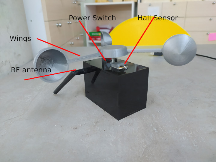
Anemo is a device, that uses a hall effect sensor, magnet, wings and MCU to measure wind speed, then sends it to the PC using RF module. Below you can see the image.
WHO HAS DONE WHAT BEFOREHAND
There are lots of examples of digital anemometers, but the difference is that it should work with the set of anemometers.
WHAT DID YOU DESIGN
I designed PCB, wings to measure speed, a packaging box from acrylic and interface software to connect it with the PC.
PCB Design
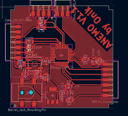

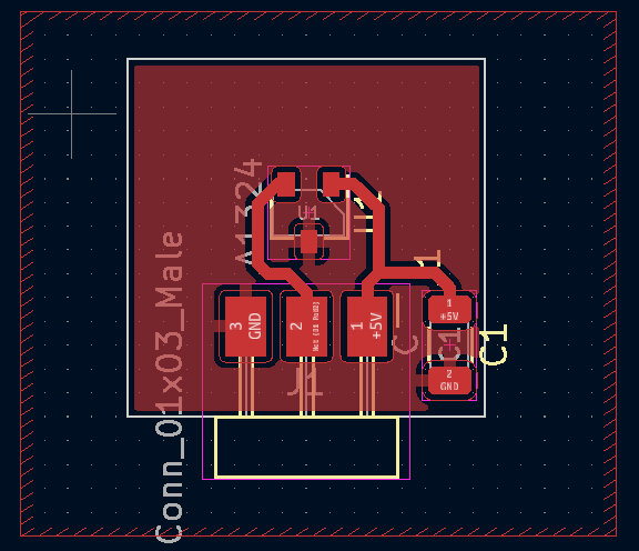
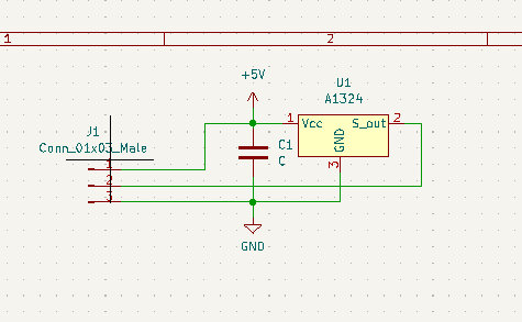
This PCB is not the first version I was working on it in Output devices week also. After output, input and networking weeks I redesigned it and fixed all mistakes. For the hall effect sensor, I designed another PCB only for the sensor.
Below you can see the images of the main PCB milled and then assembled.


Then I designed a package box using an online box generator. And placed the 9V battery, main PCB and power switch in it.

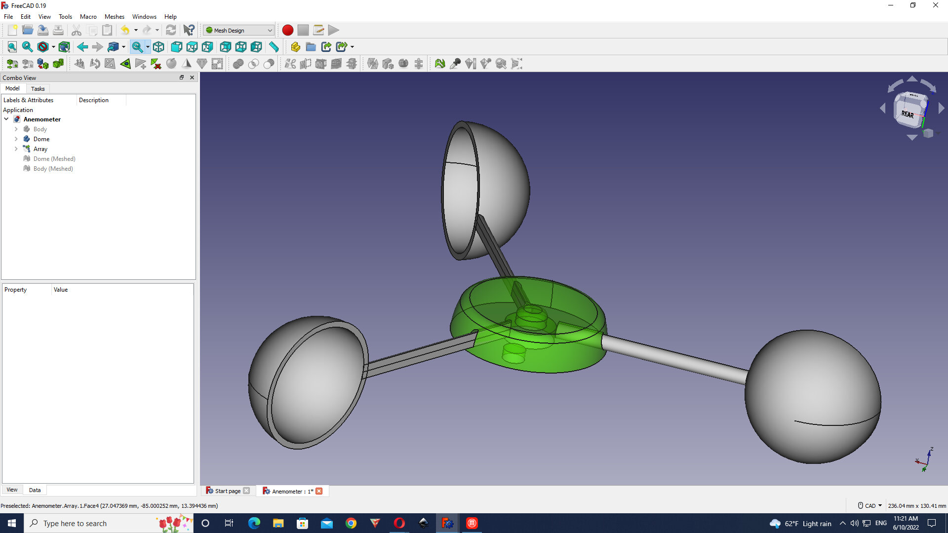
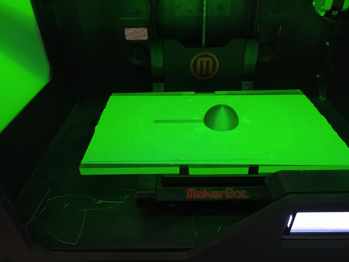
For the wings, I used Freecad to design them.

Finally, when everything was assembled I wrote the code for Arduino and used the interface that I designed in Interface and application week. Also, I used my work from Input and Networking weeks. Below you can see the code.
#include <SPI.h>
#include <nRF24L01.h>
#include <RF24.h>


//create an RF24 object
RF24 radio(9, 10);  // CE, CSN

//address through which two modules communicate.
const byte address[6] = "00001";

int hall_in = A0;

int val = 0;
int count = 0;
int mag_tick = 0;
float wind_speed = 0;
bool passed = 0;


void setup()
{
  Serial.begin(9600);
  pinMode(13,OUTPUT);
  Serial.println(radio.begin());

  //set the address
  radio.openWritingPipe(address);

  //Set module as transmitter
  radio.stopListening();
}


void loop()
{
  val = analogRead(hall_in);
  //Serial.println(val);

  if(val > 511 && passed == false)
  {
    mag_tick++;
    passed = true;
  }
  else if(val <= 510 && passed == true)
  {
    passed = false;
  }
  count++;
  if(count >= 9000)
  {
    wind_speed = (float)mag_tick * 0.628;

    count = 0;
    //send speed with RF

    char text[32] = "";
    sprintf(text,"%d",(int)(wind_speed * 100));
    radio.write(text, sizeof(text));
    mag_tick = 0;
    PORTB = 32 - PORTB;

  }
  //delay(1);
}
WHAT MATERIALS AND COMPONENTS WILL BE USED
WHERE WILL THEY COME FROM
HOW MUCH WILL THEY COST
For all these questions I will write the BOM of materials.
| Name | Value | Description | Price | Qty | Vendor |
|---|---|---|---|---|---|
| Capacitor | 0.1u | 1206 SMD Ceramic Capacitor | ~0.1$ | 5 | Digikey.com |
| Capacitor | 22u | 1206 SMD Ceramic Capacitor | ~0.1$ | 1 | Digikey.com |
| Capacitor | 10n | 1206 SMD Ceramic Capacitor | ~0.1$ | 1 | Digikey.com |
| LED | RED | 1206 SMD LED | ~0.1$ | 2 | Digikey.com |
| POWER Jack | Connector:Barrel_Jack | ~0.1$ | 1 | Digikey.com | |
| Resistors | 1K,4.7Kx2,100R x2,470R | 1206 SMD resistor | ~0.1$ | 6 | Digikey.com |
| Voltage Regulator | 5V | LM2940 LDO 5V regulator | ~0.5$ | 1 | Digikey.com |
| Voltage Regulator | 3.3V | LM3480 LDO 3.3V regulator | ~0.5$ | 1 | Digikey.com |
| MCU | Atmega328p | TQFP32 8Mhz 8 bit microcontroller | ~1.5$ | 1 | Digikey.com |
| RF module | NRF24L01 | 868Mhz radio tranceiver | ~1.5 $ | 1 | Online shop |
| Power Switch | ON/OFF RED switch | ~0.5$ | 1 | Online shop | |
| Acrilic | 3mm thickness, black 0.4mx0.15m | ~3.5$ | From shop in Yerevan | ||
| Duracell battery | 9V | ~2$ | 1 | Any Shop in Armenia | |
| PLA for 3D print | Color: Grey | ~2.5$ | 0.3Kg | Online shop |
WHAT PARTS AND SYSTEMS WERE MADE
The main PCB, package box, and wings.
WHAT PROCESSES WERE USED
- 3D printing(wings)
- 2D milling(PCB)
- Laser cutting (Box)
WHAT QUESTIONS WERE ANSWERED
- The accuracy of measurement. 0.62 m/s is the accuracy of the Anemometer
- The distance of radio communication. Approximately 100m
- Tolerance under strong wind. It can handle wind speeds up to 70km/h.
- Is there an opportunity to use more sensors with the same MCU? Yes, there is many input/output pins that are free now and can be used for other sensors and output devices.
WHAT WORKED, WHAT DIDN’T?
The main parts of the project worked, for example, the rf module worked perfectly as well as the hall effect sensor, but I was planning to have more sensors like temperature, humidity, etc. Because of shortage of time, I didn’t manage to add those sensors.
HOW WAS IT EVALUATED
The project was evaluated in different stages. The first stage was evaluated by me. I checked all parameters, whether it measures correctly, is data received by PC is being stored in CSV file, etc. The Second stage was evaluated by Babken. He checked whether it meets all requirements of the task or not. And the final stage was the presentation to Neil.
Downloads
License
CC BY: This license allows reusers to distribute, remix, adapt, and build upon the material in any medium or format, so long as attribution is given to the creator. The license allows for commercial use. CC BY includes the following elements: BY – Credit must be given to the creator