5. 3D Scanning and printing
This week I worked on the 3D design, 3D scanning, and defining design rules for our 3D printers. Our assignment consists of two parts, group assignments and individual assignments.
Our assignment for this week is
Group assignment.
test the design rules for your 3D printer(s)
You can find our group project page for this week here.
Individual assignment:.
design and 3D print an object (small, few cm3, limited by printer time)that could not be made subtractively
3D scan an object (and optionally print it)
Testing the design rules
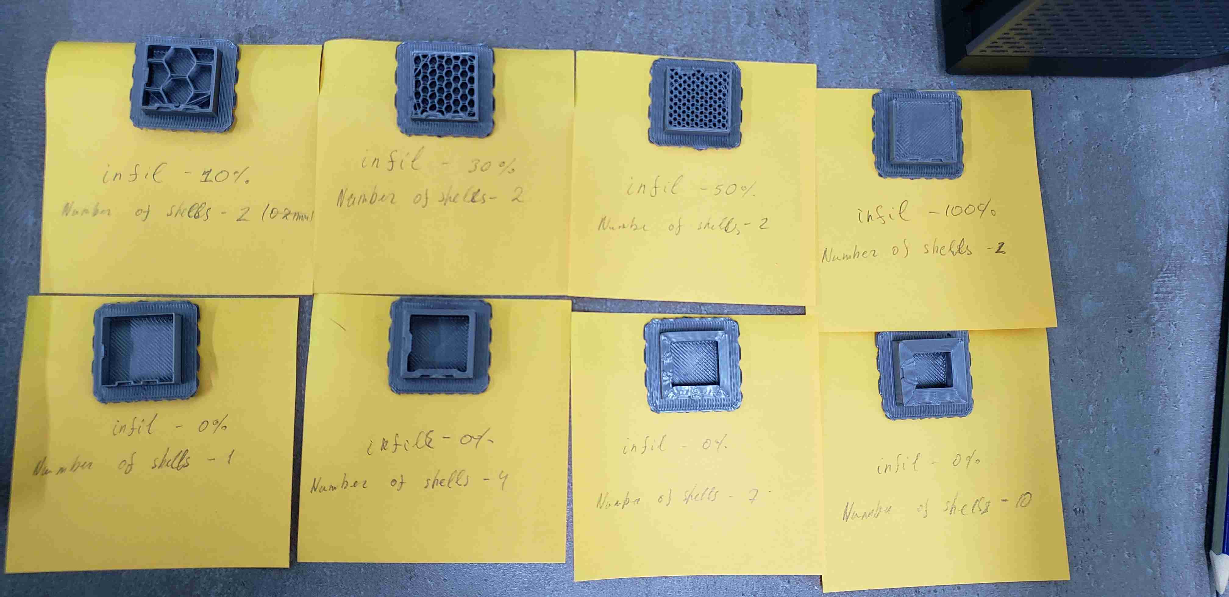
As you can find out from our group project page, we have tried to find out several parameters and different modes. So, to summarise the group project for me, I will tell what I learned by points.
- Toolchain to print a 3D object(file types, software, printer drivers, etc.)
- Differences between 3D printing materials
- Modes of 3D printer, support settings, filling settings
- Using a 3D printer, reading the manual
- Printing test files to find out clearance and design rules
Design and 3D print an object
After having done the first part of an assignment, I started to design. I took a look at Babken’s Fabacademy website. He printed a bearing. Then after discussing with Babken, we decided to make a 3D printer test for clearance and design it parametric. I used OpenScad. After having the design done, I uploaded it to thingiverse.com. Everyone can customize the design by changing variables.
Here is Thingiverse Link
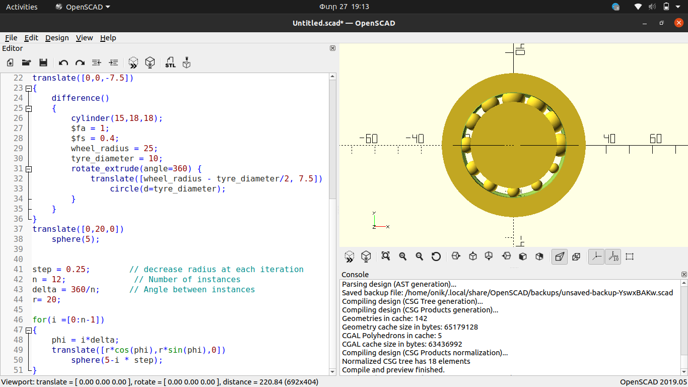
It is very difficult to tell how I designed it because Openscad does not have a tools or enhanced GUI, you just write code and it generates the design. But I will try to explain basic concepts. So, first tried to design the frame of bearing and for that I did this steps.
    difference()
    {
        cylinder(height,width,width,center = true);

        rotate_extrude(angle=360) {
            translate([wheel_radius,0,0])
                circle(r=tyre_r);
        }
    }
This part of code is placed in Module which should draw bearing.
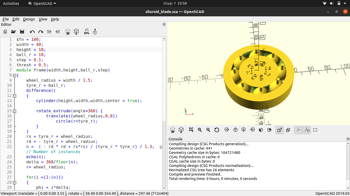
$fn = 100;
width = 40;
height = 18;
ball_r = 10;
step = 0.1;
thresh = 0.5;
module frame(width,height,ball_r,step)
{
    wheel_radius = width / 1.5;
    tyre_r = ball_r;
    difference()
    {
        cylinder(height,width,width,center = true);

        rotate_extrude(angle=360) {
            translate([wheel_radius,0,0])
                circle(r=tyre_r);
        }
    }
    // This part is calculating how many shperes can be placed depending on a given data like a width,height,ball_r and etc.
    rs = tyre_r + wheel_radius;
    rd = - tyre_r + wheel_radius;
    n =  ( - rd * rd + rs*rs) / (tyre_r * tyre_r) / 1.3;// Number of instances
    echo(n);
    delta = 360/floor(n);
    r= wheel_radius;

    for(i =[1:(n)])
    {
        phi = i*delta;
        //This part is placing spheres
        translate([r*cos(phi),r*sin(phi),0])
        {
            sphere(tyre_r - i * step - thresh);
        }
        // This is for little sticks on each sphere
        translate([r*cos(phi),r*sin(phi),tyre_r - thresh-3])
        {
            rotate(phi)
                cylinder(r = ball_r / 6,h = ball_r);
        }
        //this is just for debuging. It is printing data at console
        echo(tyre_r - i * step );
        // This part is for text. It is making number in front of each sphere.
        translate([(wheel_radius - 2*tyre_r)*cos(phi),(wheel_radius - 2*tyre_r)*sin(phi),height / 2])
            linear_extrude(2)
                rotate(phi)
                    scale([width / 100,width / 100,width / 100])
                        text(str(i*step));
    }
}

frame(width,height,ball_r,step,thresh);
Please pay attention to the comments in the code. I commented on which part of the code is for what. To be more clear, when you run only this part.
for(i =[1:(n)])
    {
        phi = i*delta;
        translate([r*cos(phi),r*sin(phi),0])
        {
            sphere(tyre_r - i * step - thresh);
        }
        translate([r*cos(phi),r*sin(phi),tyre_r - thresh-3])
        {
            rotate(phi)
                cylinder(r = ball_r / 6,h = ball_r);
        }
        echo(tyre_r - i * step );
        translate([(wheel_radius - 2*tyre_r)*cos(phi),(wheel_radius - 2*tyre_r)*sin(phi),height / 2])
            linear_extrude(2)
                rotate(phi)
                    scale([width / 100,width / 100,width / 100])
                        text(str(i*step));
    }
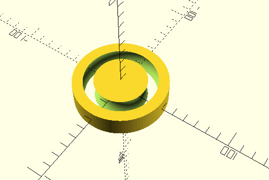
You will get this.
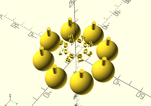
Final view of Design.

So, then I decided to upload my design to the thingiverse.com. The interesting part is that if someone wants download my design from thingiverse he can easily modify it by changing parameters. In the code placed parameters at the top and when I uploaded openscad file to thingiverse it automaticly detects parameters and their name.
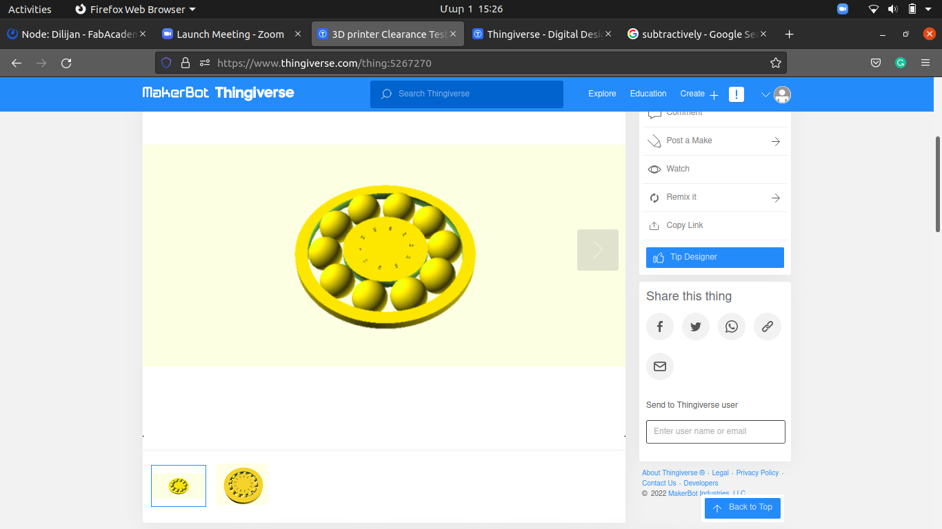
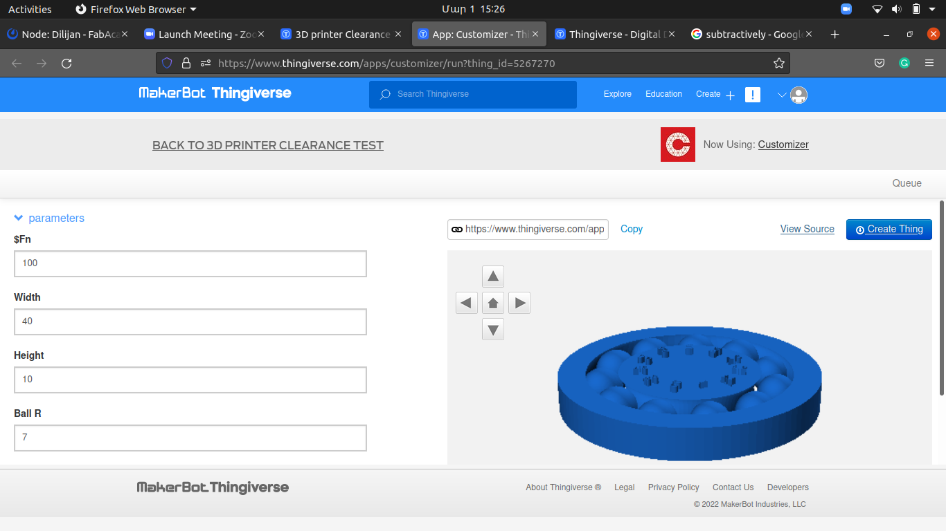

Here is the thingiverse link.
So, as the design was ready, I exported a .stl file from OpenScad and started the printing process.
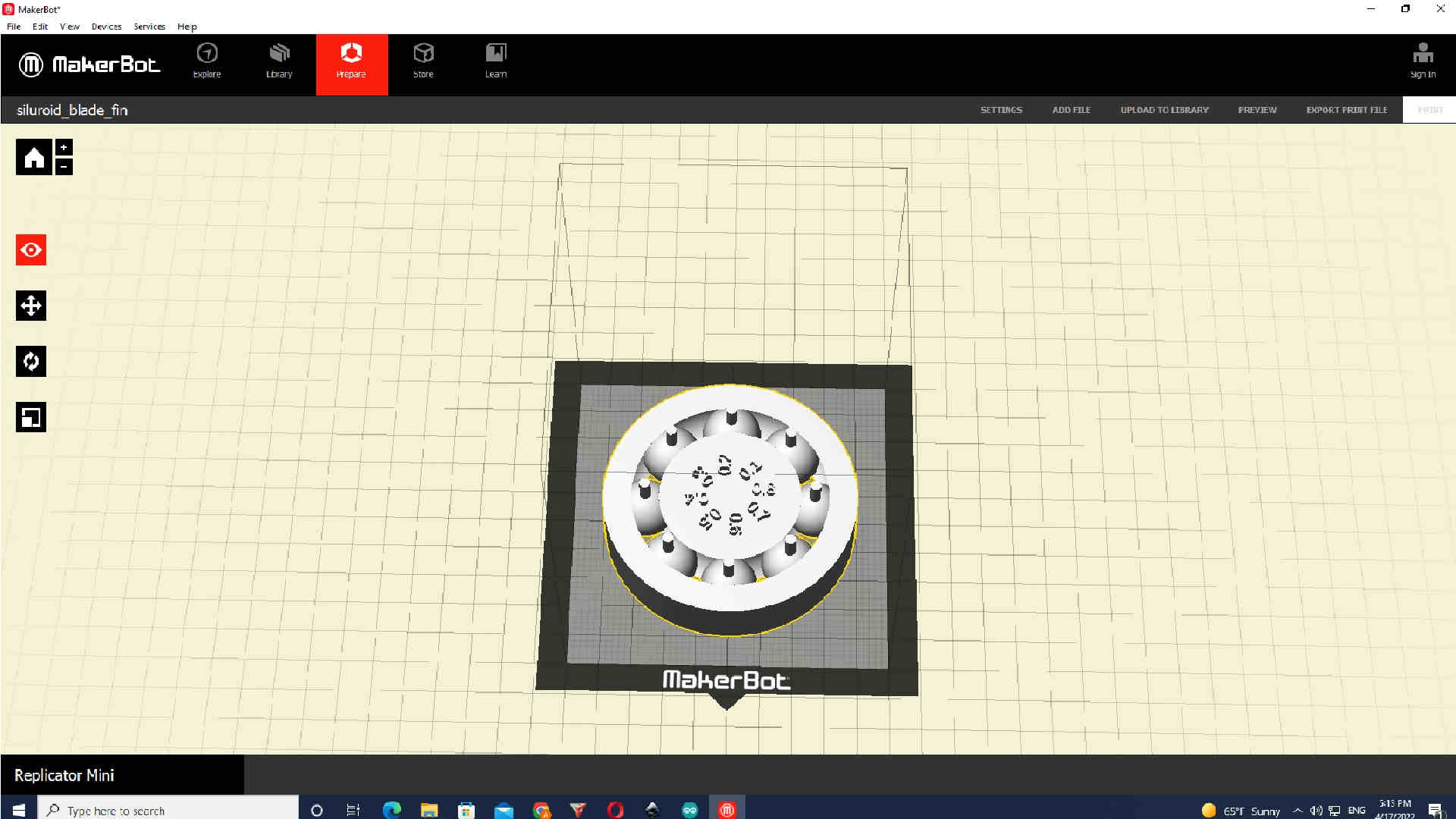
We have Makerbot replicator two in our Fablab. There was a problem because of little gaps and supports under the balls, but overall it was printed. It worked!
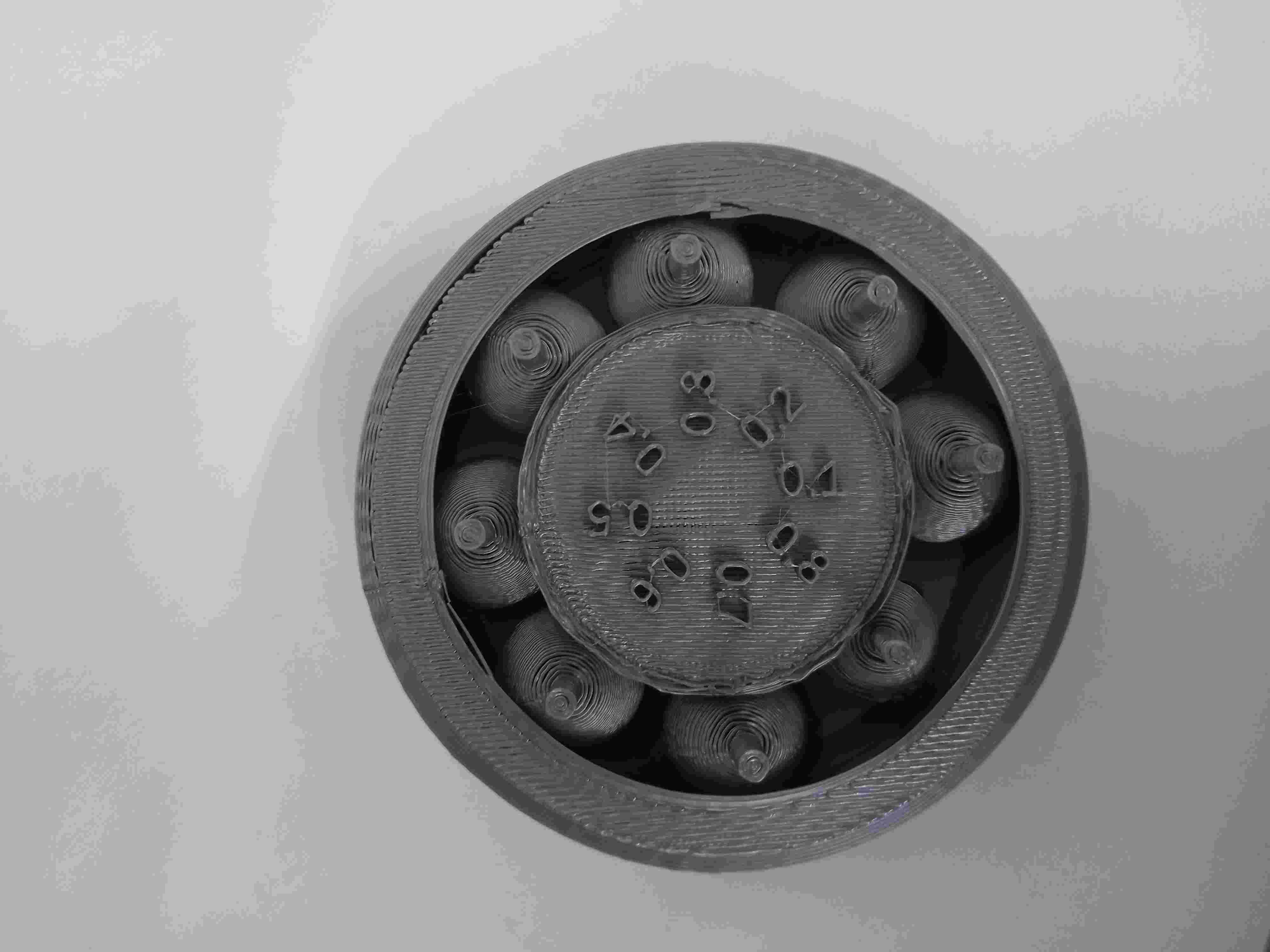
As you can see, there are lots of gaps, so after some research, I understood that the problem is 3D printer which is too old.
3D scanning
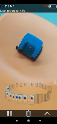
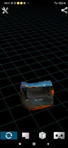
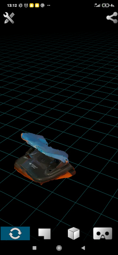
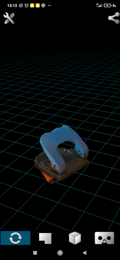
For this assignment, I tried different staff. But as we don’t have a special technology for 3D scanning, I decided to simply use my smartphone. So first, I installed 3D live scanner app from google play.


Then I just took the first item at my sight and ran the program, and started 3D scanning.
Conclusion
In the end, to sum up, this week, I learned how to 3D print your design and how to do 3D scanning. For me, 3D printing can be useful when you want to make something that can’t be made subtractively. But as a disadvantage, most of the 3D printers aren’t precise. Also, it could be life-changing to 3D scan by smartphone and 3D print it, but there is no app now in the market which can 3D scan an object with high resolution and precision. However, it is a matter of time. After a year or two, this problem will be solved.