10. Output devices
This week’s assignment is about output devices below you can see our group and individual assignments.
Group assignment.
measure the power consumption of an output device
Individual assignment.
add an output device to a microcontroller board you’ve designed, and program it to do something
Group Assignment
For the group assignment, we discussed different methods to calculate the power consumption of an output device and how to determine the best power source for your device. You can determine the power consumption of your output devices using several methods.
- Use a power supply to power up your devices and see how much current it consumes.
- Reading the datasheet of your device
Reading datasheet
For 16x2 LCD I found two datasheets related to this module. One is the datasheet of IC led driver that this module uses but the power consumption of this IC is not what I want to know as there are lots of other components on this LCD module. The next datasheet is from the Arduino website. It is specifications of 16x2 LCD. Below you can see a screenshot from the datasheet.

So, it says that maximum current consumption is 25mA.
Power Supply
Here you can see the video of measuring power consumption using power supply. It shows that the power consumption is approximately 20mA.
Output device
For, this week’s assignment I decided to design a new board which will be the first version of my final project’s PCB. My final project is an anemometer. It should calculate the speed of wind using a magnet glued to the wings and a hall effect sensor and show it on LCD and send it through RF to the PC. So, for this week I tried to design the first version of my PCB to find out some problems and to try to use LCD with it.
I interfaced 16x2 LCD with my board. I did some research about these LCDs. So, to control them you need 7 data pins as well as four other pins for enabling, read/write, register select, and contrast control.
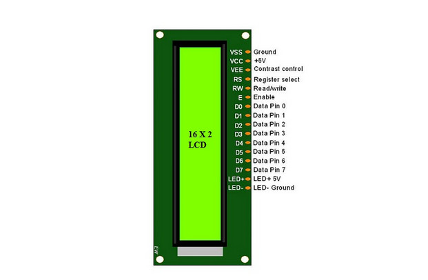
Below you can see pin dicription.

Features of LCD16x2
- The operating voltage of this LCD is 4.7V-5.3V
- It includes two rows where each row can produce 16-characters.
- The utilization of current is 1mA with no backlight
- Every character can be built with a 5×8 pixel box
- The alphanumeric LCDs alphabets & numbers
- Is display can work on two modes 4-bit & 8-bit
- These are obtainable in Blue & Green Backlight
- It displays a few custom generated characters
As you can see, to control this device you need a lot of pins from the microcontroller, so I decided to use an LCD controller that can be controlled by MCU using I2C pins. I2C is a communication protocol that is being used to transfer data from one unit to another one.

I2C
To learn about I2C I used this tutorial link.
The Inter-Integrated Circuit (I2C) Protocol is a protocol intended to allow multiple “peripheral” digital integrated circuits (“chips”) to communicate with one or more “controller” chips. Like the Serial Peripheral Interface (SPI), it is only intended for short-distance communications within a single device. Like Asynchronous Serial Interfaces (such as RS-232 or UARTs), it only requires two signal wires to exchange information.

Below you can see the I2C connection at the hardware level.
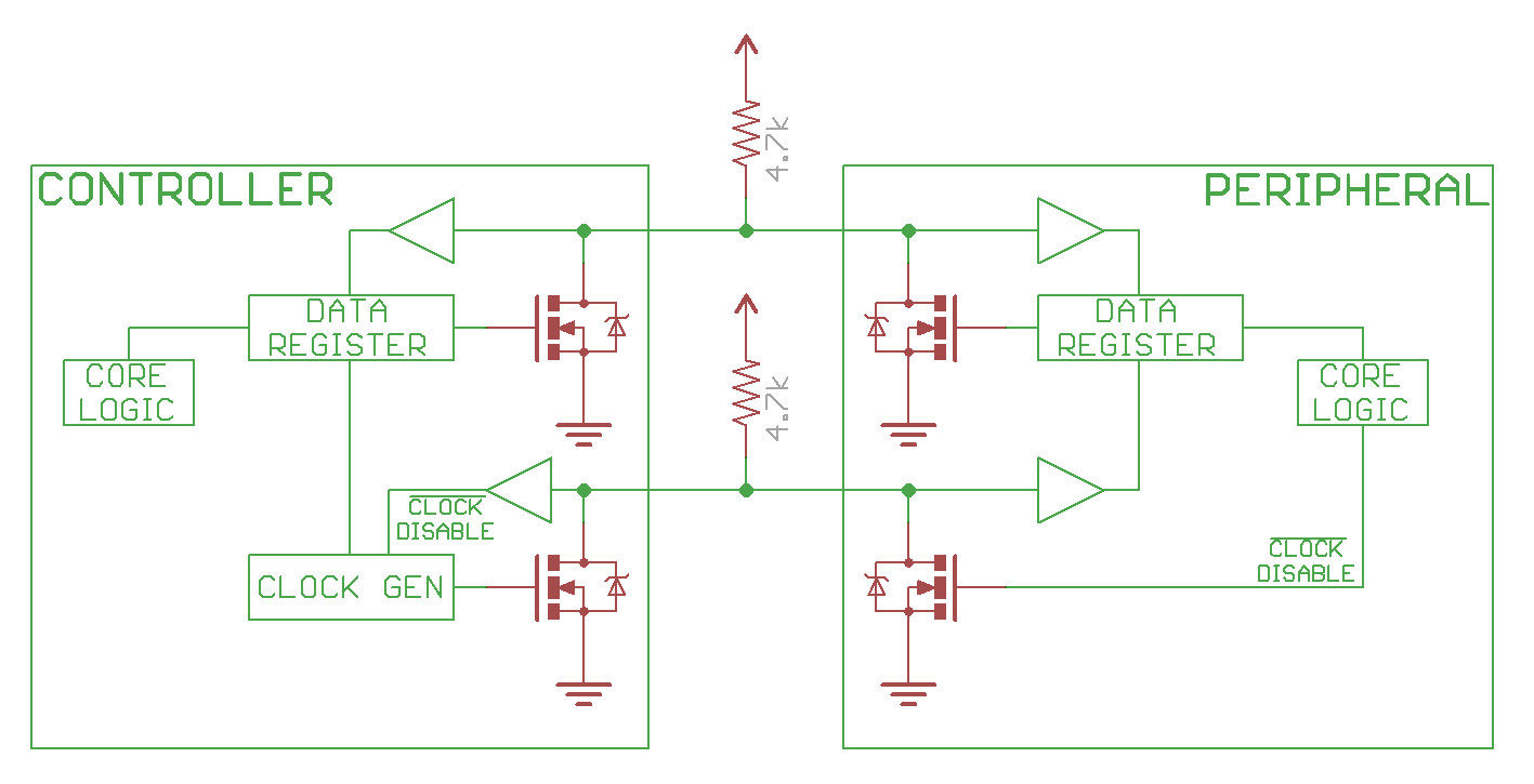
Resistor selection varies with devices on the bus, but a good rule of thumb is to start with a 4.7kΩ resistor and adjust down if necessary. I2C is a fairly robust protocol and can be used with short runs of wire (2-3m). For long runs or systems with lots of devices, smaller resistors are better.
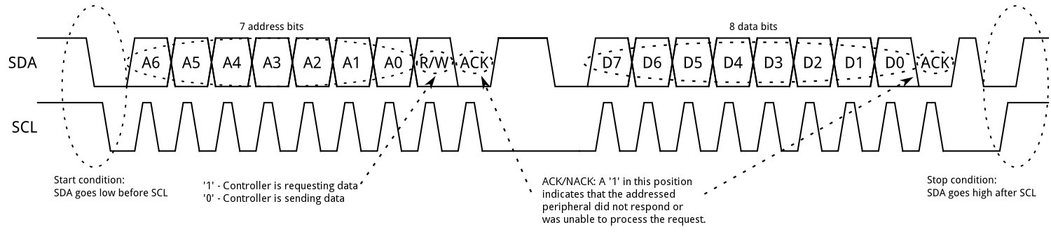
Each frame of data transmission consists of four parts.
- Start condition
- Address frame
- Data frame
- Stop Condition
So, to sum up, I2C is a good choice if you have one device that should control one or more devices. You don’t need a lot of pins only two SDA and SCL, you are going to use it for short distances.
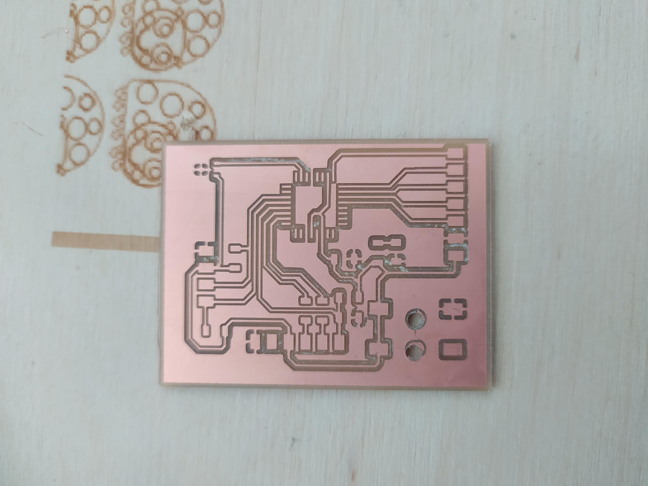
PCB Design And Milling
I tried to design a PCB for my final project so it is not only for controlling LCD. It has an onboard hall effect sensor A1324, an FTDI connector, and an SPI connector for RF. To control the same time LCD and RF, read data from the sensor and have an FTDI connector I need a lot of pins that’s why I chose Atmega328p for my MCU. Besides pins, Atmega328p is 5v tollerant and I don’t need an LDO to reduce voltage to 3.3V as I did for SAMD11C. Below you can see the schematic and layout designs of my board.
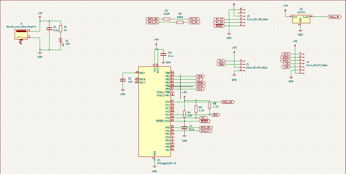
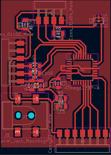
The most obvious problem with this design is the clearance between MCU pins that is less than the diameter of a 1/64th tool, but we have 0.1mm V bit in our Fablab and I planned to cut it with V bit, but I have got lots of problems with it.
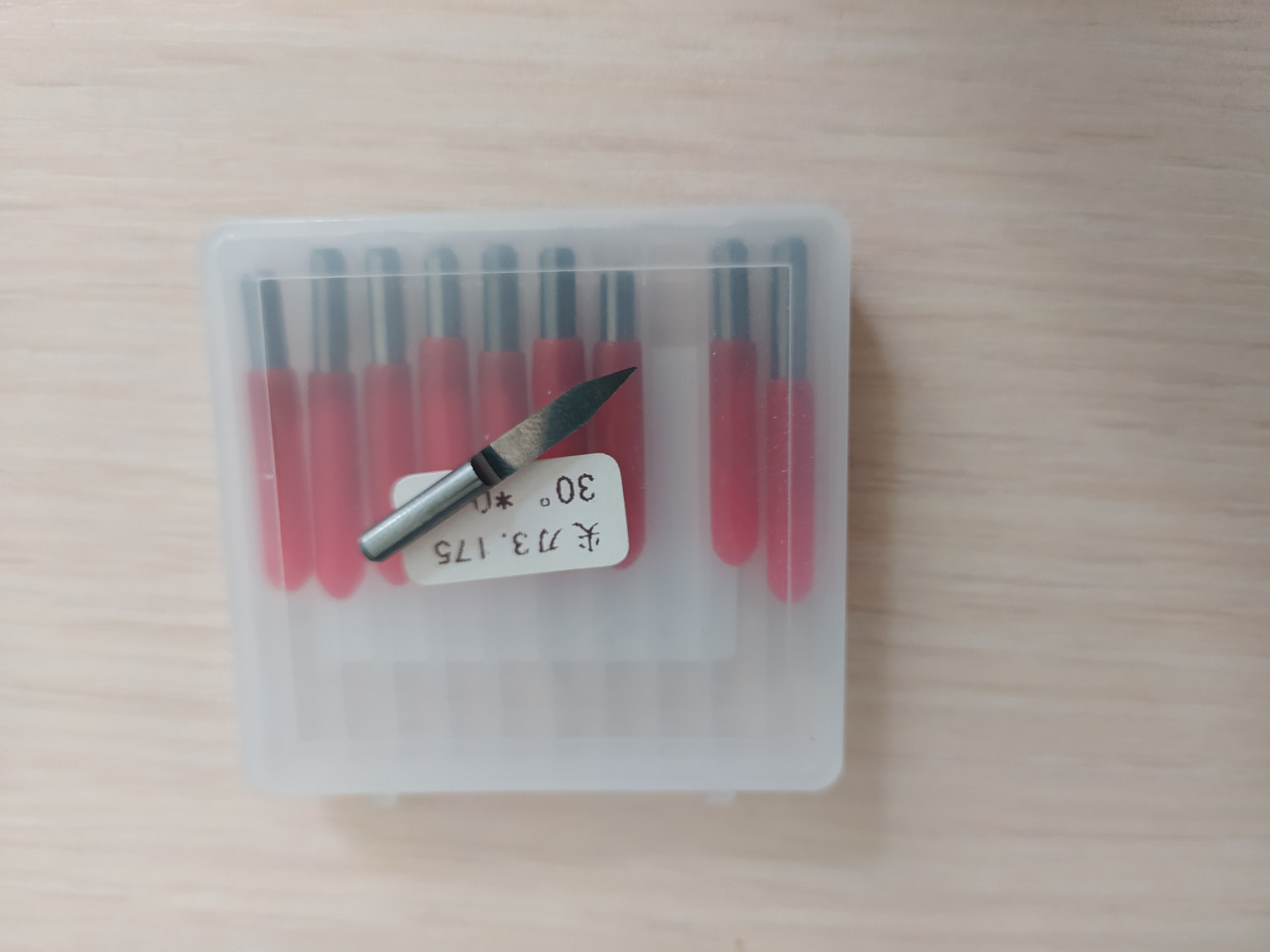
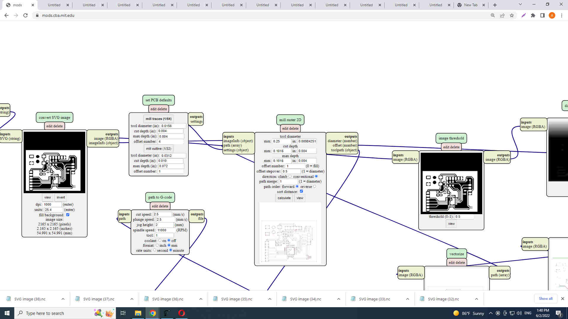
I needed to change tool diameter in Fab Mods and cut depth and max cut depth as well. I tried four times each time I was trying to change parameters to get the desired result but I failed.
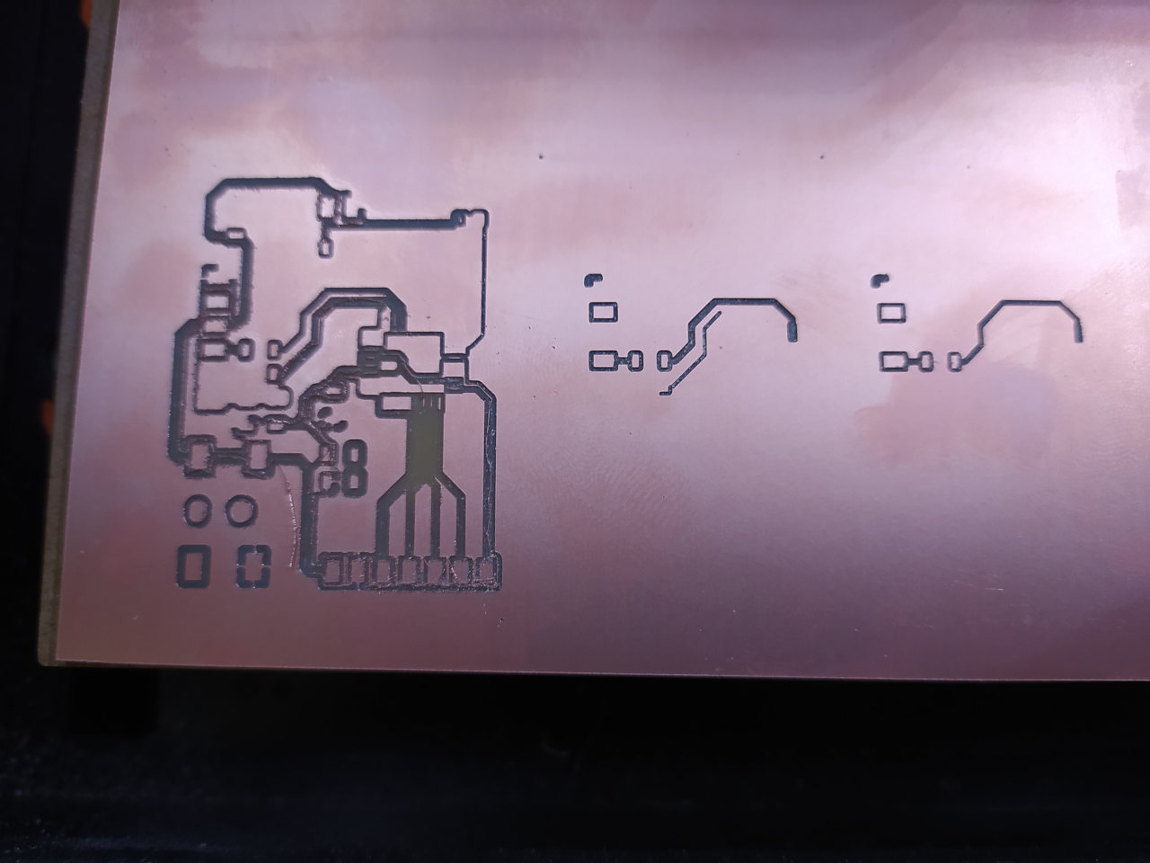

The problem was the cut depth, as my bed for PCB was not ideal and the tool diameter of V bit changes proportionally to the cut depth it was really hard to set zero level for the z-axis. So, having numerous fails I decided to use the 1/64th which equals 0.397 mm. The space between the pins of the microcontroller is approximately 0.25mm, so I am using 1/64th I will lose 0.12 mm of the thickness of my pins and tracks but as the tickness was set to 0.5mm I thought that it is ok to have a bit less, 0.38 mm tracks. I used the 1/64th tool but to make fab mods generate g-code I told it that I will use the 0.25mm tool.
And, finally, I succeed. SRM-20 milled it as it used to, nothing special and the result was great.
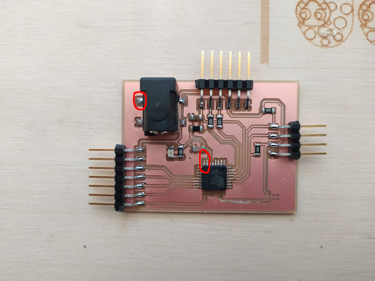
The drills for the power jack connector I did by myself and assembled it.

At this point, I did several checks. I checked shorts using a tester and connections of MCU pins and etc. Then connected it to the power supply and found problems.
- I mixed pins of the power jack connector and didn’t connect the jack’s ground pin to the PCB ground.
- I forgot about 16 Mhz XTAL for my MCU
I took note to change the design for the final project but at this time I am going to power it up from the FTDI connector. I powered it from Arduino and found that because I don’t have an XTAL I can’t program MCU. I did some research and find out that I can change fuse bits of MCU using some source of 16Mhz clock and after changing fuse bits I can use it without XTAL. So, I took the signal generator and configured it to generate a signal with these parameters Vpp = 5V Vofst = 2.5V Freq = 16Mhz.

I used this tutorial to program my Arduino as an ISP programmer and use AVRDUDE to program the fuse bit of my Atmega328p to work with an internal 8Mhz clock. Also, I learned how to add a board to my Arduino boards to program my board in Arduino IDE using Arduino UNO as a programmer. First, I set up Arduino Uno and my board and connected it to my computer.
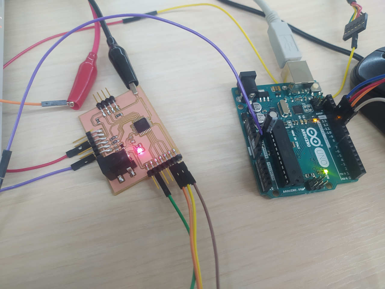
As you can notice from the image, there is a capacitor connecting Arduino’s RESET pin to the ground. I need this capacitor only when I am using AVRDUDE directly from terminal. This capacitor is needed to configure reset timing during the programming, but if you are programming using Arduino IDE you don’t need this capacitor. So, before having ready my toolchain I did several steps.
- Open Arduino IDE, choose Arduino UNO as a board and choose a serial port for it.
- Open example scatch called ArduinoISP from examples
- Upload it to your Arduino.
- Connect Signal Generator output to the XTAL1 pin of your MCU.
- Place 10uF capacitor between RESET and GND of your Arduino UNO
- Open a terminal and run this command
avrdude -c arduino -p m328p -P /dev/ttyACM0 -b 19200 -U lfuse:w:0xe2:m. Now I programmed fuse bits to use the internal 8Mhz clock.
At this point, I had my MCU ready for programming. Now I need to add a board to the list of Arduino Boards to program it from Arduino IDE.
- Open the root directory of Arduino mine is this ~/Downloads/arduino-1.8.19-linux64/arduino-1.8.19.
- Go to the ~/Downloads/arduino-1.8.19-linux64/arduino-1.8.19/hardware/arduino/avr/variants folder and add a new folder named “Atmega328p”.
- Now go to ~/Downloads/arduino-1.8.19-linux64/arduino-1.8.19/hardware/arduino/avr/variants/standard and copy the file “pins_arduino” and paste it in the location ~/Downloads/arduino-1.8.19-linux64/arduino-1.8.19/hardware/arduino/avr/variants/Atmega328p
- Go to the location ~/Downloads/arduino-1.8.19-linux64/arduino-1.8.19/hardware/arduino/avr. There is a text file with the name “boards.txt”, open it to edit.
Scroll down to the end of the codes and add these few lines:
##############################################################<br>
ATmega328p-8.name=ATmega328p-Internal 8Mhz
ATmega328p-8.upload.tool=avrdude
ATmega328p-8.build.mcu=atmega328p
ATmega328p-8.build.f_cpu=8000000L
ATmega328p-8.build.core=arduino:arduino
ATmega328p-8.build.variant=ATmega328p
ATmega328p-8.upload.maximum_size=32000

##############################################################
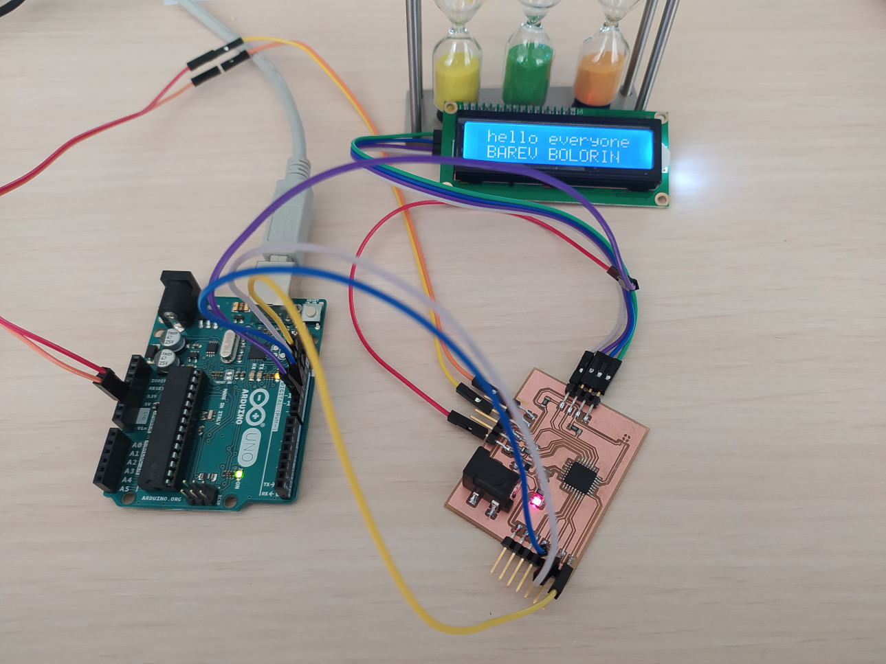
That’s it. I know that there are many steps, but in this way, I have a PCB with atmega328p without using XTAL clock and without capacitors that the clock needs, so it reduces the BOM of material for my board. At this point I downloaded LiquidCrystal_I2C lib from Arduino library manager and uploaded a test program to write “hello world” on lcd.


By the way “BAREV BOLORIN” means in Armenian hello everyone.
Hero Shot
HERO SHOT OF MY BOARD!