7. Computer-Controlled Machining
This week our assignment was to make something big. It was hard to determine what to make. But I noticed that we have a table in our lab that shakes because of bad legs. So, I decided to make new legs to make the table stable.
Our assignment for this week is
Group assignment.
- Complete your lab’s safety training
- Test runout, alignment, speeds, feeds, and toolpaths for your machine
- Document your work to the group work page and reflect on your page what you learned
Individual assignment.
- Make (design+mill+assemble) something big
Group Assignment
For the group assignment, we did safety training on how to use equipment, how to choose true feed rates, spindle speeds, and other settings for different materials. Also, we discussed different tools and their usage.
Table leg design
As I already mentioned, I wanted to make our table stable and decided to make new legs. Below you can see a video of a shaking table.
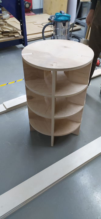
So, I wanted to skrew out table legs and make new ones. I designed two legs as it was but in a way that each leg would have space for some staff. I used Freecad, it was a bit hard, but to be honest it is a matter of time to get familiar with Freecad.
Below you can see the design.
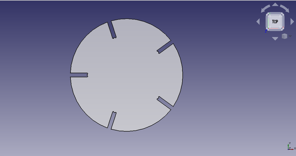
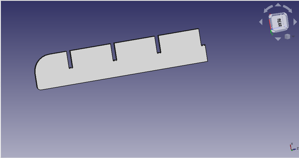
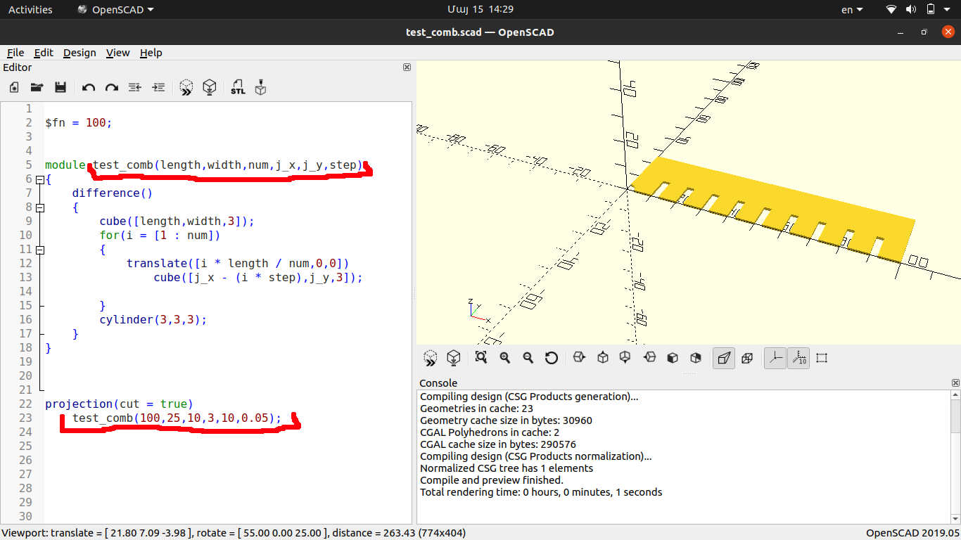
This design is parametric, so for example when I started cutting, first of all, I cut a test comb to determine the true sizes of joints for a given material. Below you can see a list of parameters.
| Name | Value | Description |
|---|---|---|
| joint x | 75 | Length of Joint |
| joint y | 17.2 | Width of Joint |
| joint gap | 150 | Gap between joints |
| joint # | 4 | Number of Joints |
| Leg Y | 770 | Leg width |
| Leg X | 150 | Leg length |
| Leg # | 5 | Number of legs |
| Radius | 100 | Radius of base segment |
| Dogbone R | 3.1 | Radius of Dogbones |

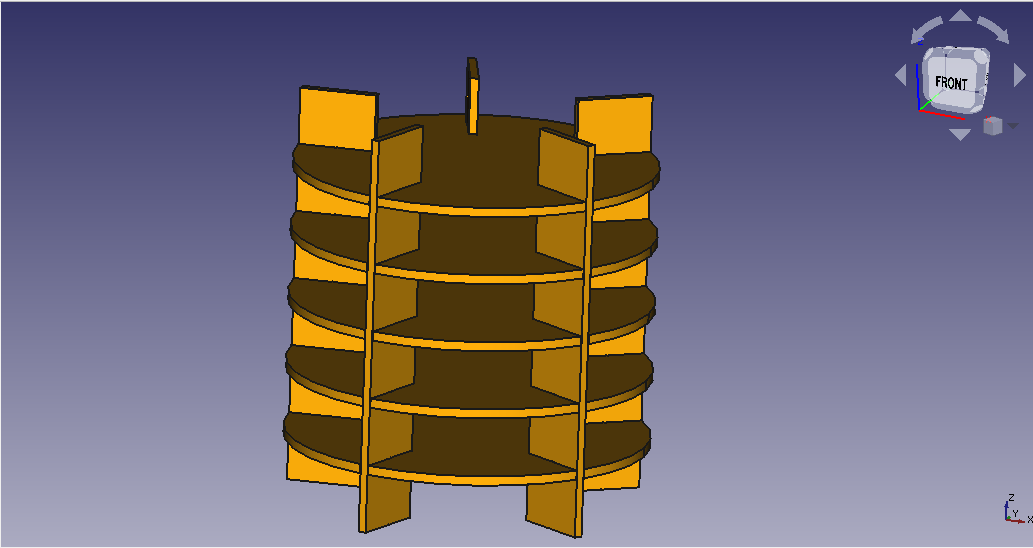
I am going to make five of each and then assemble all together to have a leg. Something like this.
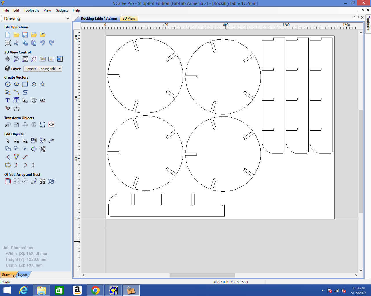
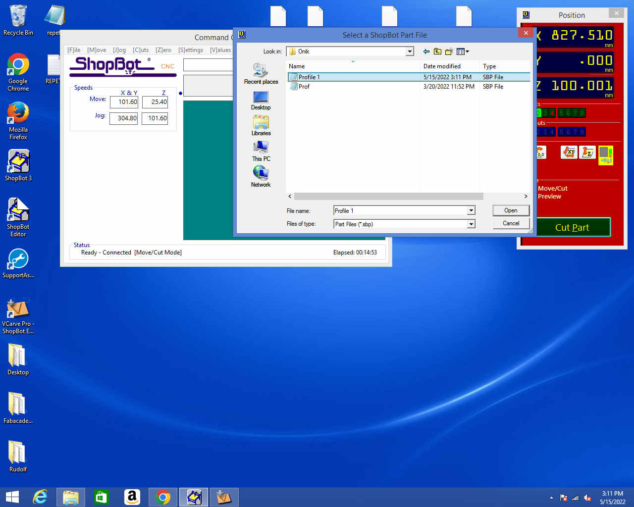
Having done the design I exported .dxf files to import them in V carve, a programm which generates a G-code. To export a .dxf I need to place my part on the XY plane and then from files choose export .dxf.


Having .dxf files now I need to generate toolpathes and fix the material on shopbot and start cutting. But before cutting the main design I cut a test comb from the material that will be used to correct joints. I used the test comb design that I designed in week3. It was parametric so I just changed some values for new material and exported a .dxf file.
Then I fixed piese of a material from which I was going to cut my design and cut the test comb.
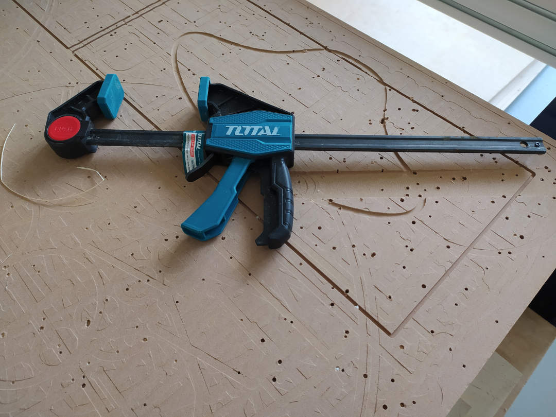
I used clamps to fix material on the bed.
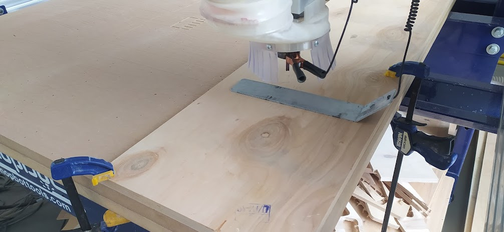
In this picture, you can see the material fixed and a process of taking zero of the z-axis.

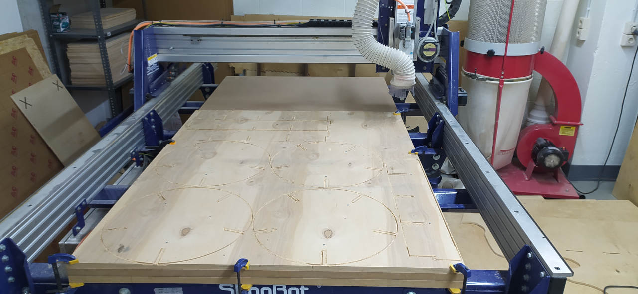
After some test and changing values of parameters I fixed big piece of material and finally started to cut.
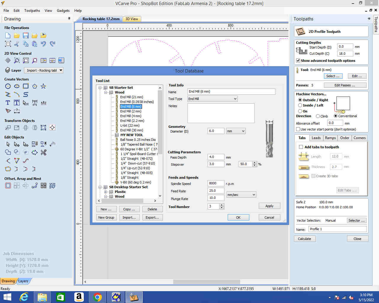
In this pictures you can see toolpath generation process.


So, having all set I started to cut but after first pass of shopbot I understood that I need to fix the parts that will be cut to be sure that they will not move on the last pass. I decided to use fasteners to be sure.

Below you can see the Hero Shot of something big and of course a table that is already stable.
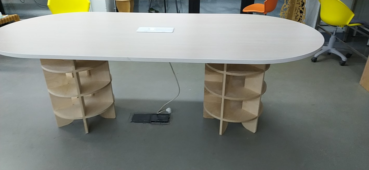