4. Computer controlled cutting
Group Assignment
This week we had a group and a personal assignment. For group assignment we had to: 1. Characterize our fab lab’s laser cutting machine and 2. define the power, speed, kerf and press fit for a given material. 3. Characterize our lab’s vinyl cutting machine 4. Define the best force/speed in the vinyl machine to have a nice cut.
Link to the group assignment: here
Laser Cutting machine
Main learnings from the process
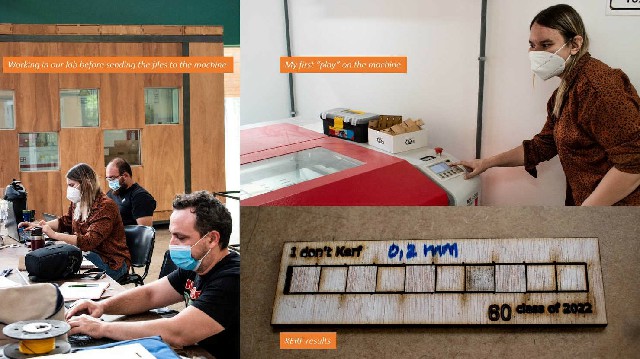
I am surprised about how quick I learned about using the laser cutting machine, and also how many things happened during the process that made me learn even more. Basicly, I will summarize the main recommendations below:
- Make a workflow or guidance containing all the steps to run the machine, you can even make a checklist with them.
- Practice, practice, practice. Even if is not your work cutting, just be there with your classmate whenever you can
- Test all your files (dxf version, scale, overlapping lines)
-
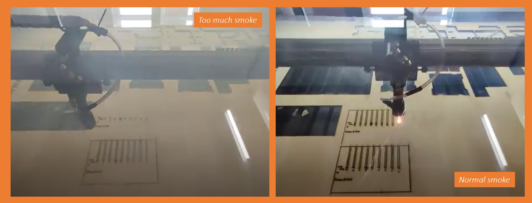
Be aware of the amount of smoke you smell and see inside the machine. The following images show a good and a bad situation (I told we experimented a lot of things, including not properly plug the vent extractor in
 )
)
-
Be sure your material inside the machine is not bent (another experience
 )
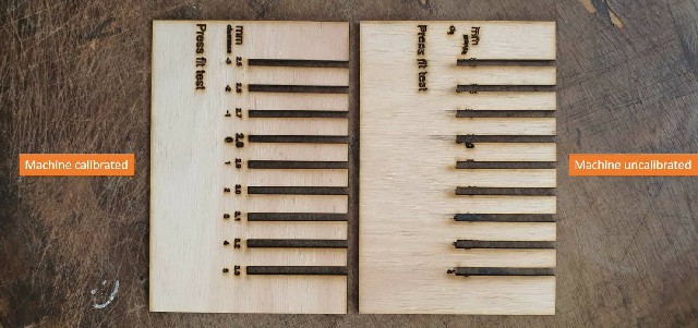
) - If you see your machine is doing weird things like the images below, check it and learn what have happened. (We unintentionally uncalibrate the machine
 , most important, now we know how to fix it haha)
We experimented a lot of things, we did it acompanied by someone who has experience using the machine but without the main local instructor, so our conclusion is try not to use the machine by yourself because the machine senses it!! haha 
Material and thickness: 3mm Plywood
Determining power and speed
By doing this test we wanted to know which speed and power do we need to cleanly cut a 3mm plywood piece using our machine. Remember, this always will depend on: the machine, the material and the thickness. Every time you change one of these variables, you need to do this test.
Steps 
- Design a simple file containing little shapes in a “table” with columns of speed and rows of power
- Load the file to “power cut” software and apply different colors to each shape so we can have different “layers”
- Assign power and speed to each “layer” following the indications in the coincident row and column (speed and power) Also select “cut” or “engrave” in the specifications, All these will be “cut” even though we have labels to engrave. It is so because, in this case, we don’t have shapes to “fill in” or “paint” we just want them to be visible marked on the plywood. Use engrave only when you intentionally want to “draw/paint” something. To “visible mark” your labels on the material use “cut” with 10 power, 80 speed.
- put layers in order depending on having or not labels to engrave. The last thing to cut here will be an external square to separate the piece of the original material.
- Simulate the path of the laser in the software
- Upload the file into the machine and start!
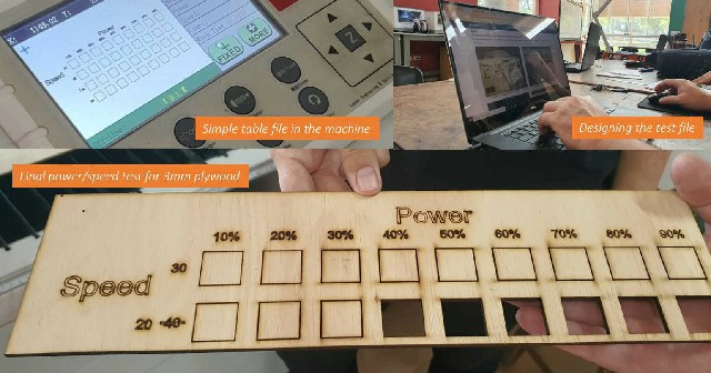
Results: To cleanly cut a piece in a 3mm plywood speed is 20 and power is 40
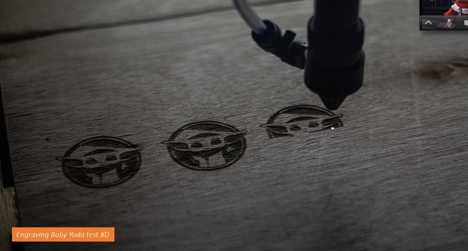
We also enjoyed engraving some Baby Yodas testing differents speeds and powers
Determining KERF
Every time a laser passes along a given material it “burns” part of it. We need to take this into consideration when designing anything we want to cut because if we, let’s say, want a piece with 5mmx5mm area, if we draw as it is at the end we’ll have a smaller piece than we wanted. The amount of material the machine will burn for a 3mm plywood is the purpose of this test. Once again, do this every time you need to change your machine, material or thickness
Steps
- Design a simple file with 10 squares with 10mm each placed in a row forming a shape like this (add photo)
- Assign a color for the vertical lines inside the rectangle and another one to the outside rectangle, and the last one will be for the boundary of the entire piece (so we can extract our work from the rest of the plywood)
- Load the file to power cut and apply 20 speed and 40 of power to all layers
- Put the vertical lines layer first, and the rectangle containing them after and the boundary rectangle last
- Start cutting
- Remove the material from the machine, also the little squares fallen
- place all the squares inside the empty rectangle
- measure the little empty part inside the rectangle using a calibrator
- divide this by 11
- You’ll have your KERF!!
Warnings!
- Ensure your file has not overlapping lines before sending it to power cut software
- The machine just “reads” vectors
- All “text” should be converted to “curves”
Results: the calibrator showed 2,2mm. Dividing by 11 the result was: 0,2. KERF=0.2 for a 3mm plywood
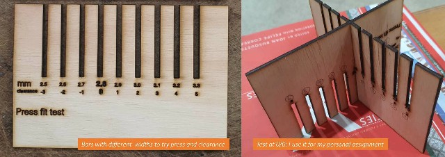
Press fit test
We do this to know the “clearance” of a given material when pieces of it join each other. The level of strength or smoothness between each piece will depend on the function they’ll have on our design (for instance, it could be a strong structural fit or a loose one to have a hinge). We call this “clearance” and it also varies with the machine, thickness and material. So do this test every time you change any of them.
Steps
- Design 1 simple shape like this below we call it a “hair comb”
- Each empty long rectangle needs to have a different width starting with 0 in the center.
- Then add 0.1 mm each to the right and subtract 0.1 each to the left. 3 to the left and 5 to the right would be enough
- Add labels showing the width of each empty rectangle in mm and also name each with a number
- Copy and paste the shape so you have 2 identical to cut
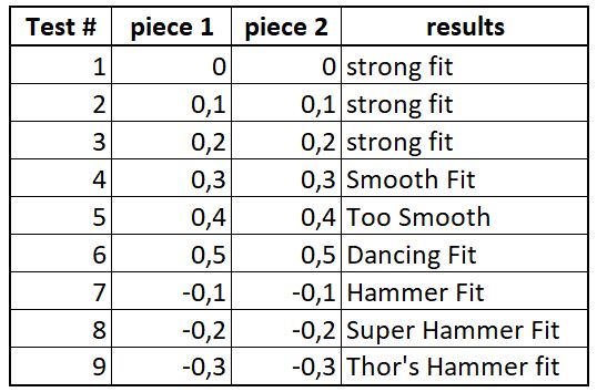
- try combining each number among themselves and feel how easy or difficult it is to join them. Write your results in a table like this to show your results
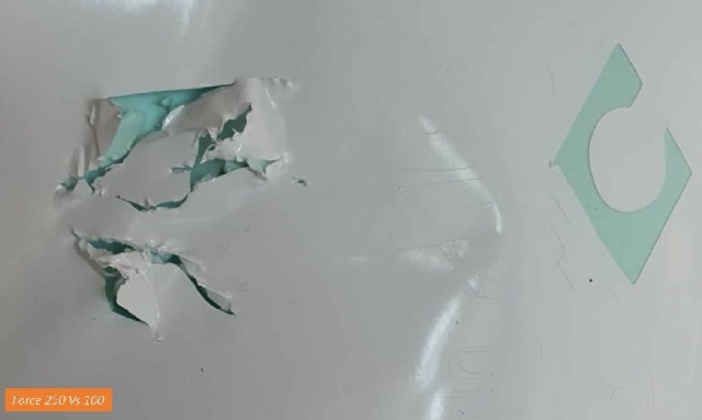
Vynyl cutting
The main goal here was to determine a clean and smooth cut using vynil. First we try (by mistake) use the force in 250  , then we change it to 100, and it seems to be ok but then when I used it with my project I realized we needed to try a little more force, so all my classmates used 130 of force and it was perfect! by doing this we now know that this specifications should be used whenever using vynil in the same conditions of humidity and temperature of that day haha (25°C, 30% humidity aproximately)
Personal Assignment
The personal assignment for this week was to build a press fit construction kit from a parametric design and a vynil cutting product
Press fit construction kit
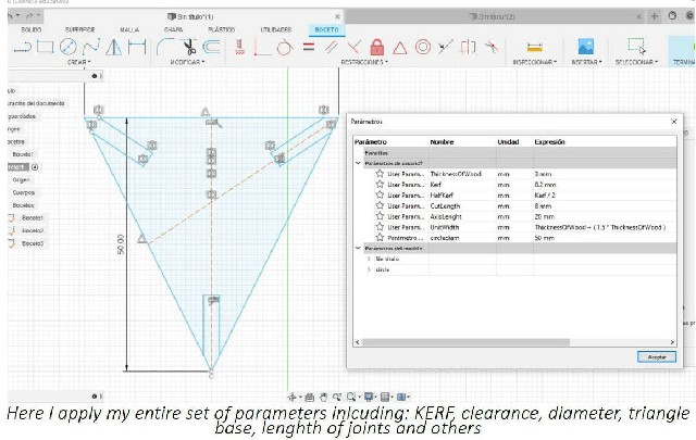
First I thought about do something more connected to my final project, may be a structural waffle design in otder to use it as a formwork with a fiber glass skin. Finally, because lack of time and some technical issues I just decided to so this assignment to: 1. learn parametric design better (which I thought I understood but I realized that at that time I needed to get it better) 2. Better understand the differences in kerf and clearance and how does them feel in the material.
For my personal assignment I decided to use the same materials as the testing; 3mm Plywood
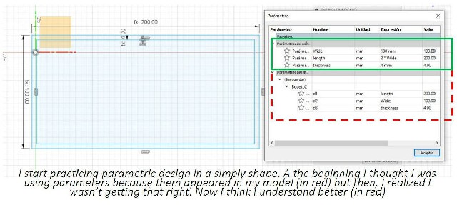
First I started to understand parametric design better
Then, by doing projections of the bodies in fusion, I create piece by piece my kit and save each one as a dxf file and joined all pieces together in a common canvas in inkscape.
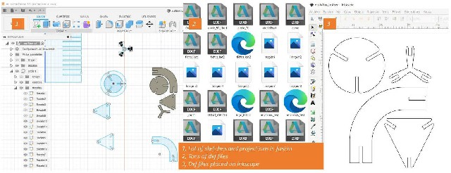
Then, by helping a classmate, I learned how to do all of this directly from fusion using the “drawing” environment.
So the main lesson here is: do help your classmates because you'll learn lots in the process
I did all my work with the machine uncalibrated (all my classmates learned thanks to my mistake haha)
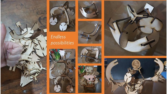
If you see closely you’ll be notice the “imperfections”. Because lack of time I decided to not do the entire construction kit again, but I helped the others with theirs so I can guarantee the lesson is learned 
The idea of my construction kit is to discover new shapes from the most used figures. I had a lot of fun discoverying them!
Vynil cutting
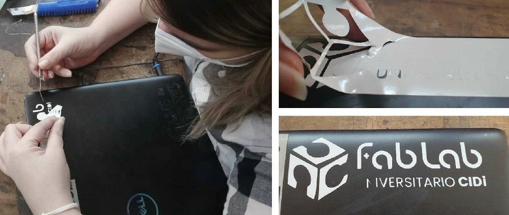
For this part of the assignment I decided, once again, to be conservative and just try make the fab lab logo for stick it on my computer. For this, I use 100 of force and realized that I needed to add a little more: 130 would be ok and my classmates proved that.
First I vectorized the logo, then turned it into lines, and saved it as SVG, load into the machine and cut it.
After that I removed the back of the vynil so I could paste all the “rectangle” where the logo was cointained and sitck it to my laptop, the last thing I did was to remove all the “waste” and the logo was visible! but I wasn’t perfect.
Files
Individual assignment:
Group Assignment: - Kerf testing: Link - Pressfit test: Link - engraving test file: Link