8. Computer controlled machining
This week we had a group and an individual assignment as follows:
-
Group Assignment Do your lab’s safety training test runout, alignment, fixturing, speeds, feeds, materials, and toolpaths for your machine
-
Individual Assignment Make (design+mill+assemble) something big (~meter-scale)
Group Assignment
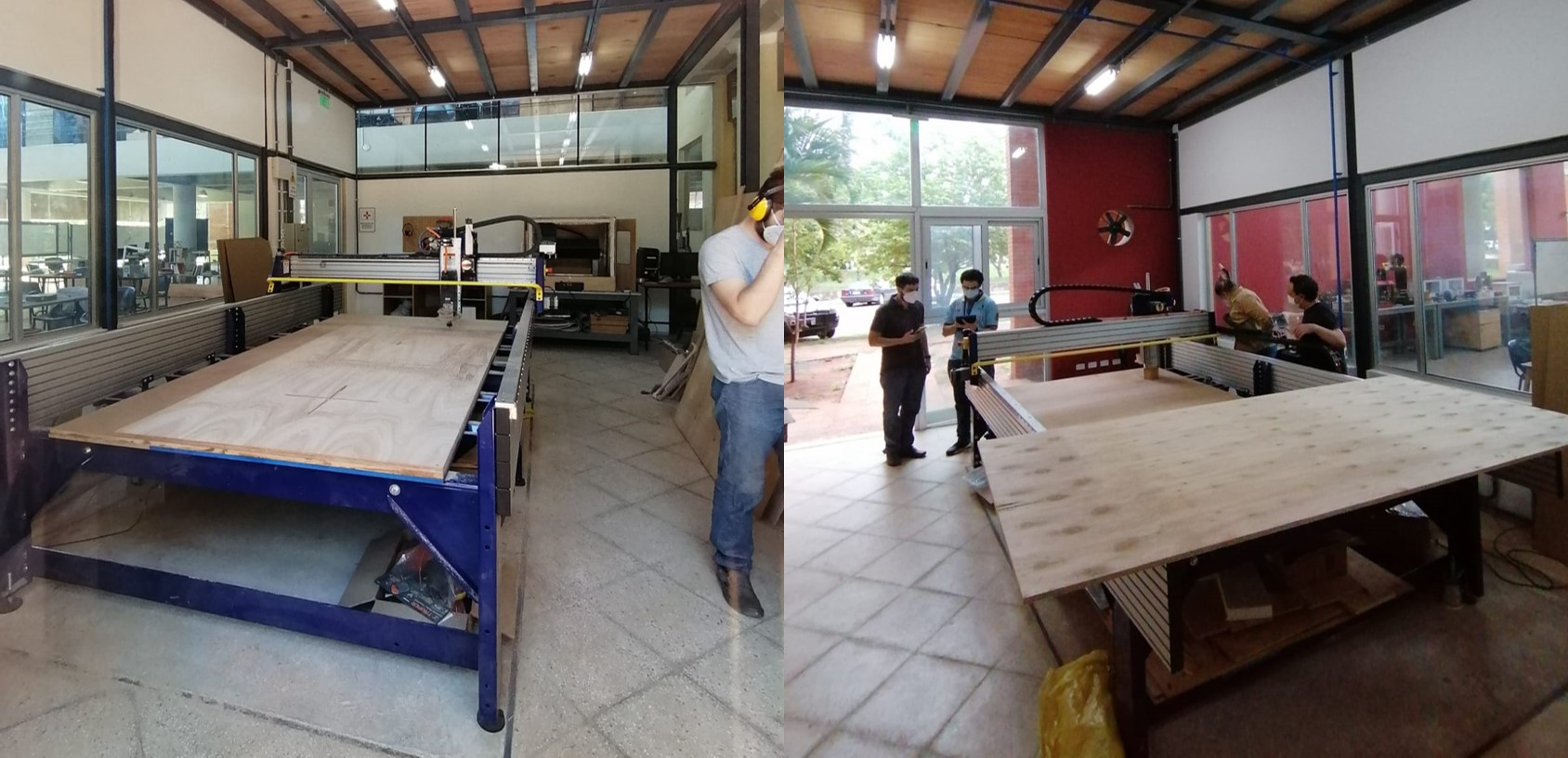
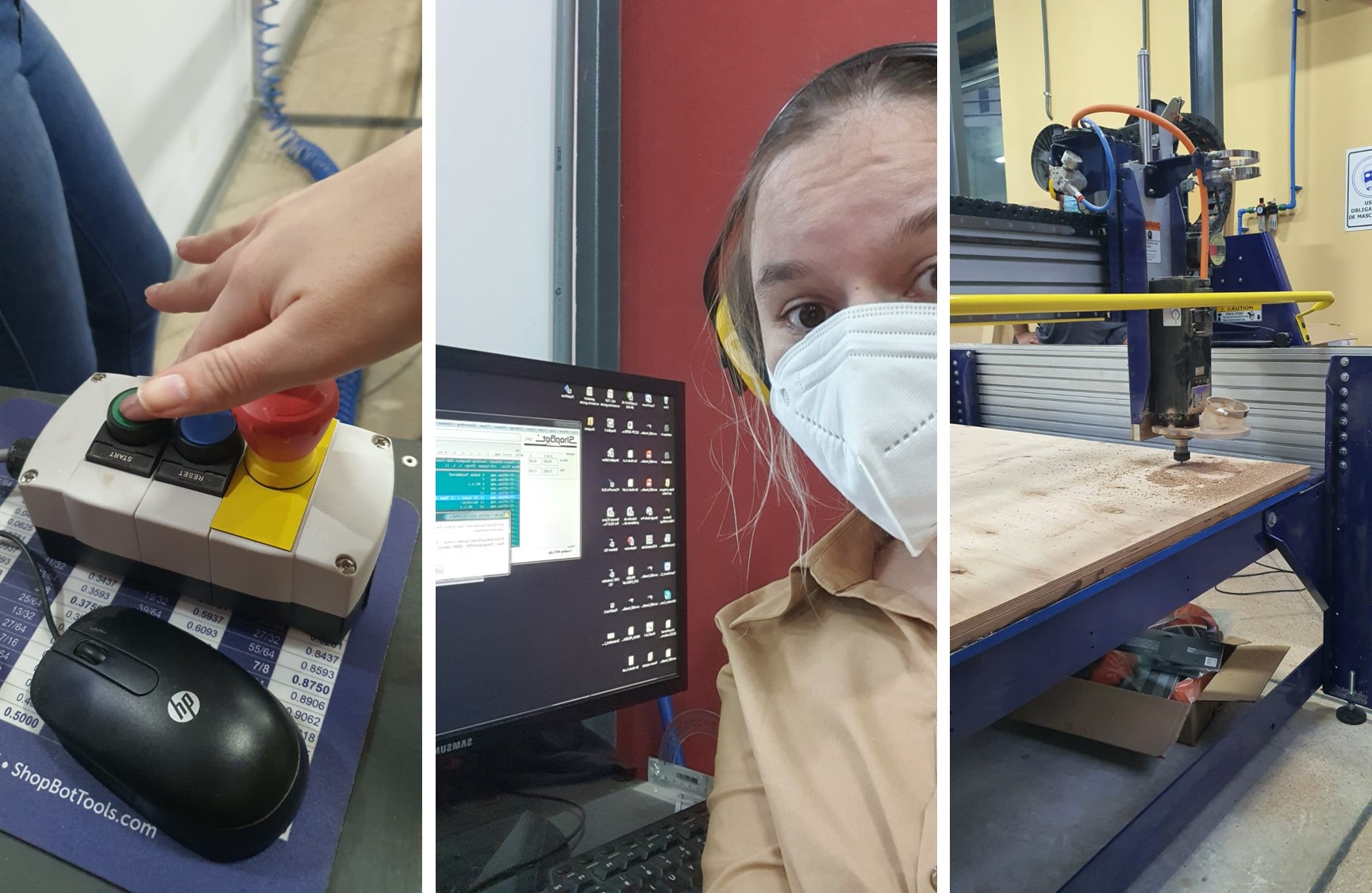
We did a safety training and learned how to operate the milling machine (a beautiful and massive shopbot)
The extensive safety rules and steps we followed can be found here
The main steps in order to use the shopbot are:
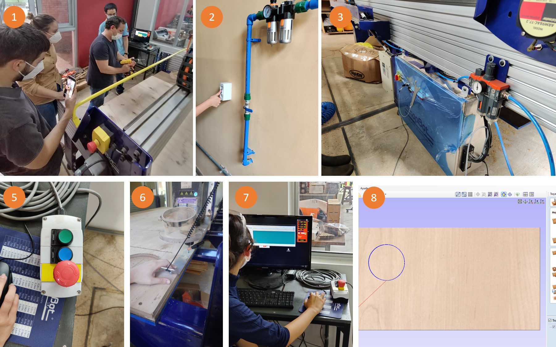
in order to use the shopbot are: - Set your stock to the work bed using screws
- Turn on the compressor
- Set your end mill (with the machine red button turned off)
- Turn on the machine
- Open shopbot3 and press reset button
- Set Z origin using the magnetic sensor
- Set XY origin
- Open and configurate your work using Vcarve pro, pre view it and simulate it before saving
- Open shopbot3 and press cur part, select your file
- press start button, then ok
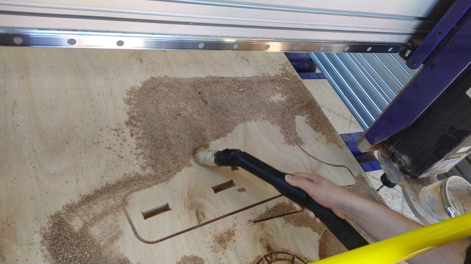
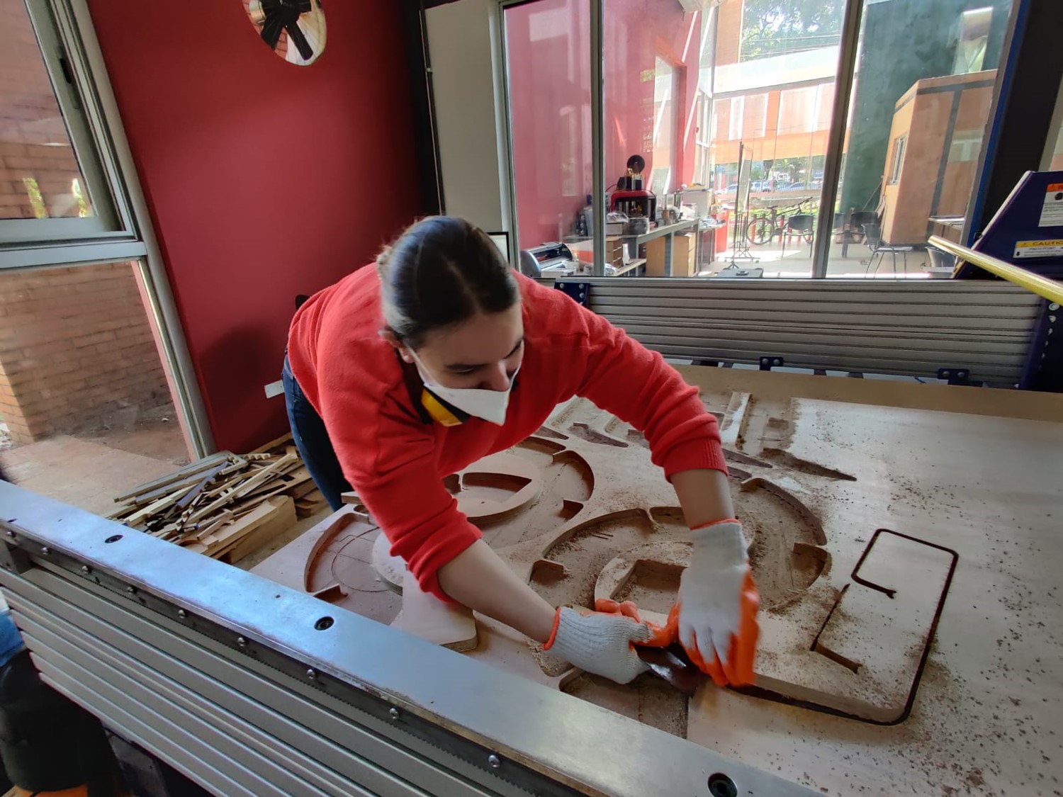
Pay attention to your machining work until it’s done. then remove your pieces using gloves. Finally remove the remainging stock and clean the area
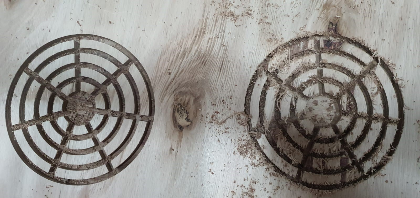
In order to determine the best speed, feed, end mill and work trajectory we did some tests, at the end the final results for 18mm plywood were:
- SPEED: 6.000 mm/min
- RPM: 10.000
- End mill: 1/4 (6.721 mm) with 2 flutes
- Trajectory: conventional, down cut
- Offset: depending on your design
- FEED: 0,1 mm
Safety Rules and machine Testing = DONE
Individual Assignment
Make (design+mill+assemble) something big (~meter-scale)
1. Design
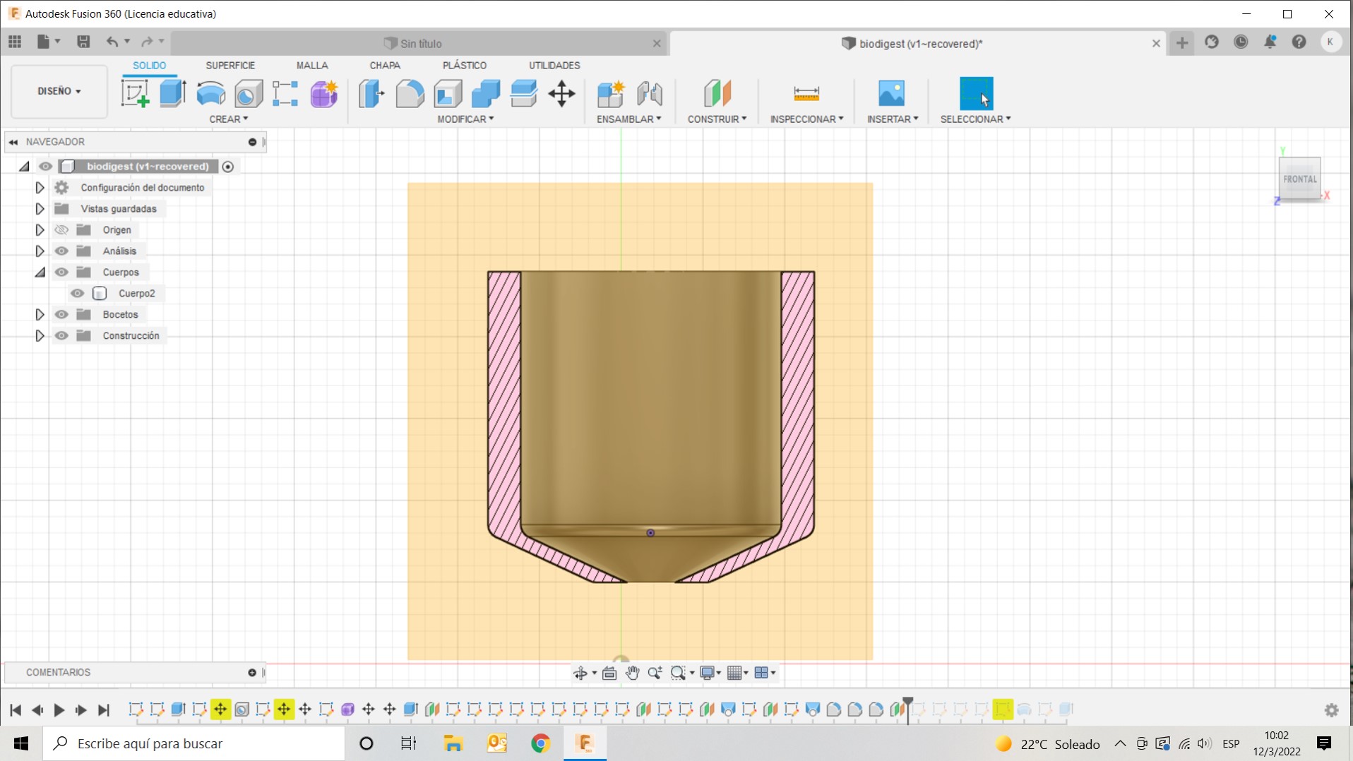
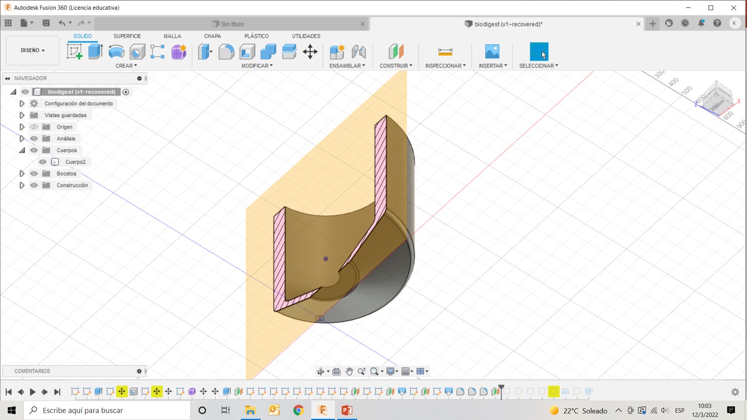
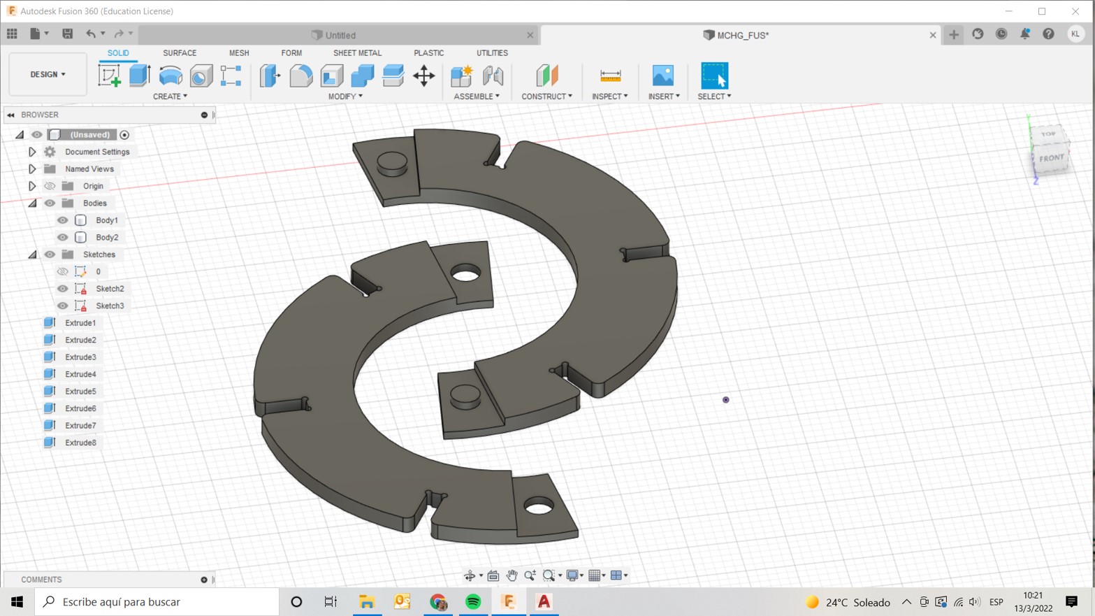
I decided to make some progress on my final project so I planned to make a mold or formwork for a biodigestor or septic tank that I was researching. I tried to copy an existing shape. In order to have the entire mold in this assignment I focused on the “red” part of the following design:
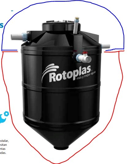
The idea is to produce the blue part in molding and casting assignment, then, the skin for all of it using nylon fibers and epoxi resine.
In order to design I used fusion and Autocad to refine the 2d design. Here you can see the main steps I followed
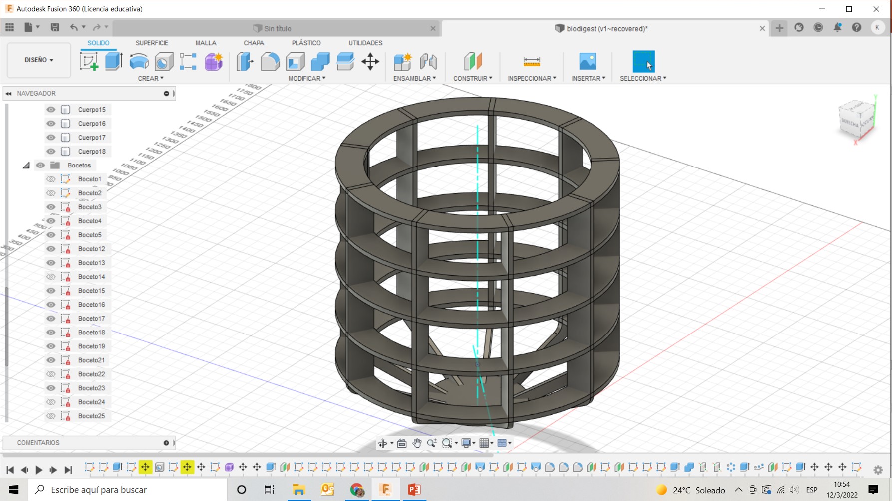
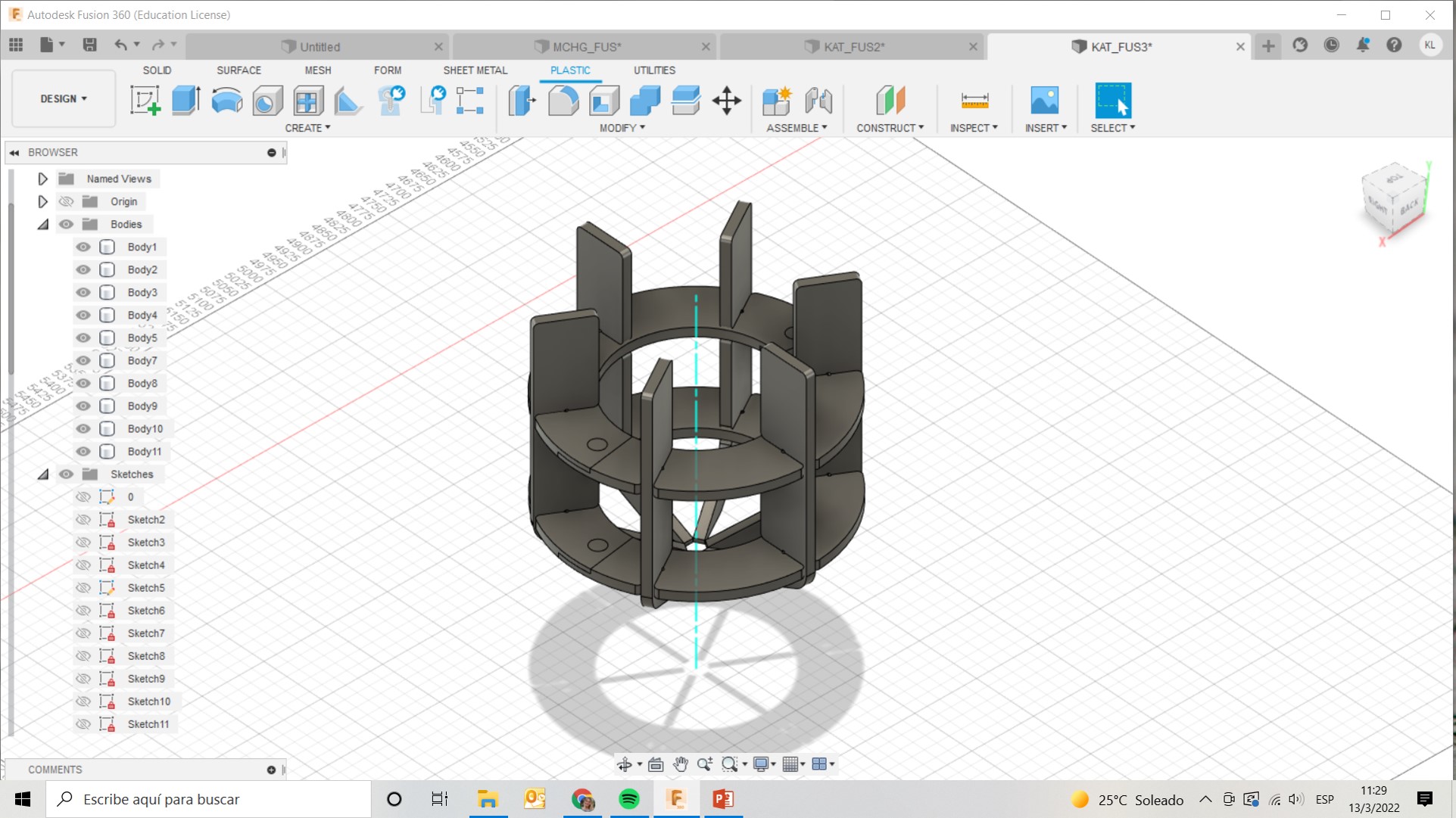
First I did a 1/6 scale of my design using the laser cutting machine and I realized I needed to produce a smaller design so I change the original design a little
Because I didn’t want to use a lot of stock I decide to divide the rings in my design, I used this joint to do so
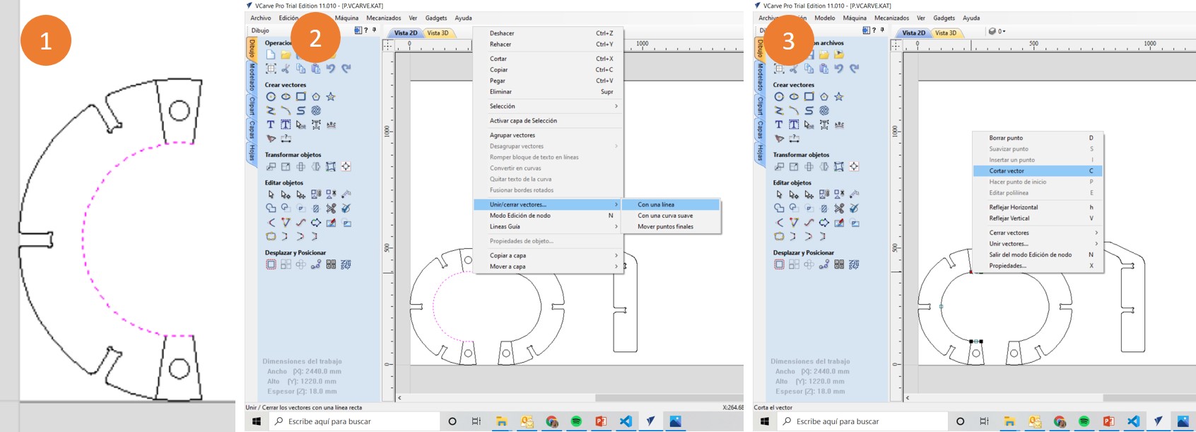
Finally I exported my design into DXF and opened it with Vcarve where I needed to verify and fix some errors with the lines not being joint. It is a common problem in vcarve but fortunatelly you can fix it there. So I did it
2. Mill
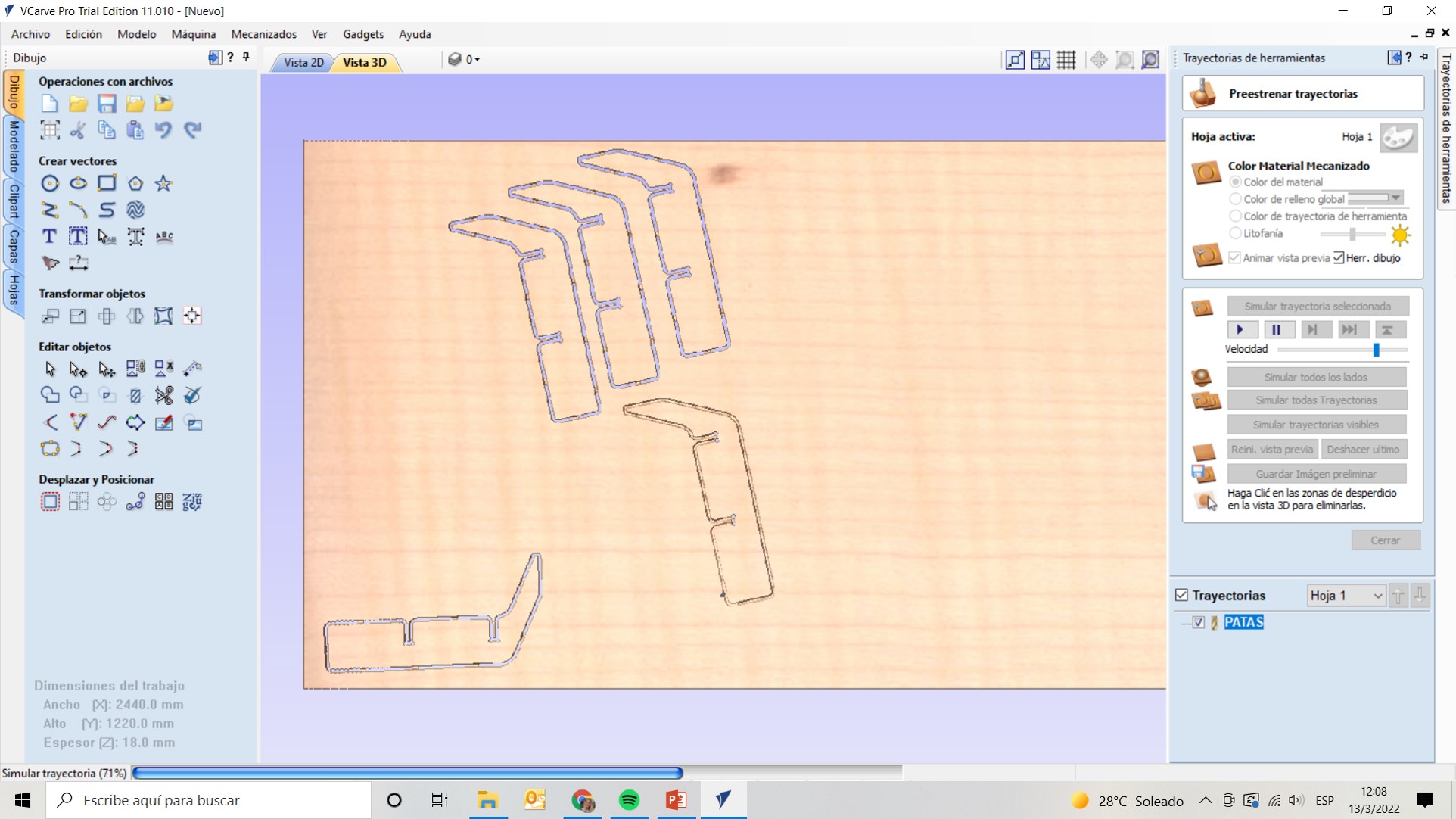
In total, I had 5 different toolpaths produced in Vcarve and sent to shopbot3:
- boxed work (to lower the thickness of the material) in the extremes of the rings
- Circles inside cutting (male and female)
- Circles outside profiling (to soften the edges of the circles)
- Rings cutting
- Vertical pilars cutting
The job lasted around 30’ to finish
3. Assemble
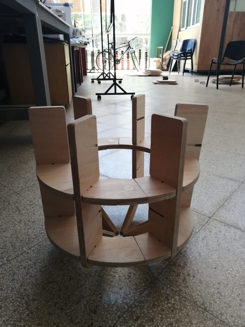
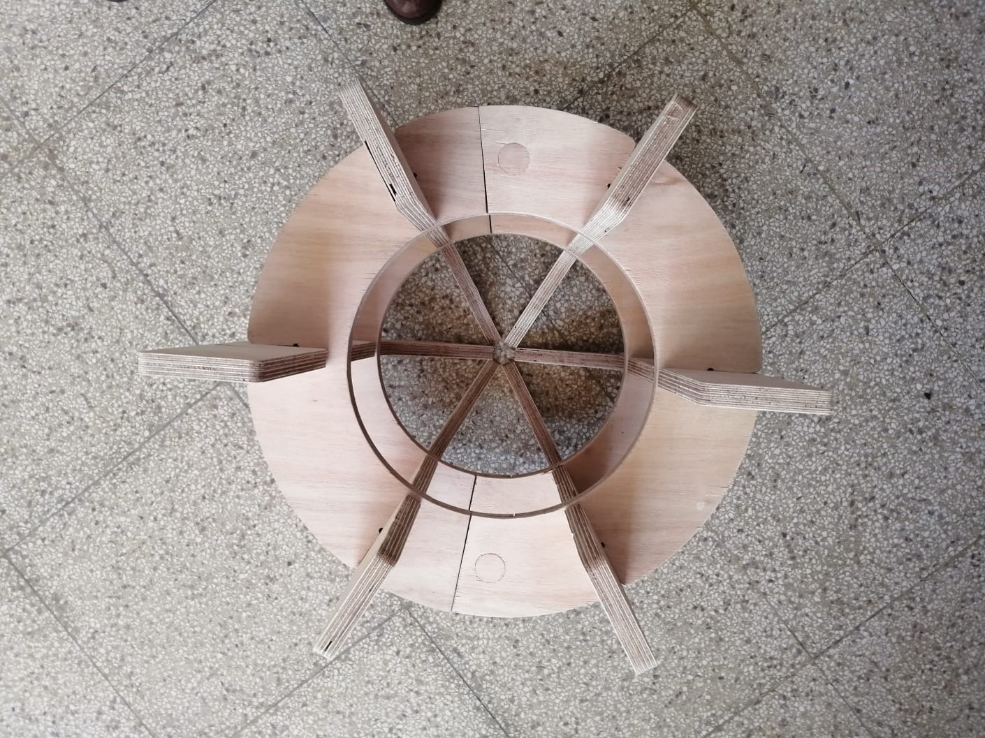
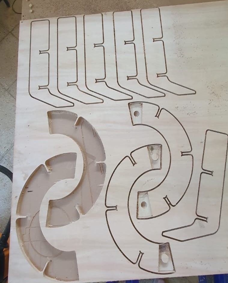
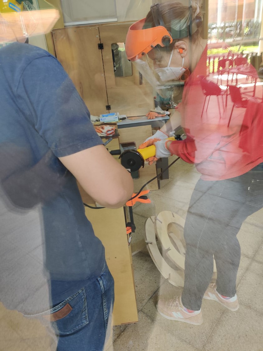
First I joined the rings, they fit perfectly but, then, when I tried to join them with the vertical pilars I realized the pressfif were so tight so I decided to use a jigsaw machine to enlarge the joints.
At the end, because the joints were still too tight the rings joints broke  so I needed to add glue. So my design intentions were good but my carpentry skills weren’t
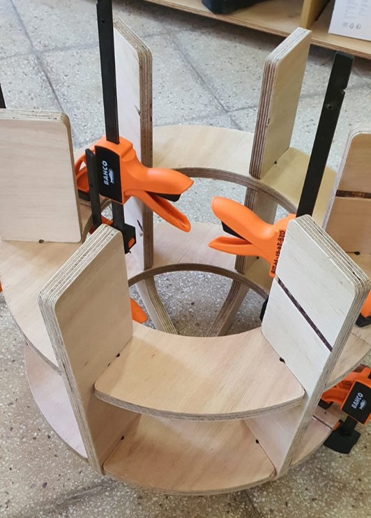
I left my mold one day so the glue could dry and there is my final result: