7. Electronics design
Group assignment: Use the test equipment in your lab to observe the operation of a microcontroller circuit board.
Individual assignment: Redraw the echo hello-world board, add (at least) a button and LED (with a current-limiting resistor), check the design rules, make it, test it.
Extra credit: Simulate its operation. Render it.
Group Assignment
Use the test equipment in your lab to observe the operation of a microcontroller circuit board.
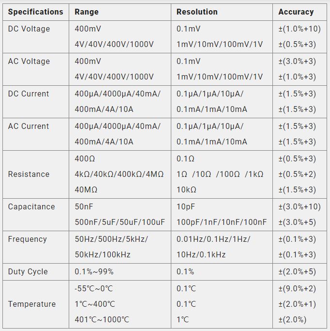
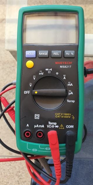
1. Multimeter
This is the most used tool so far, we used it to test the current continuity in our PCBs and to test the solder and fuctioning of the components in the circuits. It is a powerful tool and there is its specifications
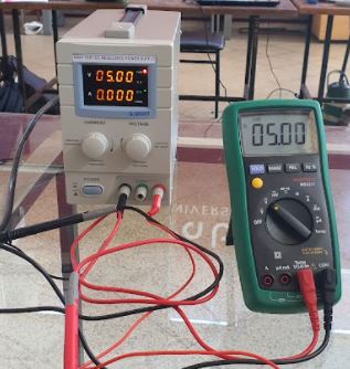
2. Power supply
We identified 3 different power supply tools: a simple power supply (30v max) a multiple power supply (where combined you can supply 50v tops) and a programmable power supply where you can ser your own parameters with a max of 30V. We also used the multimeter to test the supply obtained from each one.

4. Functions generateor and Osciloscope
We tested multiple functions using the function generator connected to the osciloscope.
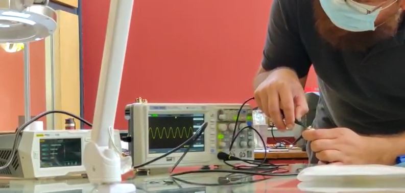
The function generator allows you to design and test 3 main variables, Voltage, wave function, current. and with the osciloscope you can visualize or hear the combinations you are testing.
Understand and use Lab's equipment = DONE
Individual Assignment
Redraw the echo hello-world board, add (at least) a button and LED (with a current-limiting resistor), check the design rules, make it, test it.
Re drawing an echo hello-world board
I decided to use ATtiny 45 as my hello-world board.
First, I identified the available components in my lab so I can, after, look for them in libraries online.
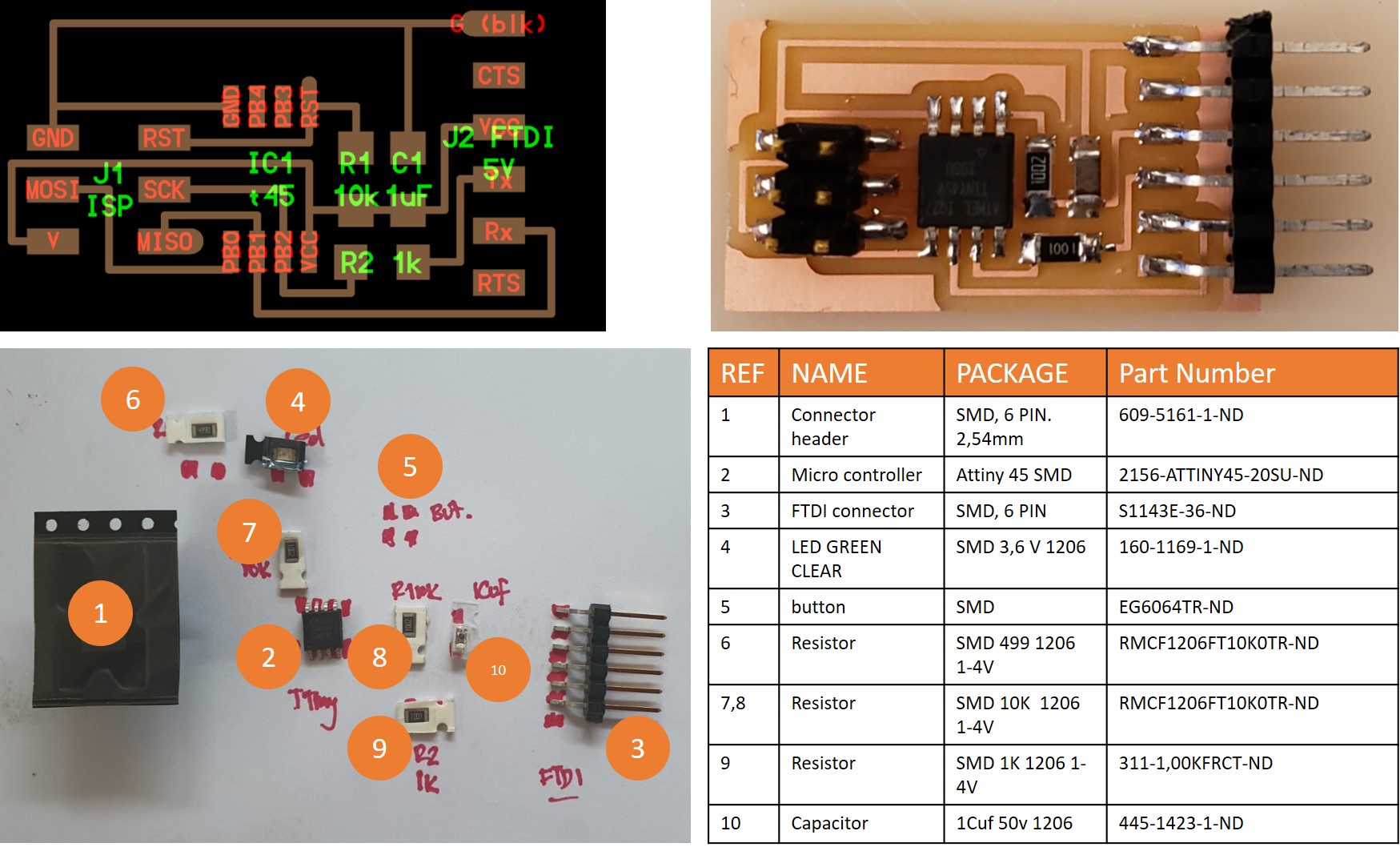
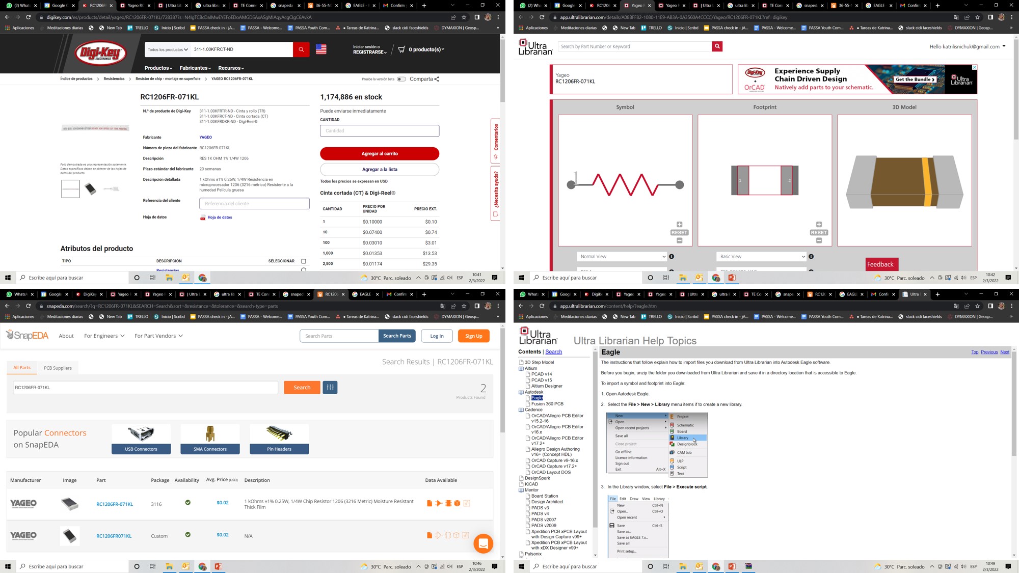
When I identified all my available components, I started to look for them in available libraries. Here you are some of the most useful ones:
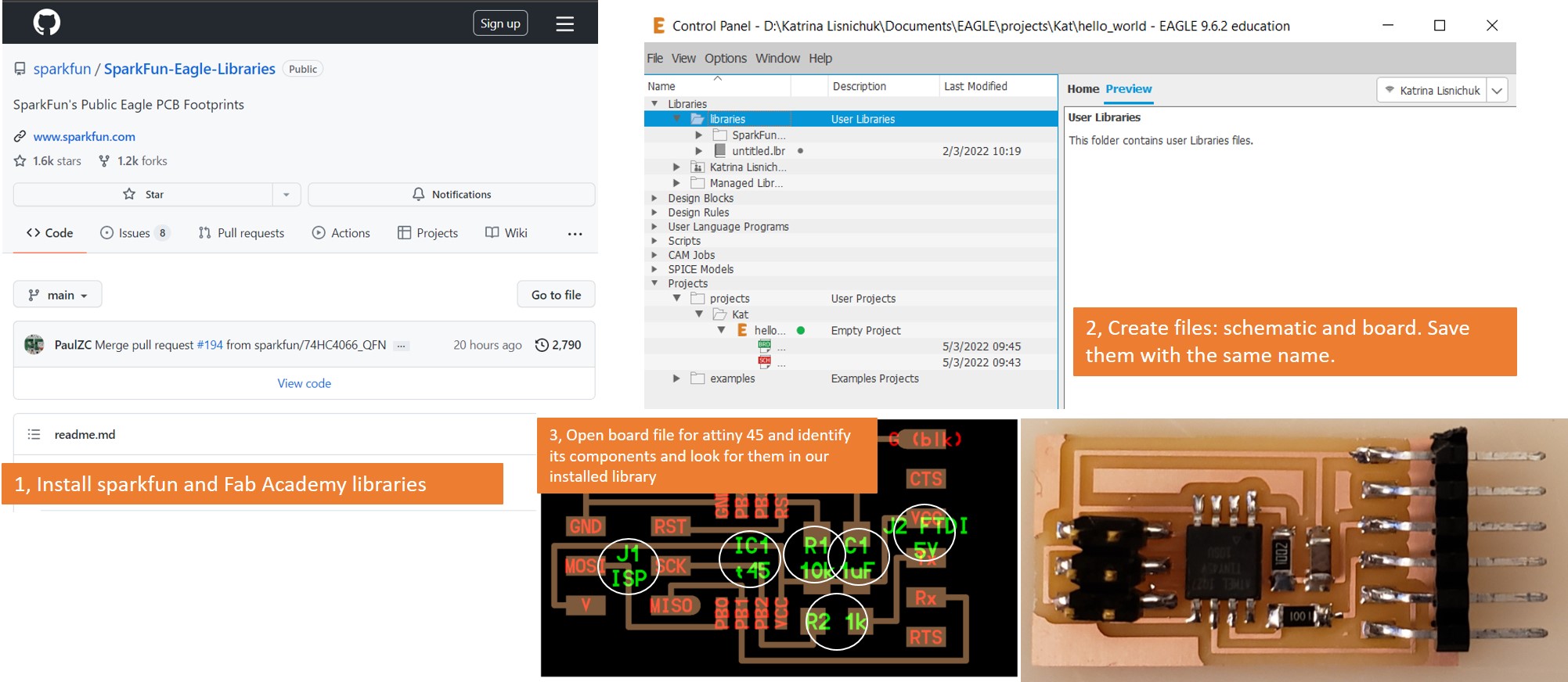
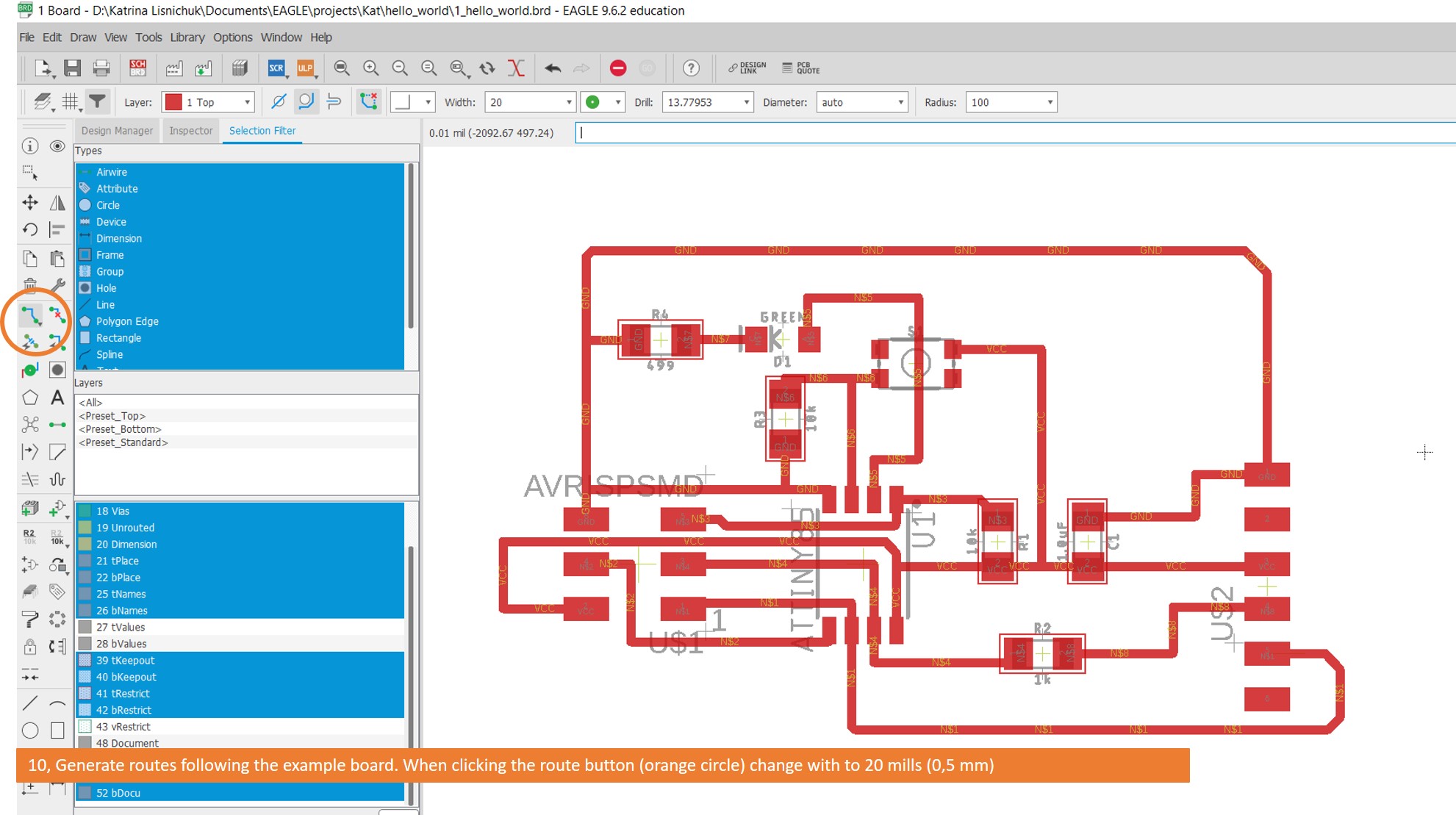
Then, I installed and started to use Eagle. In order to learn how to use ir I saw this tutorial recorded by our lab’s Instructor Abdon Troche
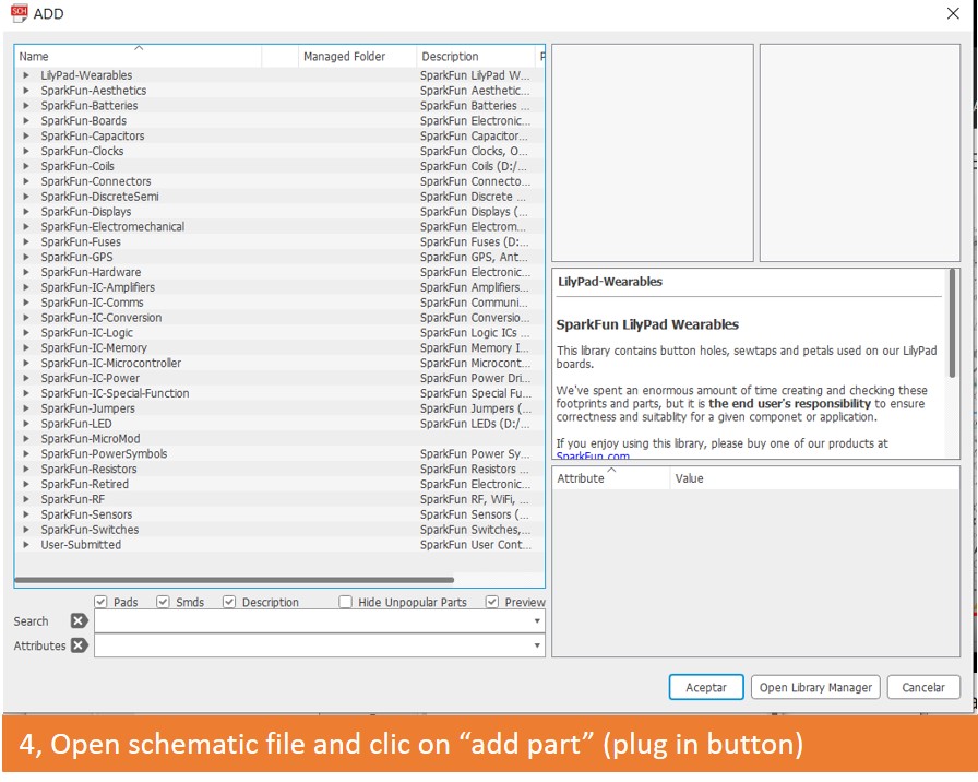
Once Eagle was installed, I followed these steps:
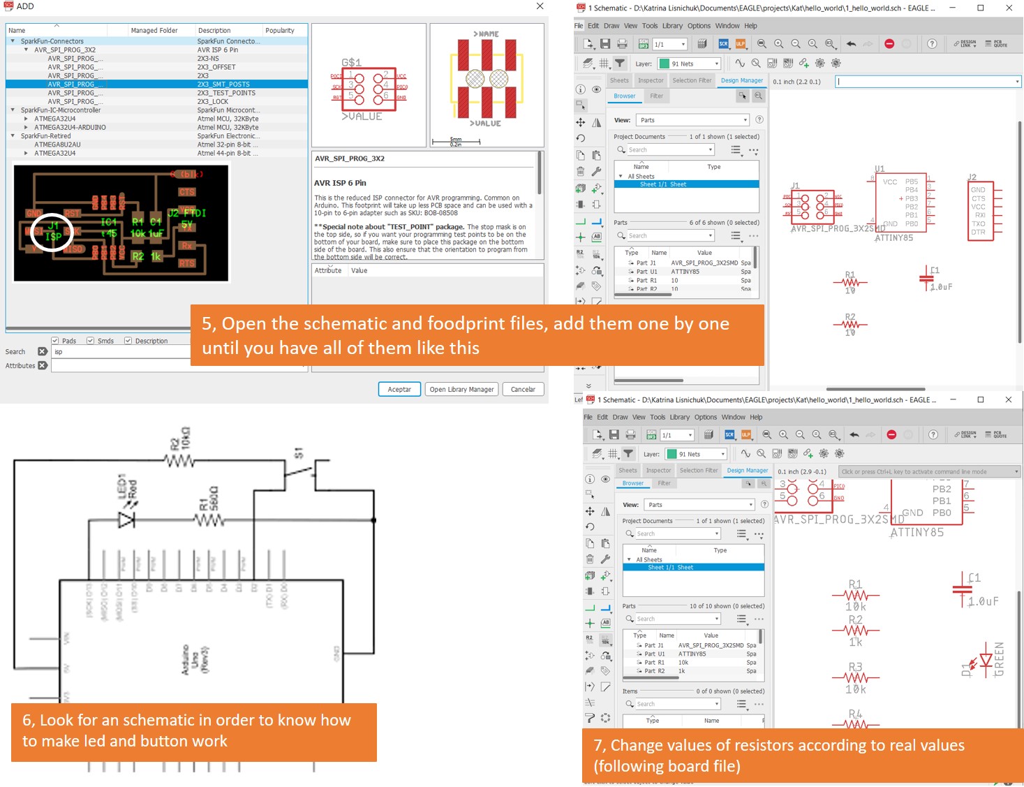
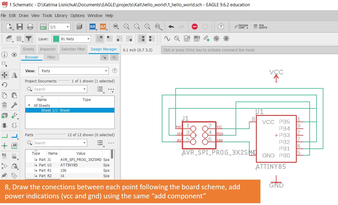
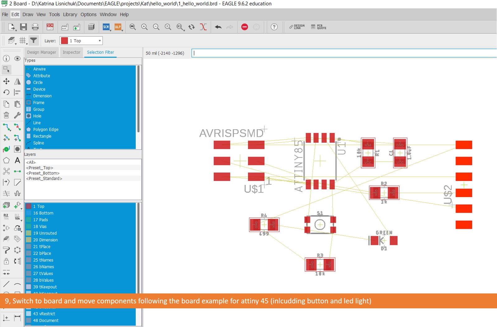
This is an exceptional documentation I found very useful
Main learnings:
- Always verify your available components, before deciding wich library is better to your project.
- Use Eagle with a mouse
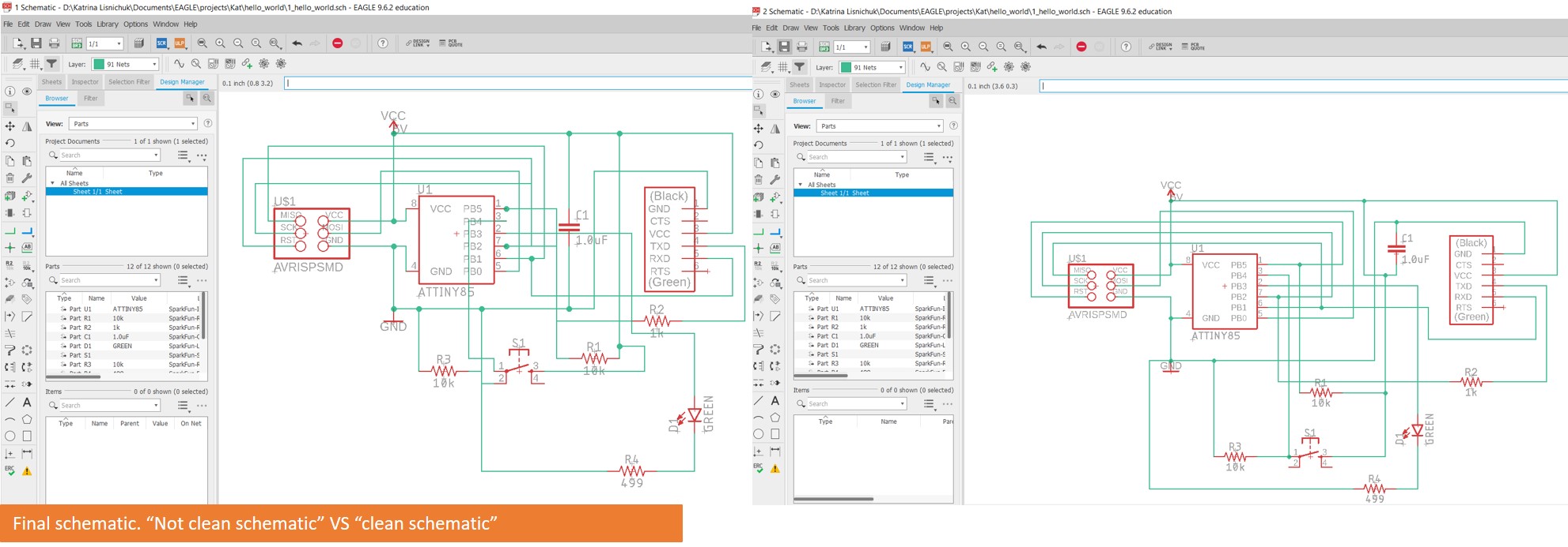
- Mind your schematic’s order and legibility (it is very important in case you need to debug or place components afterwards)
- Review your previous documentation on milling workflow so you can follow your own recomendations, it is easily forgettable and that is the purpose of having documentation in place.
- Review at least 3 times the order of your components before solder them
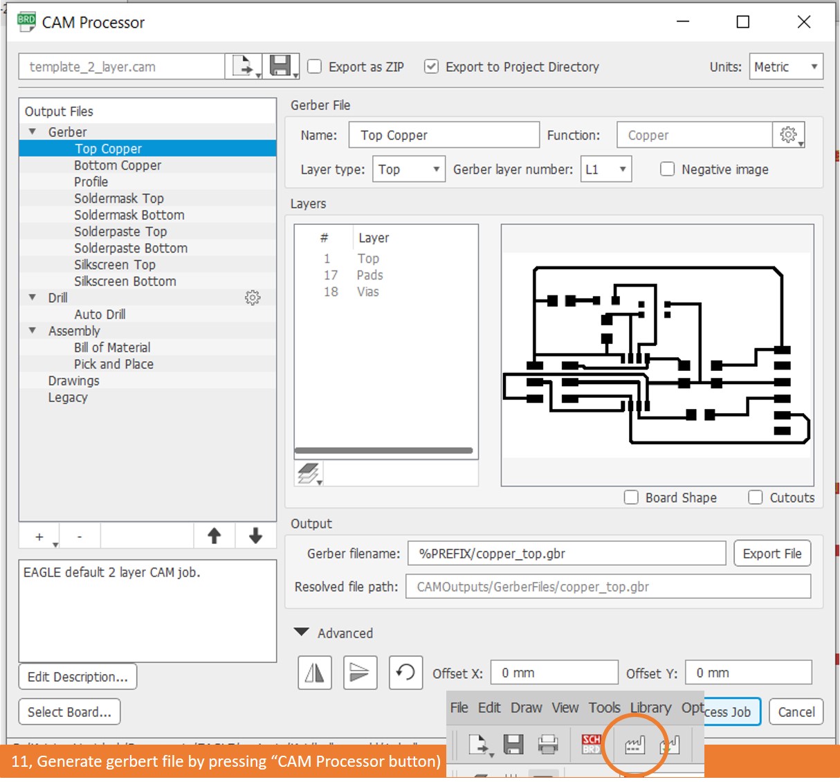
In order to machine and solder my board I used the exact workflow used on electronics production week. This is the workflow
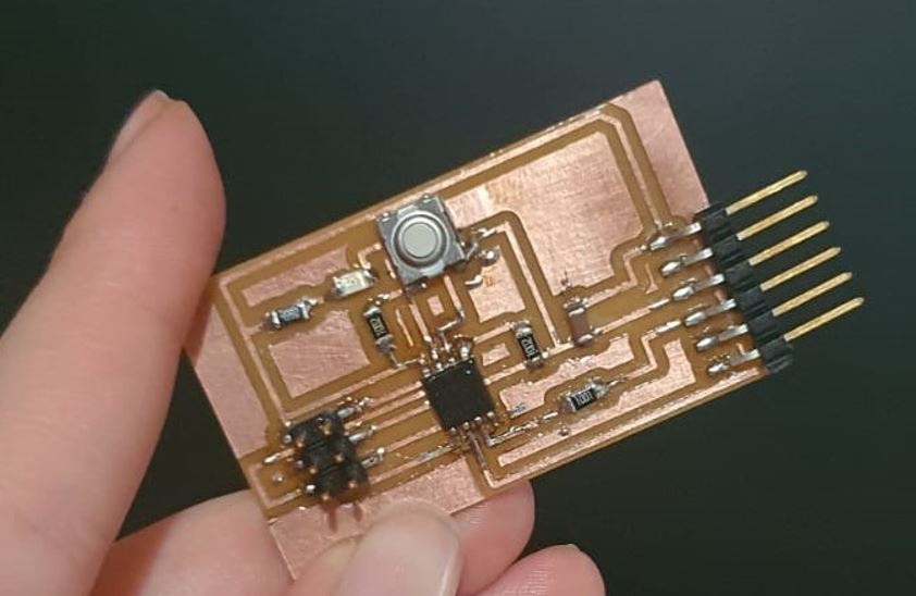
Final PCB board
Programming and testing
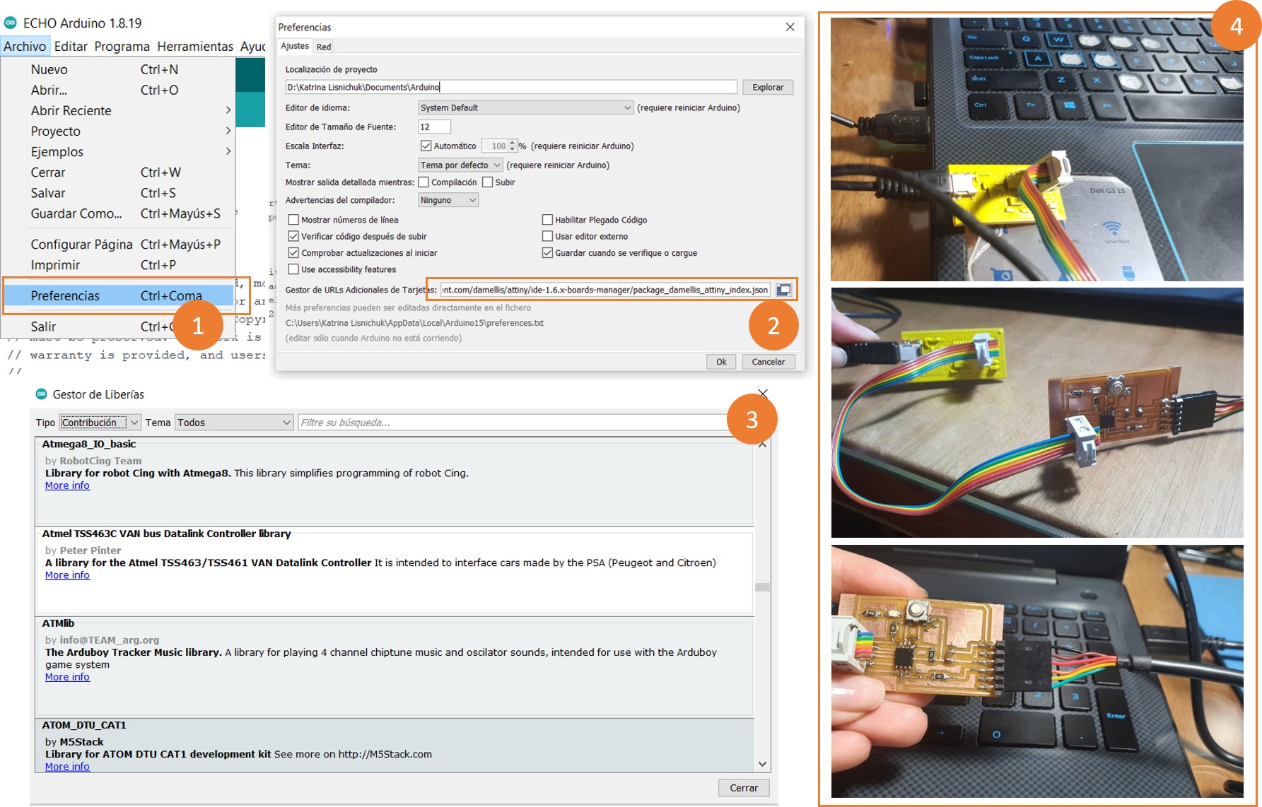
I used IDE Arduino uno on windows to program my board this is the link to download it
Then I follwed these steps
- Open Arduino and go to preferences
-
Add the following text on the marked bar:
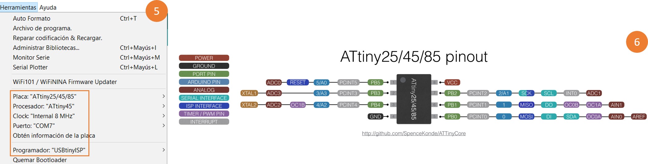
https://raw.githubusercontent.com/damellis/attiny/ide-1.6.x-boards-manager/package_damellis_attiny_index.json 3. Install Attiny board on Arduino IDE by adding attiny by david A. Mellis on the board manager 4. Plug your programmer and board in to the computer. I used the programmer produced on electronics production assignment (USBISP, the yellow one you can see in the picture) 5. Set your board (In my case ATtiny 85/45/25), microcontroller (in my case ATtiny 45), programmer (In my case USBtinyISP)and clock (1MHZ). 6. Identify your microcontroller pinouts using the data sheet. In my case, I used this is one
Blinking code
Use the three backticks to separate code.

oid setup() {

  pinMode(3, OUTPUT);       //setting Pin 2 LED as output

}

void loop() {               // ------ Event loop ------ //

  digitalWrite(3, HIGH);    /* Turn on seventh LED bit/pin in PORTB */
  delay(50);              /* wait */
  digitalWrite(3, LOW);     /*Turn off seventh LED bit/pin in PORTB */
  delay(50);              /* wait */

}                           /* End event loop */
Blinking working
Button code
const int BUTTON = 4;
const int LED = 3;
int BUTTONstate = 0;

void setup()
{
  pinMode(BUTTON, INPUT_PULLUP);
  pinMode(LED, OUTPUT);
}

void loop()
{
 BUTTONstate = digitalRead(BUTTON);
  if (BUTTONstate == HIGH)
  {
   digitalWrite(LED, HIGH);
  }
  else{
    digitalWrite(LED, LOW);
  }
}
Button working
Echo hello-world code
  void setup() {

pinMode(3, OUTPUT);       //setting Pin 2 LED as output

}

void loop() {               // ------ Event loop ------ //

  digitalWrite(3, HIGH);    /* Turn on seventh LED bit/pin in PORTB */
  delay(50);              /* wait */
  digitalWrite(3, LOW);     /*Turn off seventh LED bit/pin in PORTB */
  delay(50);              /* wait */

}                           /* End event loop */
With this last excercise I had a problem: When I wrote something, It appeared an echo of it but with some many other characters, we think this is due to something with arduino’s interpretation of characters. But it is still echoing things you write!
