13. Input Devices
individual assignment:
Measure something: add a sensor to a microcontroller board that you have designed and read it
Selected sensor and why
I decided to use a sted response sensor, specifically a transmit-receive one because I wanted to test if I could use it to measure the level of water inside a septic tank in order to advance towards my final project.
Board Design
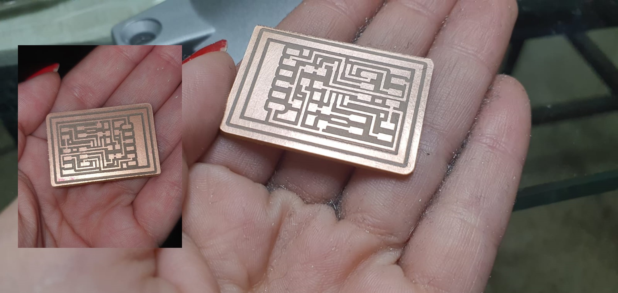
I did a new board following the example of Neil, I did the hello.txrx.45 board. I followed these steps in order to achieve it:
I recalled the first week of electronics design where I learned how to use a PNG and convert it to a gerber file, because in this case I just wanted to replicate Neil’s board as it is.
- Invert the PNG file called “traces” in GIMP and get to know the pixels in px/inches always in GIMP.
- Import an image as an object in Flatcam writing the size of the image (1269 px/in)
- generate the cutting geometry using an 1/64 endmill, 3 passes and 50% overlapping
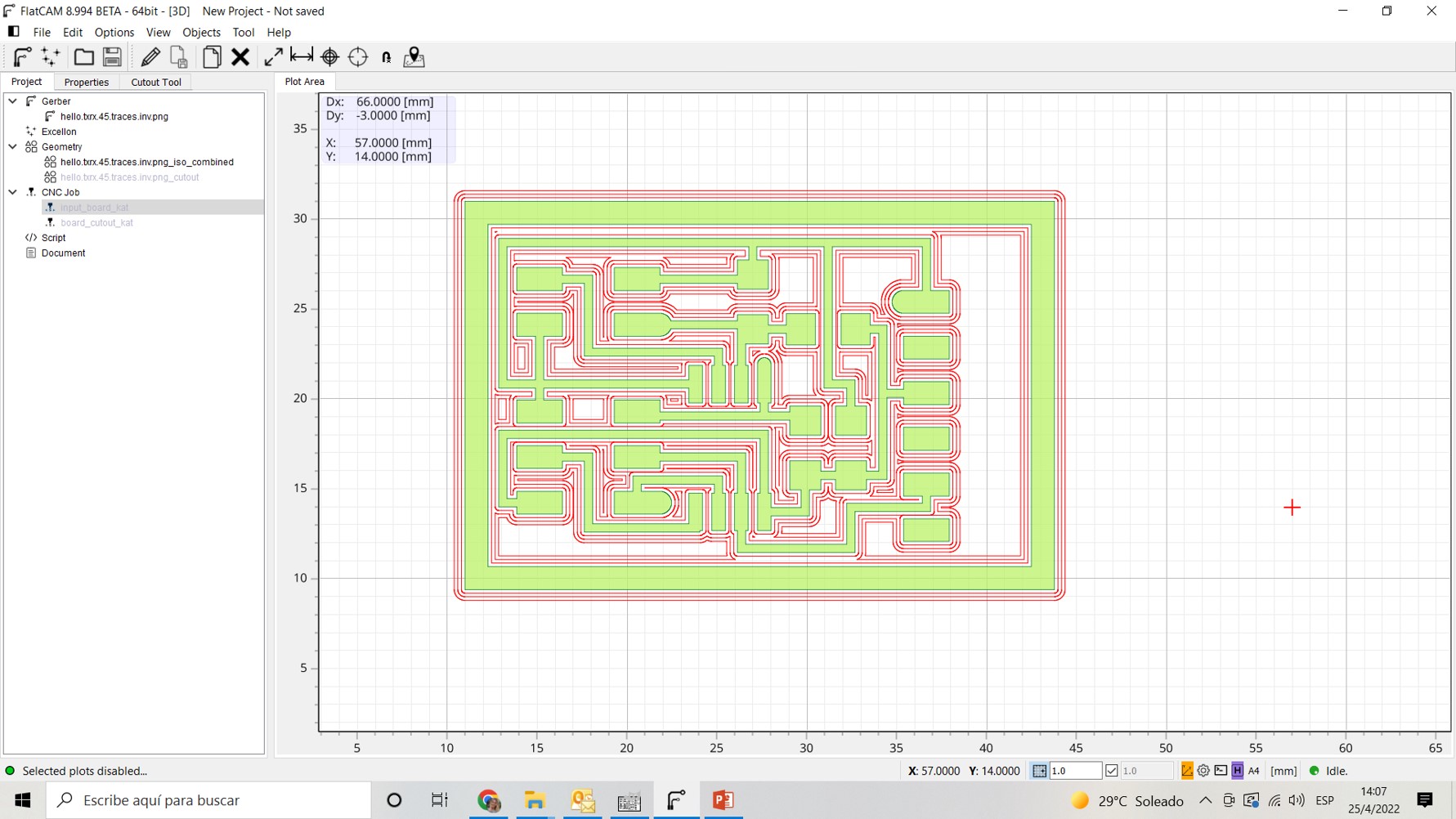
- Gererate the cutting road and verify that the mill passes everywhere as expected.
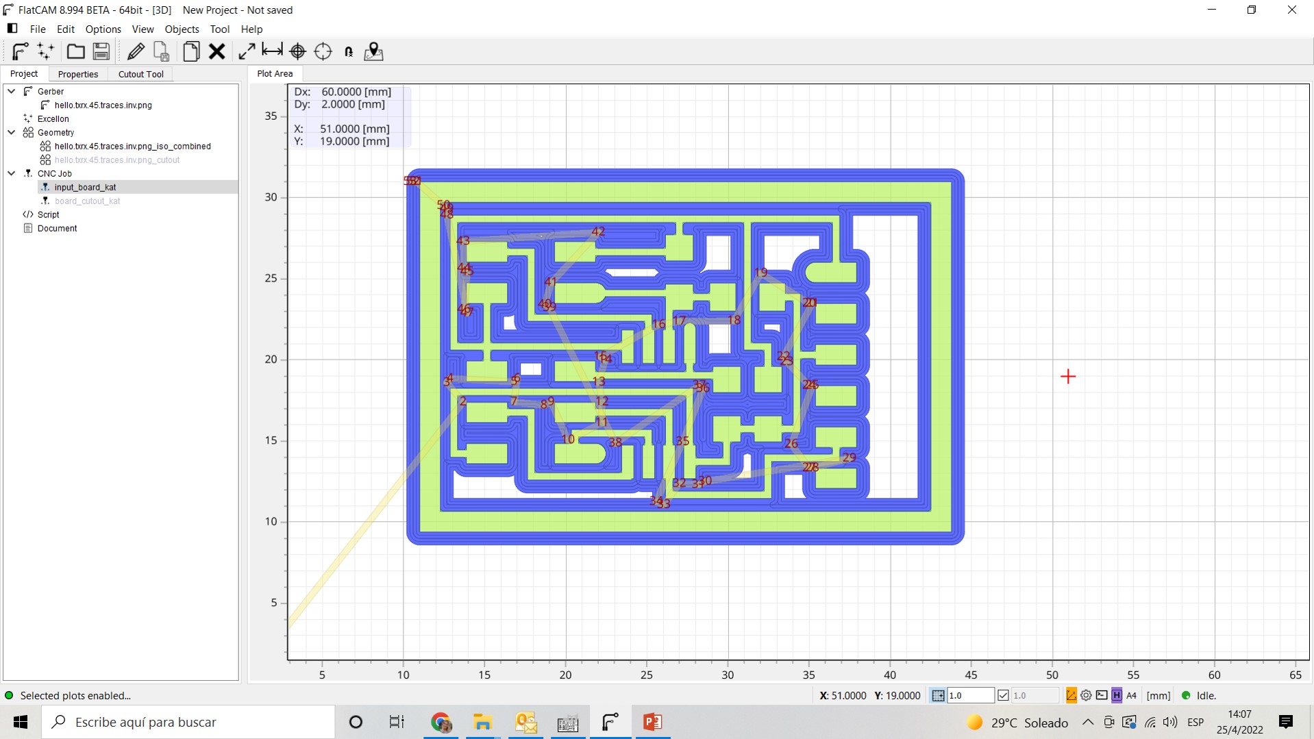
- Generate the cut out geometry and cutting road

- Generate a NC file in order to send the code to the milling machine
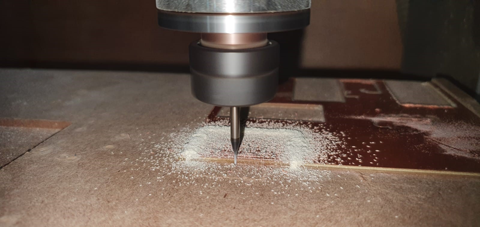
Board production
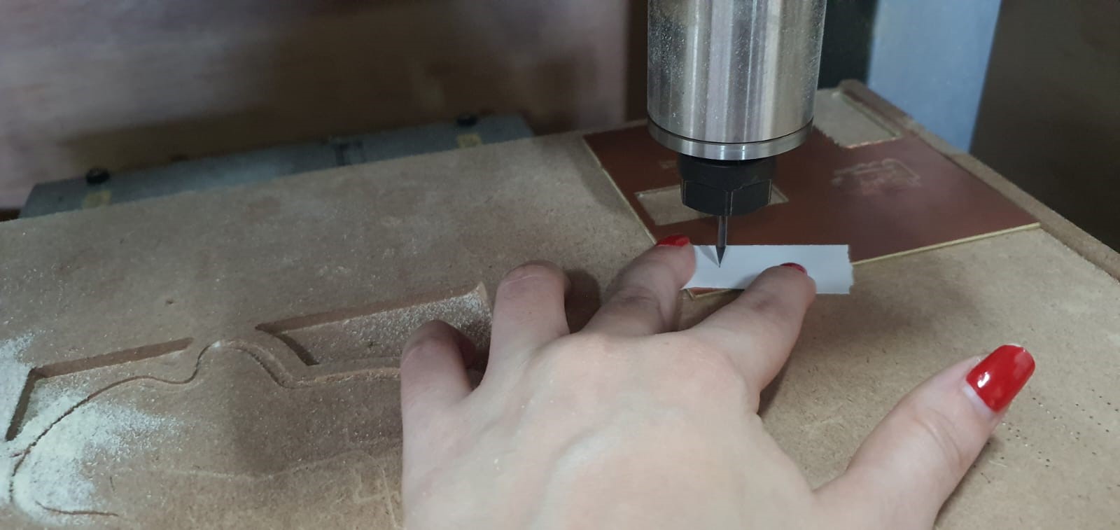
- Leveling X, Y and Z manually using a paper to detect the correct Z for the 1/64 end mill
- Start milling the board using the first file NC code generated
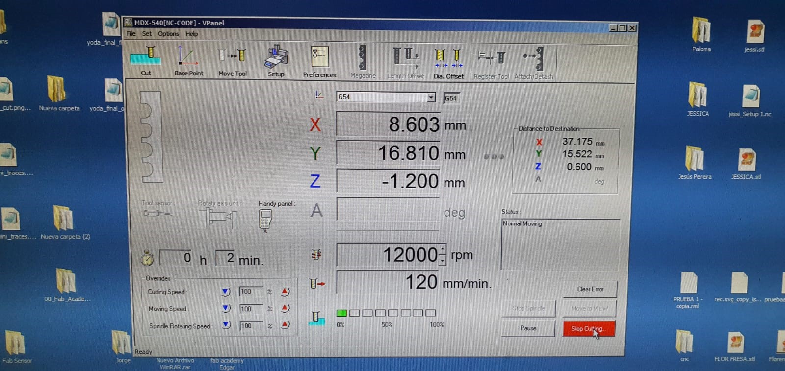
- change the endmill to 1/32 to do the final cut out of the board. I had to use all my eye precision to use the copper pcb wisely and efficiently. Actually, It wasn’t necessary to cut one side of the board because of it haha
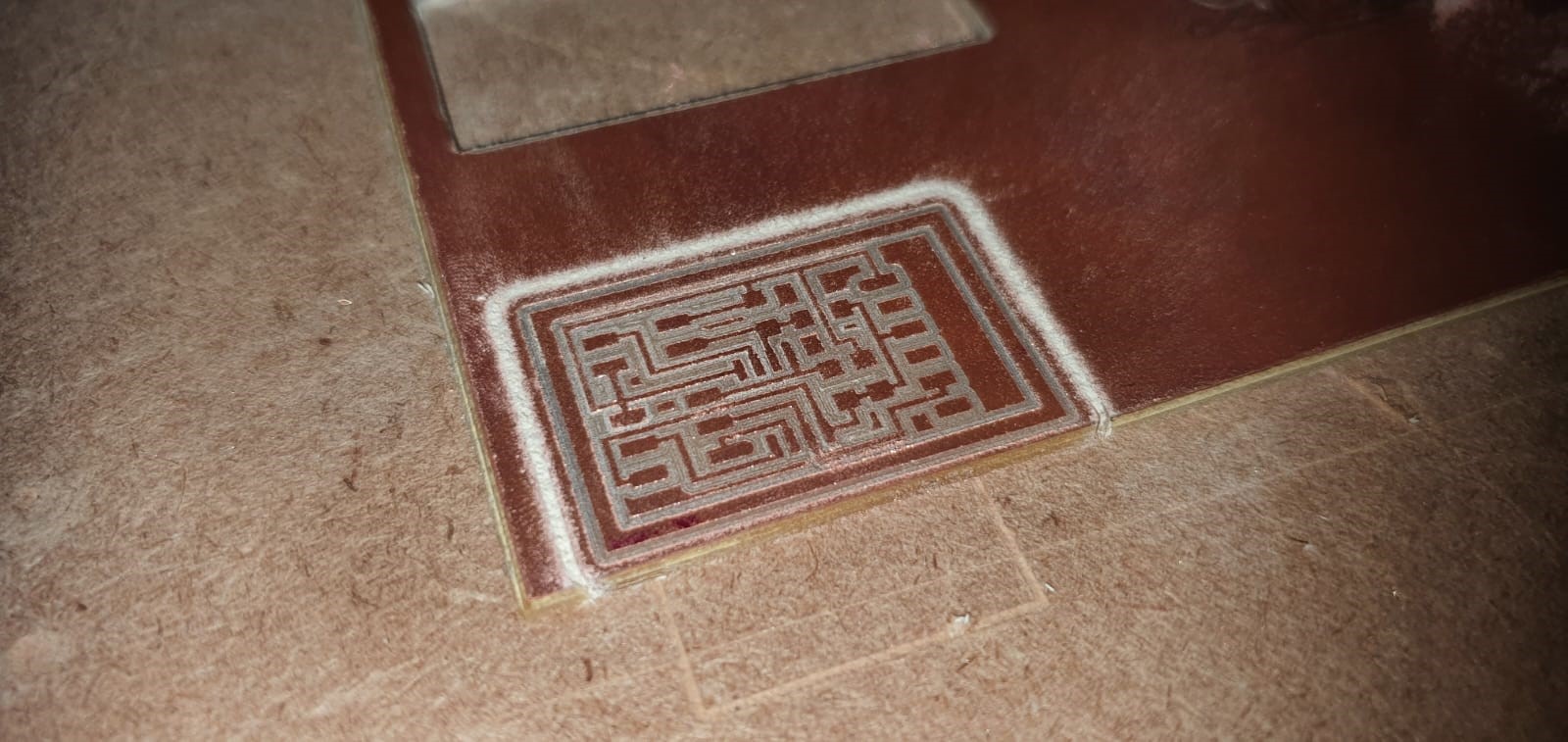
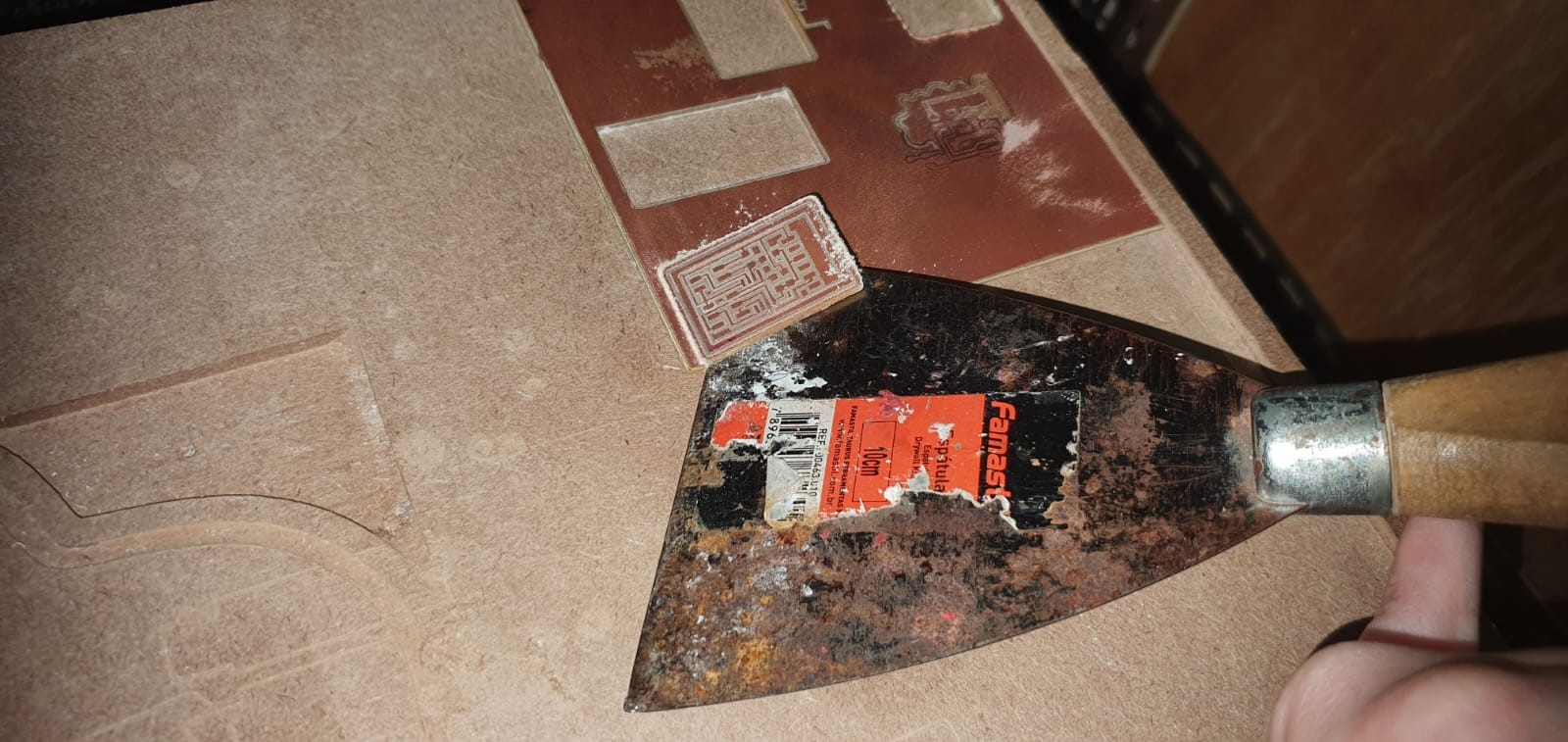
- Finally, get the board out of the machine cam and clean the board using a metal sponge
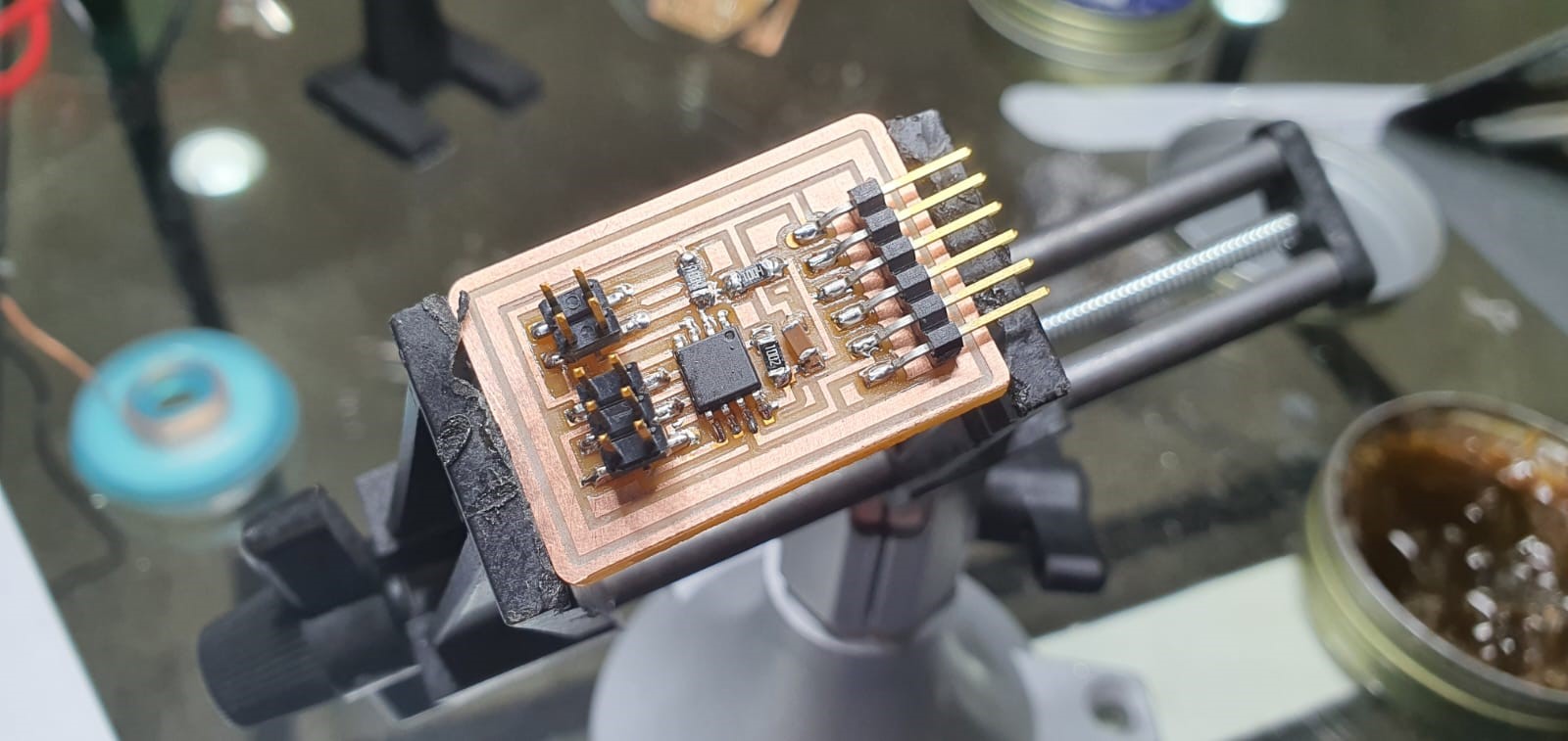
Board soldering
- Search and identify the electronic components for the board
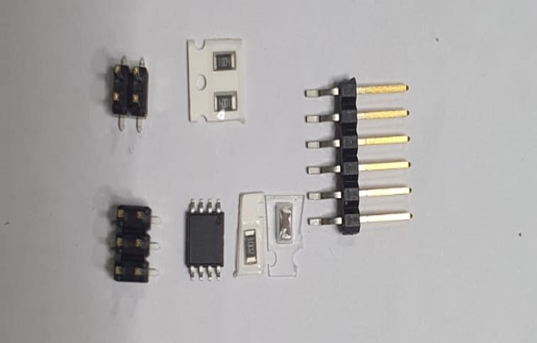
- Patiently solder all of them
Programming
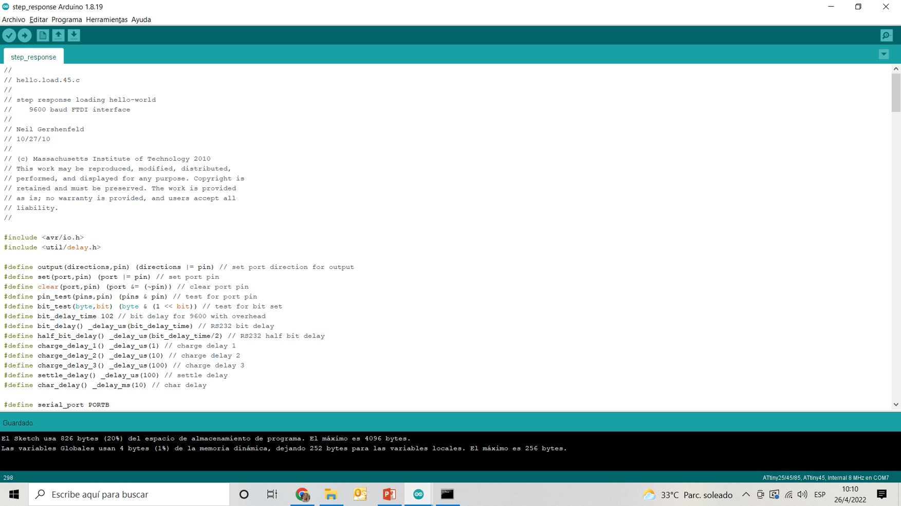
- In order to program my board, I used Neil’s C code in arduino one
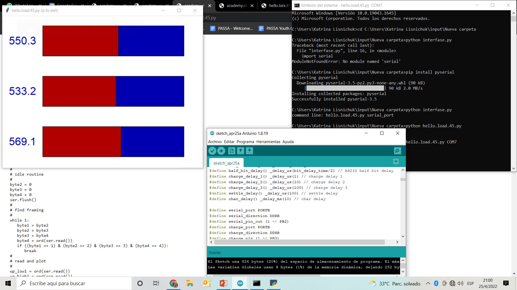
- I used my own programmer a tinyUSBISP and in order to test the transmit-receive of the sensor (2 little pieces of copper pcb boards) I needed to run a python code to generate a measurement canvas.
- To do so, I copied Neil’s Python file and first create a new note pad file containing Neil’s code, and then I changed the file extension from .txt to .py and called it the same as Neil called it. “hello.load.45.py” because the code relates the name of the file in order tu run the code inside with python.

- Open cmd terminal and install pyserial using this line:
pip install pyserial
It seems like this:
    C:\Users\Katrina Lisnichuk\input\Nueva carpeta>pip install pyserial
    Collecting pyserial
    Downloading pyserial-3.5-py2.py3-none-any.whl (90 kB)
     |████████████████████████████████| 90 kB 2.0 MB/s
    Installing collected packages: pyserial
    Successfully installed pyserial-3.5
- Run the file with Python using this line:
python hello.load.45.py COM7
Succes videos
- Testing the transmit-receive sensor using 2 pieces of copper boards
- Testing the transmit-receive as it would be in a “water tank”
Files
Last update:
April 27, 2022