5. Electronics production
Group Assignment
This week we had a group and a individual assignment. For group assignment we had to: 1. Characterize the design rules for our in-house PCB production process
Milling machine
About the machine
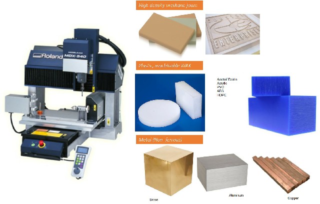
We used a MODELA PROLL MDX 540
CAM size: 40x50x15 cm
3 axis
Tests and steps
We did 2 end mill test, first we used a 1/32 inch mill and then, we used a 1/64. We decided to use the 1/32 for cutting and 1/64 for milling. we used FlatCAM as CAD tool and generated NC codes for our machine to read and cut we used a vaquelite copper plate as PCB. you can see the main steps we followed and the results of the 2 tests we did in the images below
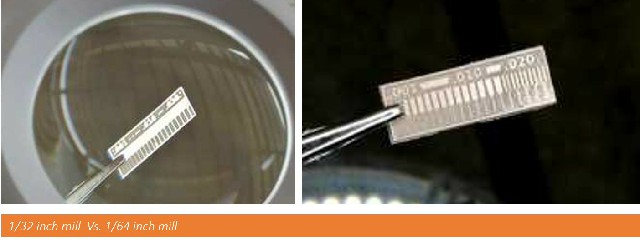
For testing we used XY speed: 132 and Z speed: 60
Warnings!
- When generating NC code, be sure you erase the line in your code containing “M6” and be sure you also add the spindle rpm (we used 7000)
Individual Assignment
Make an in-circuit programmer that includes a microcontroller - mill and stuff the PCB - test it to verify that it works
We decided to make a USB-t44-ISP, using AMTEL ICE and Arduino as programmers.
PCB Milling steps
Having a gerbert file 1. Download FlatCAM software. I used this customized tutorial to do it 2. Download the PNG PCB file for FabISP (USB-t44-ISP) 3. Invert the PNG image on GIMP 4. determine the resolution of the PNG on GIMP in PIXELS/INCH 5. Import the PNG file on FlatCAM (write the correct resolution before import the file)
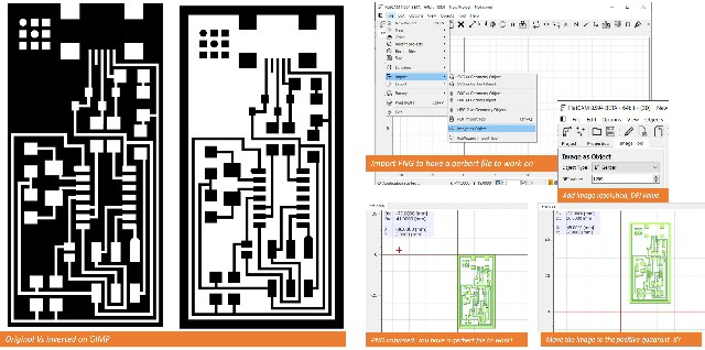
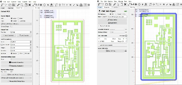
Having a NC code to machine the PCB 1. run the isollation tool on the gerbert design. Here I defined the end mill (1/64 inches) I added this value in mm (0.396). Also defined the passes (5) and the overlapp % (10) this last one could be a little less. 2. Generate geometry and see the coverage of the line passes. Here I realized that one part in the design was uncovered so I changed the end mill size to 0.38 (just a little trick to make the end mill pass trough the area we need) and it worked 3. Go to “project” and make double click on the new geometry file was generated and define the end mill size and speed rates (XY, Z and spindle) I used 132 for X and Y, 60 for Z, and 7000 rpm for spindle. 4. apply all parameters and Press generate NC code 5. Open the NC code with note pad and erase “M6” line. Save.
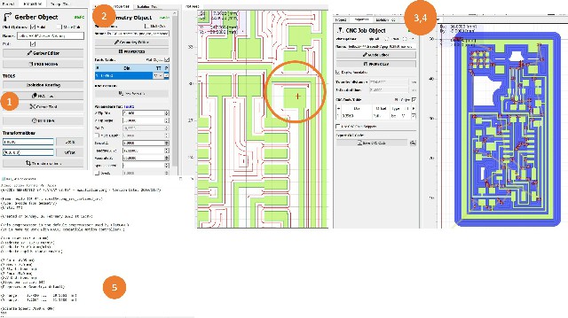
Having a cut out file 1. double click on your original PNG file on “project” on FlatCAM and pres cut out tool 2. define the mm of the offset and the mm of your end mill (in this case I used a 1/32 inches end mill) Be aware of the depth of your material here, In my case my stock is 1,6mm so I define a cut depth (-z) of 1,8mm 3. Generate geometry 4. Double click on the new geometry generated on “project” and generate a new NC code file. using the same parameters (1/32 end mill and same speed rates as the last NC file) 5. Open your Nc cut out code with note pad and erase the “M6” line.
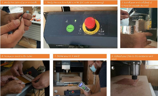
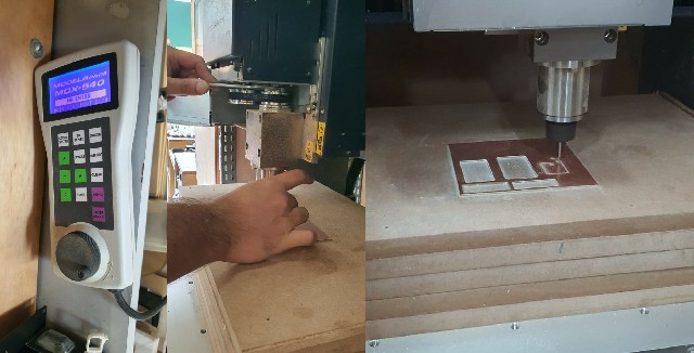
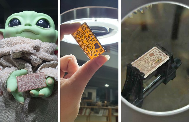
Milling the PCB 1. Send the file to the machine’s computer 2. Upload the file to the software 3. Install 1/64 inches end mill. Set XYZ origins. I set z using the manual control of the machine first but also tried to set it using the software, it worked both ways. Be aware when setting the Z origin, slower the rates as you are getting closer to the table to avoid crushing the end mill. I used a thin paper to measure the right Z. 4. Press start on the software 5. Verify id the machine is engraving the stock or not. If not stop it when the level on the software shows -0.05 on z and define this level as new z origin. repeat this procedure as needed until you can see the machine actually milling your pcb. 6. When milling stops, change the end mill, define the Z origin again and repeat the entire process with your NC code for cutting out the PCB from the stock. 7. Verify the results against a light and clean any loose cooper with a hand tool.
You can see the results in the images below. Baby Yoda helped provided us with the force we needed 
Soldering Components
- Wash the PCB, first I used a spry contact cleaner and then steel wool.
- Put some flux on your PCB
- Set your soldering tool, tin, flux, magnifying glass, lights, components instruction map, and bracket ready
- Identify all the components you need based on the components “map” I used the file provided in the repository for a USB-T44-ISP.
- start soldering by putting tiny ammounts of tin where you want to hold each component, then place the component and apply heat with the solder to melt the existing tin and stick the component to the board, apply more tin if you see the soldering is still week. Start with resistances (easiest ones) and end with the most difficult component (tiny usb entrance)

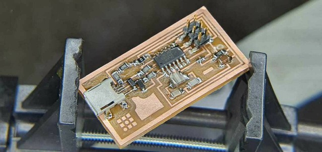
Here you can see the final USB-t44-ISP
Testing power and programming
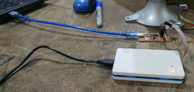
- Plug in the programmer and PCB, both connected to a computer.
- in an AMTEL ICE programmer, having a green and red light like the photo, means the circuit is operable, so I did the soldering right!!
- For programming, first as a team, we tried use AVRDUDESS in windows but an error ocurred constantly. The error said “devide not detected” even though we tried many times changing the parameters and following tutorials, nothing worked, so we decided to move to linux.
- We follow the steps mentioned in the repository but another error presented when running the “make fuse” code.
- We tried changing our programmer
- We tested the programmers again and finally we decided to go on with linux.
In order to programme I follow this steps:
-
first I run the following commands to setup my local environment:
sudo apt-get install flex byacc bison gcc libusb-dev avrdude sudo apt-get install gcc-avr sudo apt-get install avr-libc sudo apt-get install libc6-dev -
Then I downloaded the FabISP firmware and extracted it in my assignment’s folder. Then I opened the Makefile file and modified the following line:
AVRDUDE = avrdude -c atmelice_isp -P usb -p $(DEVICE) # edit this line for your programmer -
Then I opened this folder in my terminal and ran the commands shown below to program the board:
make clean make hex make fuse make program -
All the commands shown above executed succesfully and I finally could program my board