Final Project: Shadowhouse
What does it do?
Shadowhouse is a vertical farming device, intended to help produce more food in less space. The structure responds to light levels: it closes blinds as a response to more elevated light levels, or opens them as a response to less light. This is logical in a subtropical context where excess isolation is a common problem.
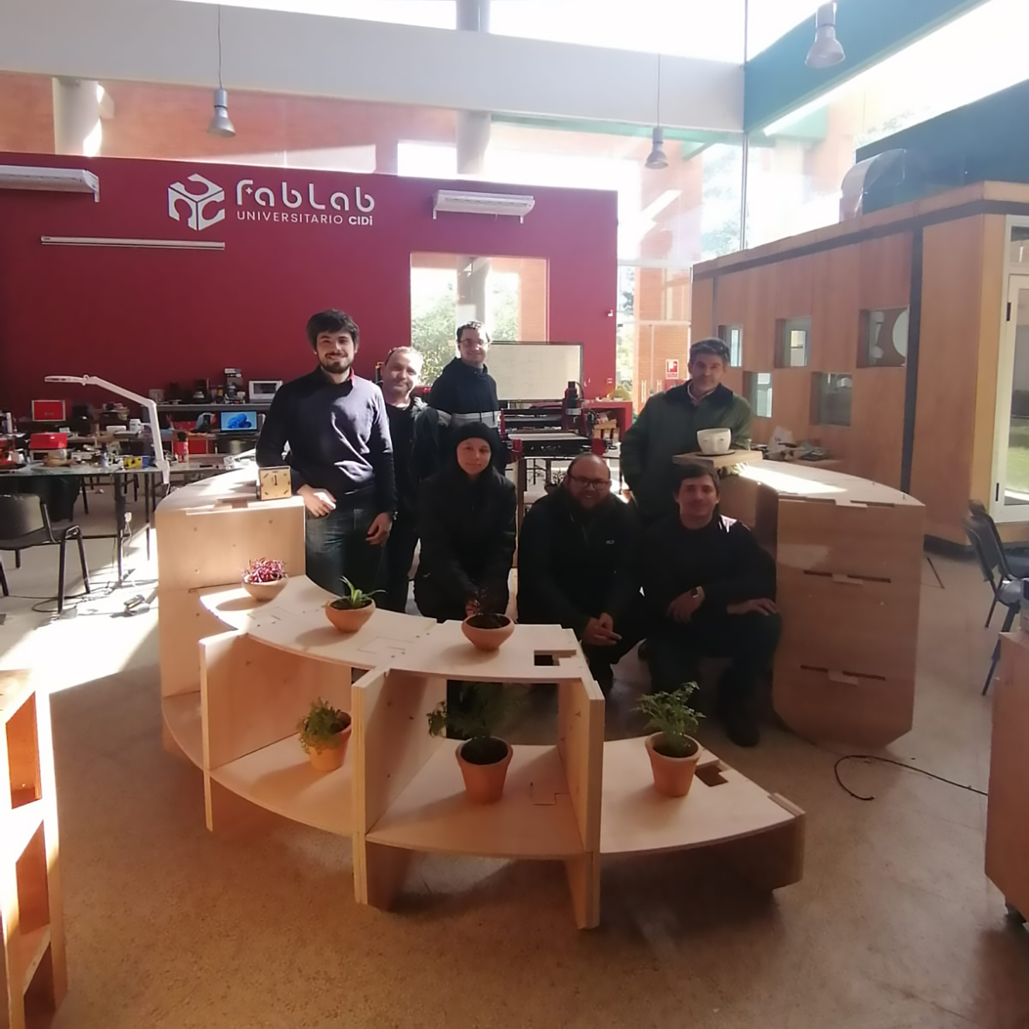
Image: Shadowhouse, and the Fab Academy 2022 class - From left to right (standing) Victor Ughelli, Juanca Cristaldo, Edgar Arévalos and Jorge Roig - From left ot right (sitting) Silvia Lugo, Abdón Troche and Hans Penner
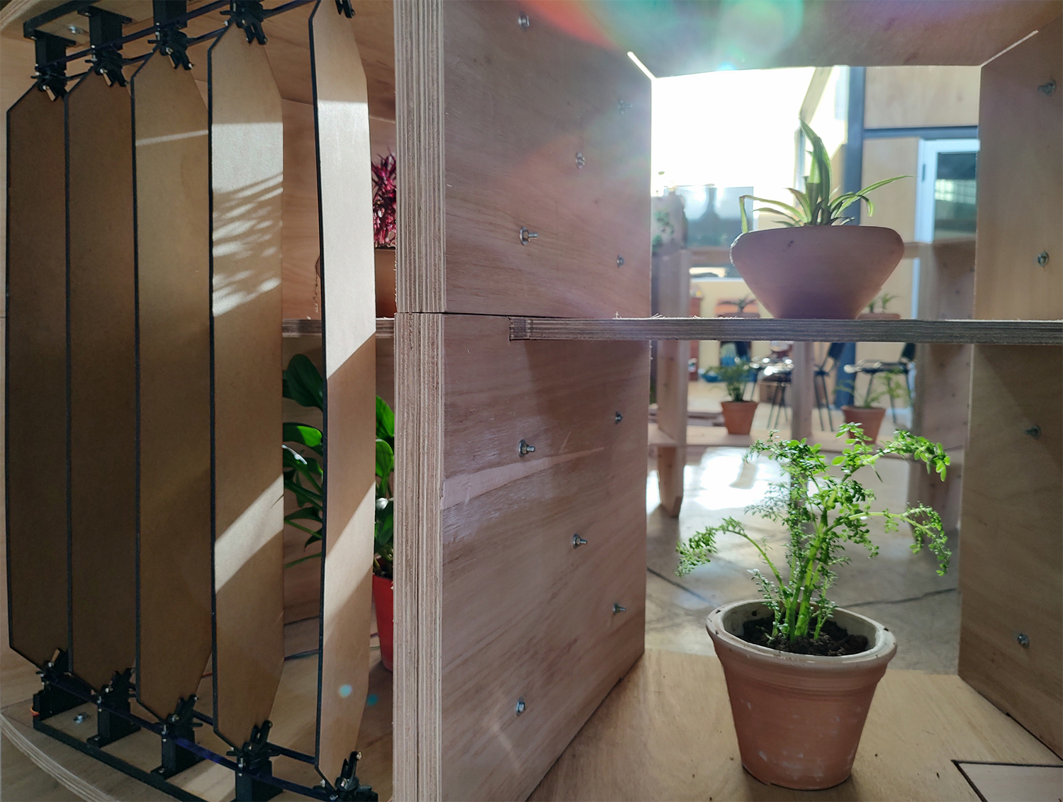
Image: Shadowhouse, built operational module
Who’s done what beforehand?
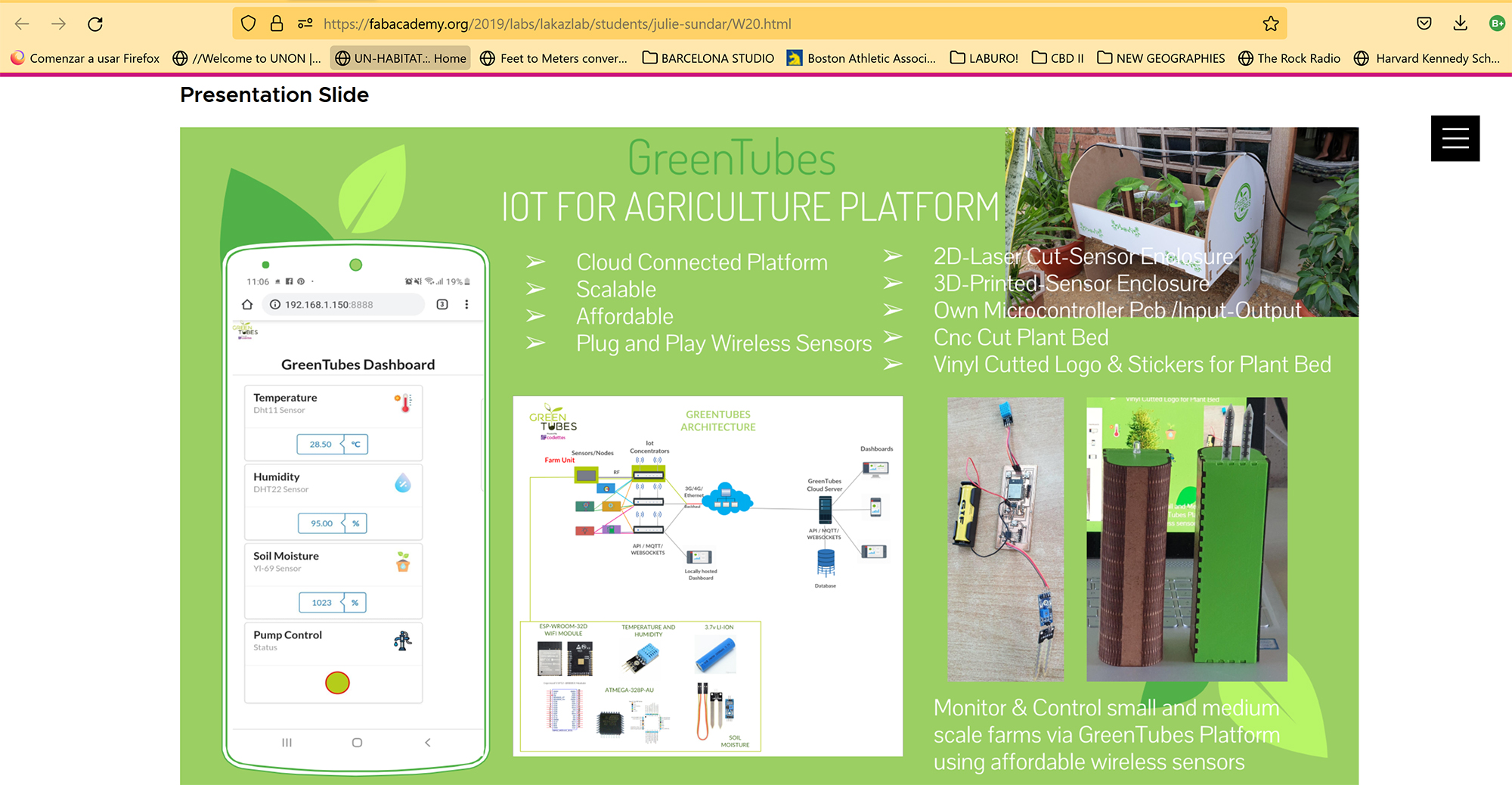
I have looked for precedents in the works of fellow fabbers.
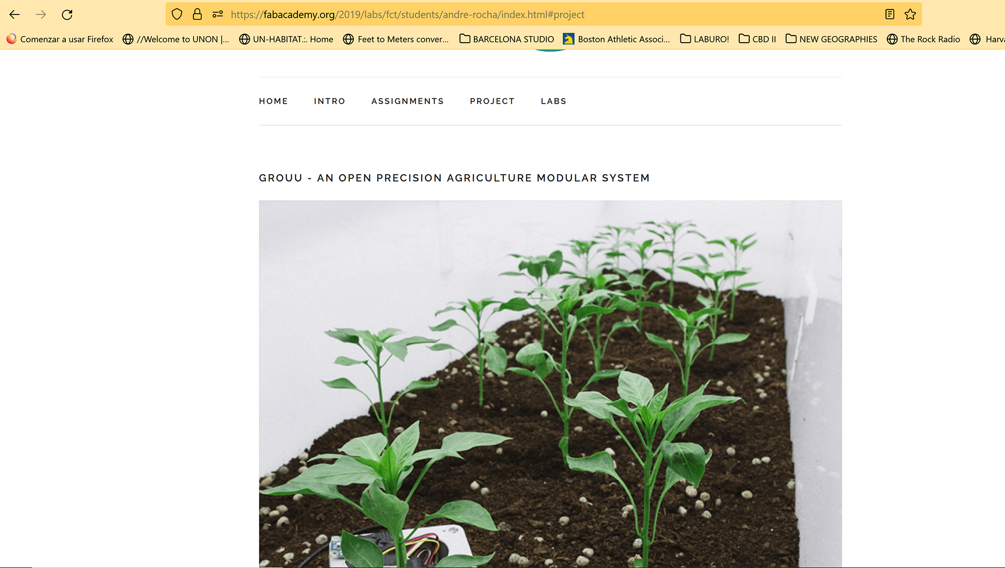
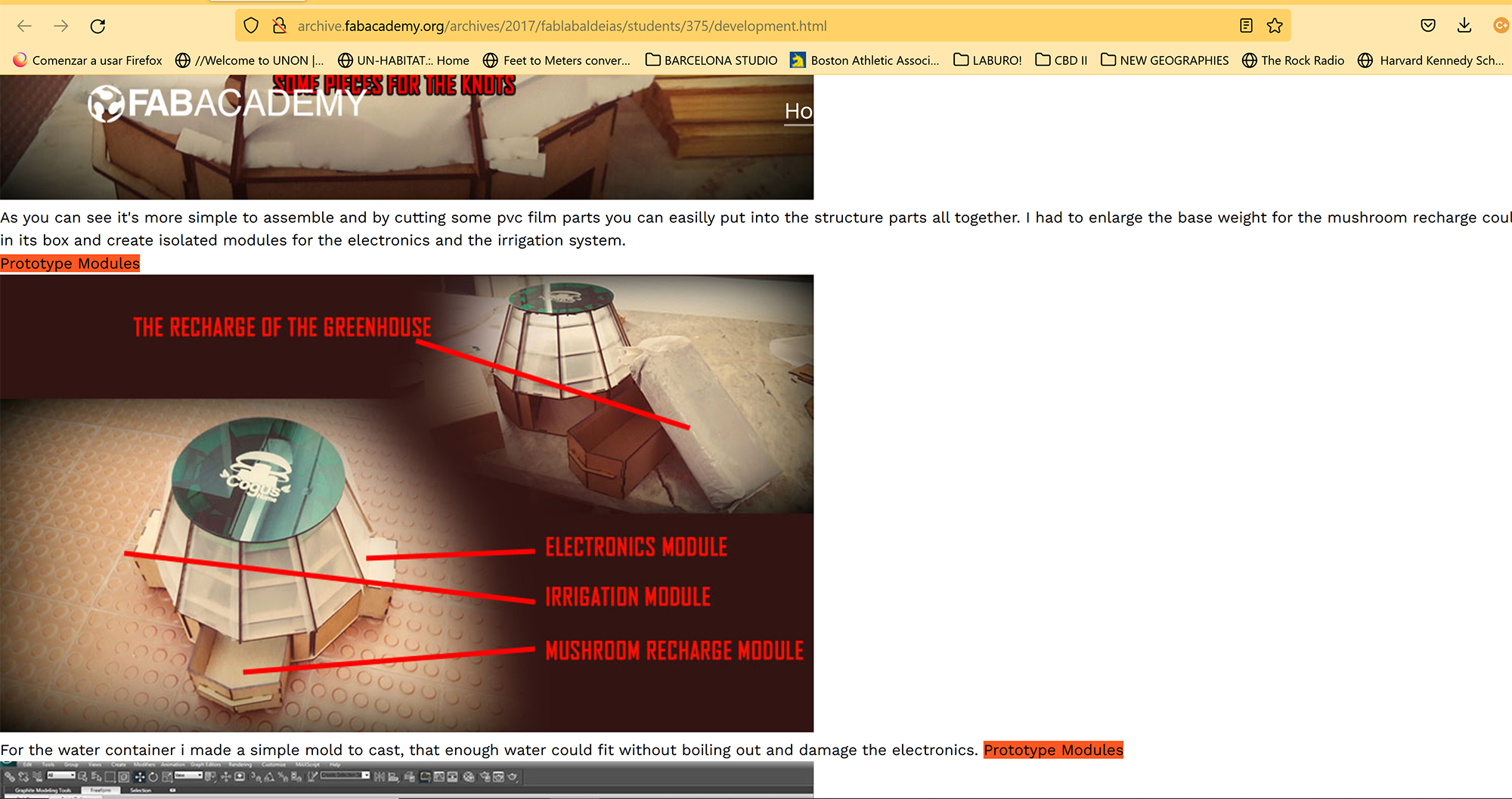
Green Tubes - Julie Sundar (2019)
What did you design?
I developed the design in three categories:
- Object Design:
In this category I designed the vertical cylindrical structure which is the basic framework of shadowhouse. I developed the conceptual drawings by hand and then the detailed design was developed in Fusion.
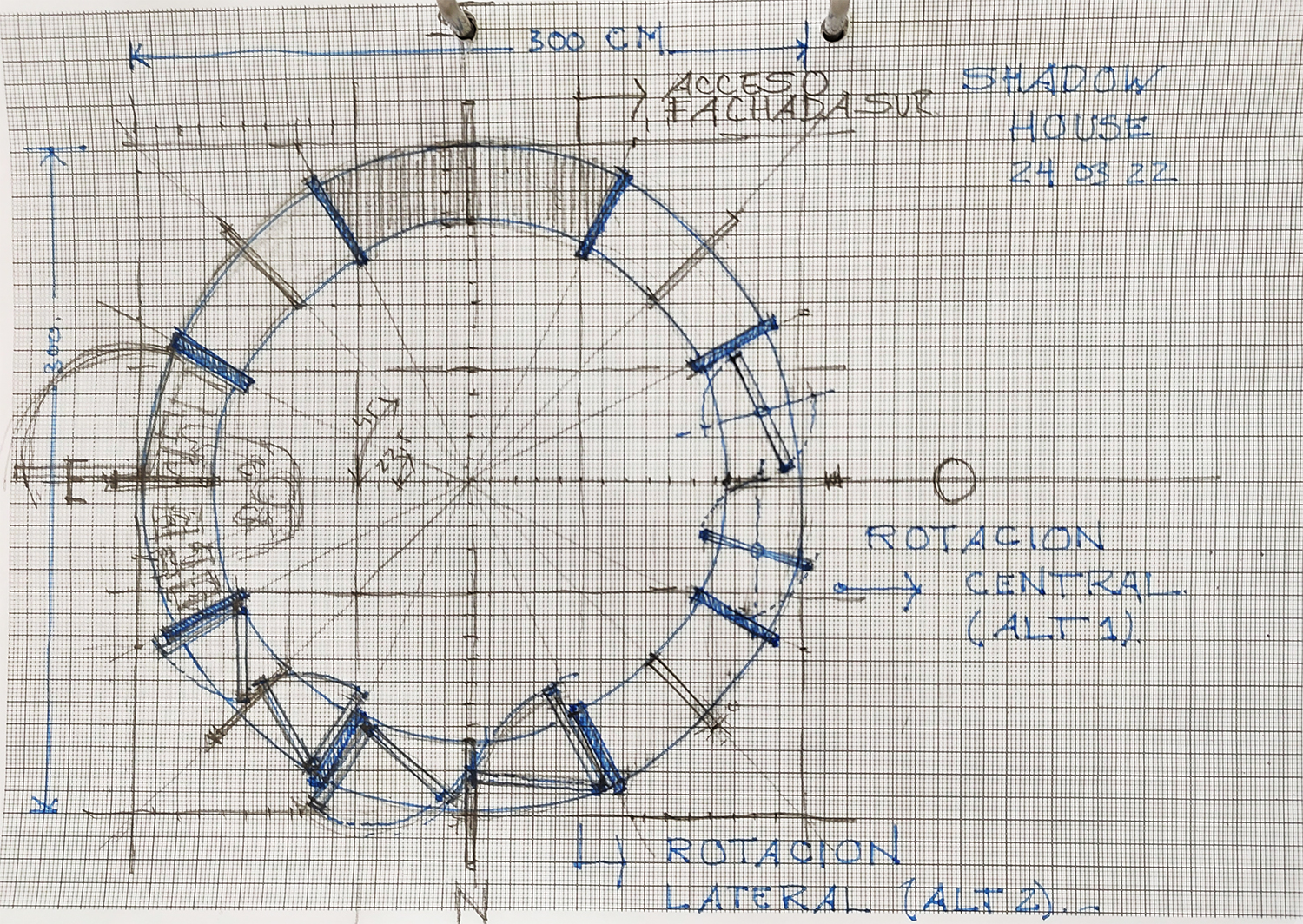
Image: Draft drawing, plan view
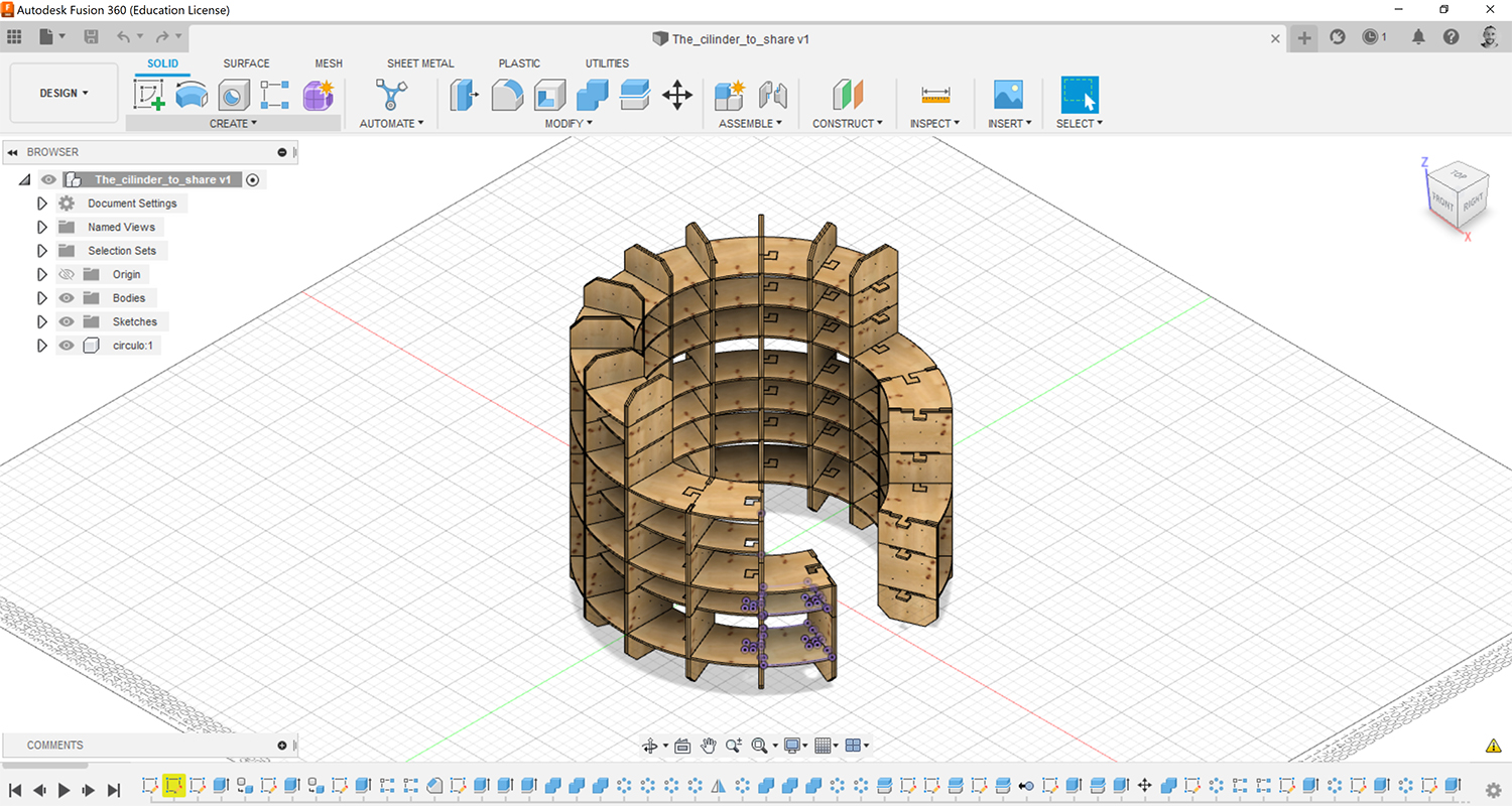
Image: Detailed drawing in Fusiongit
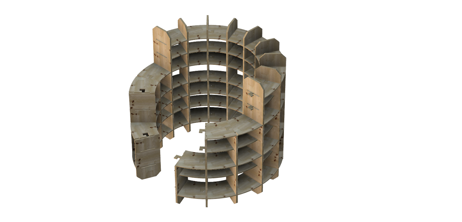
Image: Shadowhouse, render
- Mechanical Design:
In this category I designed all mobile parts and mechanisms. This includes the (i) holders for the servos, (ii) the holders for the bearings, (iii) the transitional pieces between servos and the blinds, (iv) transitional pieces between bearings and blinds (v) transmission rods and, (vi) the blinds.
I developed conceptual drawings by hand, and detailed drawings in Rhino and Fusion.
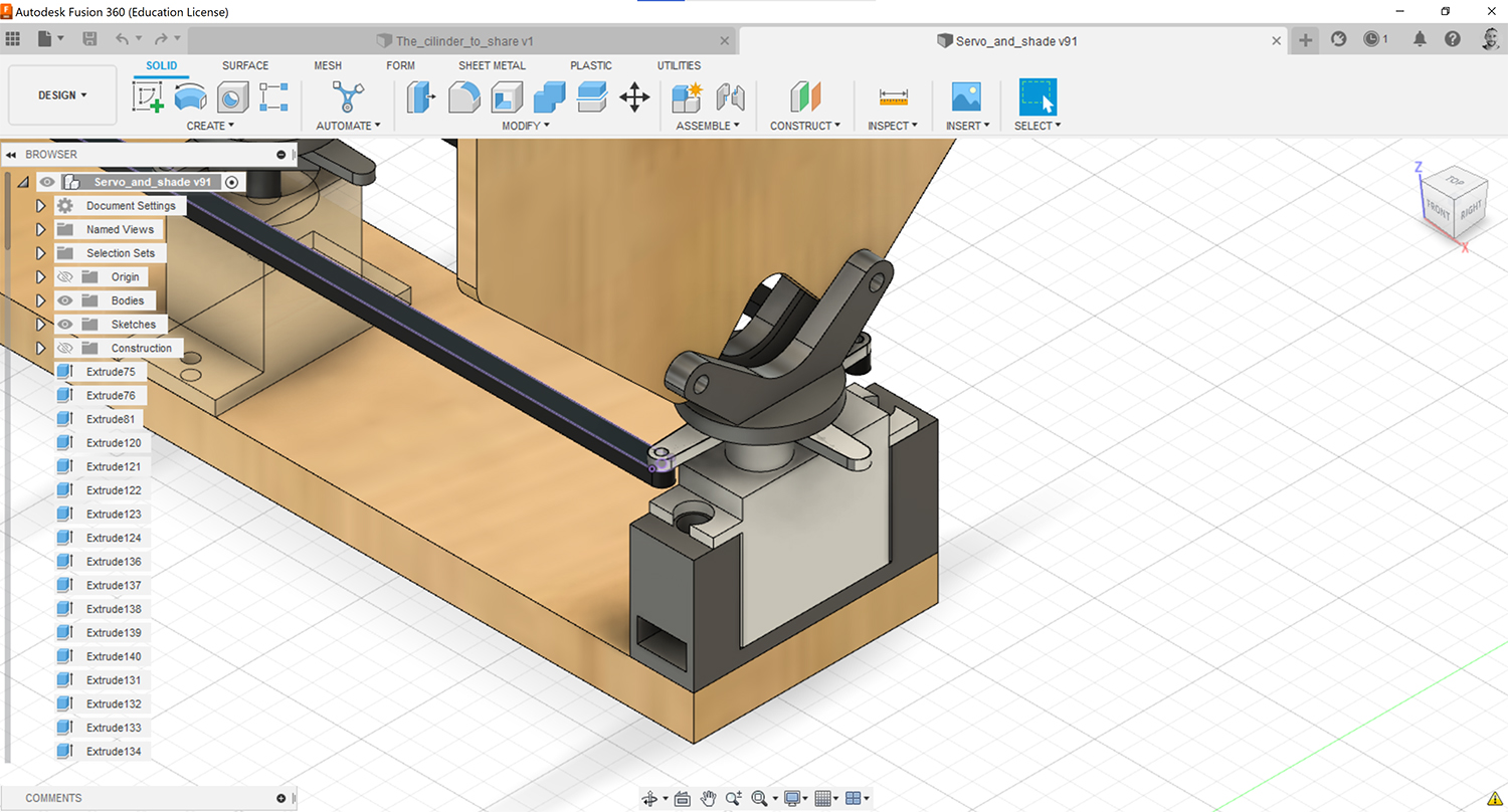
Image: (i) Holder for the servos
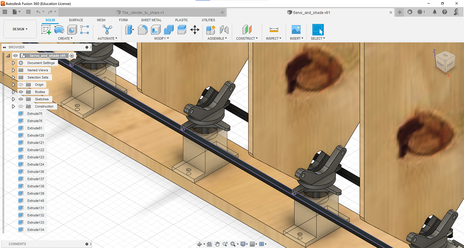
Image: (ii) Holder for the bearings
![]()
Image: (iii) Transition between Servo and Blinds
![]()
Image: (iv) Transition between bearing and Blinds
![]()
Image: (v) transmission rods
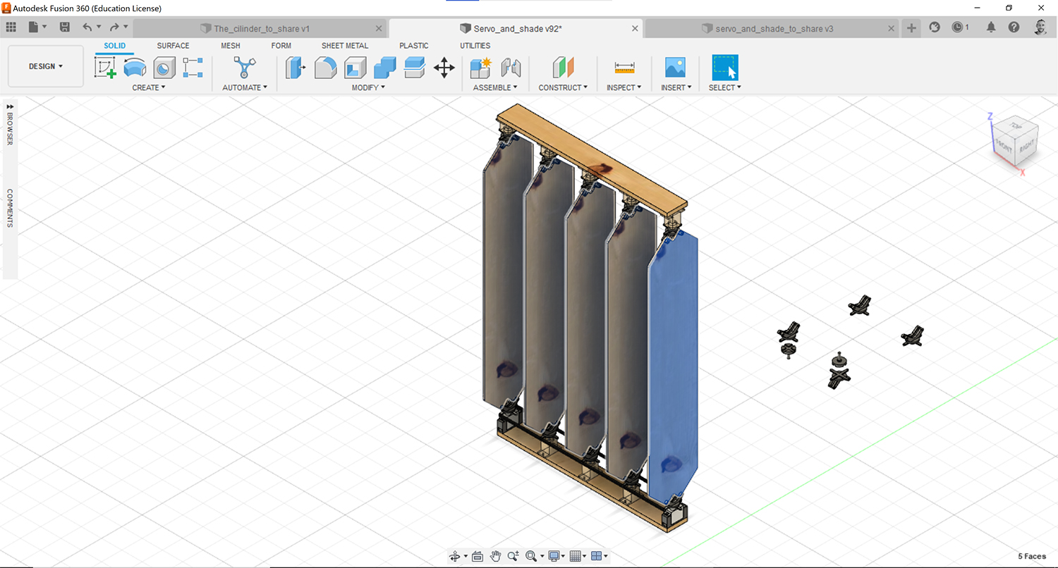
Image: (vi) Blinds
- Electronics Design:
I designed one customized PCB for the phototransistor.
![]()
Image: phototransistor PCB - Schematic in Eagle
![]()
Image: phototransistor PCB - Board in Eagle
Furthermore, I designed three customized PCBs for controlling motors:
- (i) to control servo motors
- (ii) to control stepper bipolar motors and
- (iii) to control a stepper unipolar motor.
These three PCBs are designed to allow for network operation. In this cycle of development I used the PCB that controls the servo motors and a pair of servo motors per module of the shadowhouse.
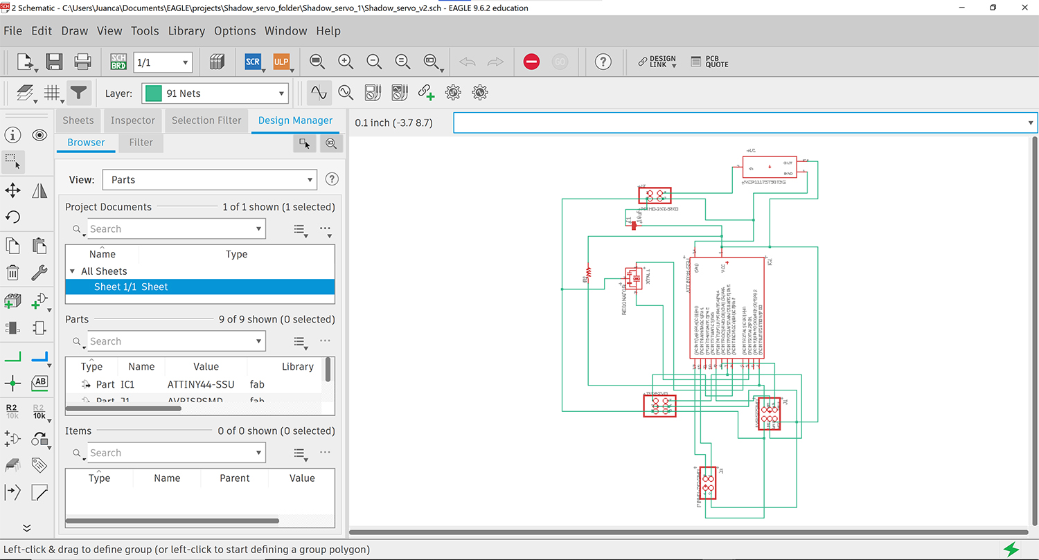
Image: (i) servo PCB - Schematic in Eagle
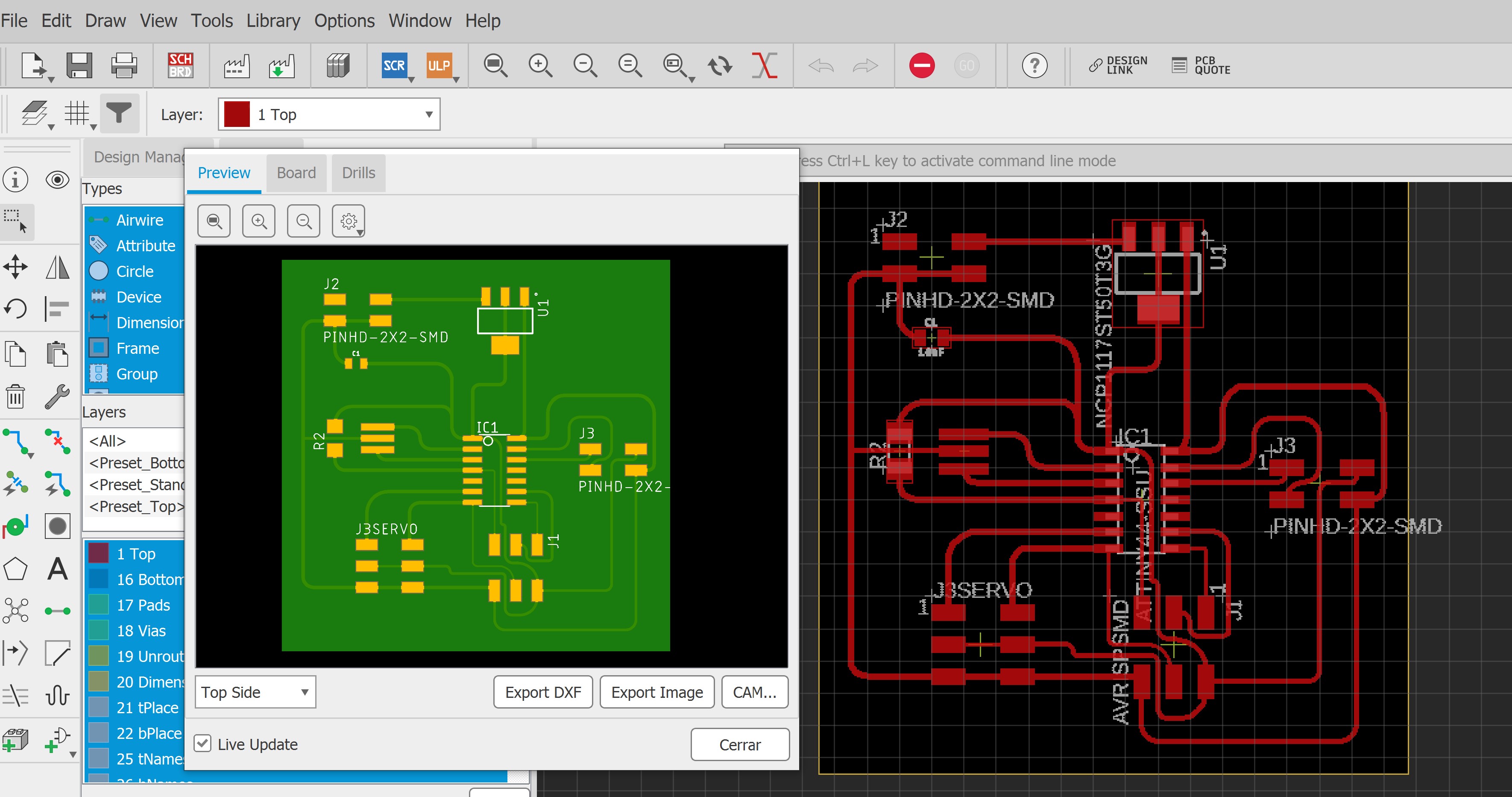
Image: (i) servo PCB - Board in Eagle
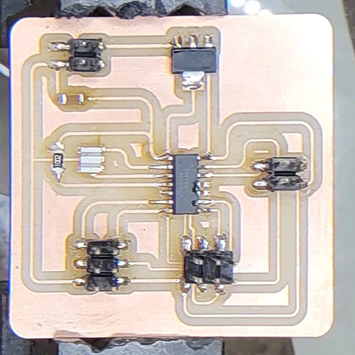
Image: (i) servo PCB - Assembled PCB
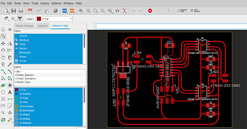
Image: (ii) stepper bipolar PCB - Board in Eagle
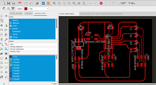
Image: (iii) stepper unipolar PCB - Board in Eagle
What materials and components were used?
- The cylinder of Shadowhouse: is made of 15 and 18 mm plywood boards cutted in the Shopbot Alpha.
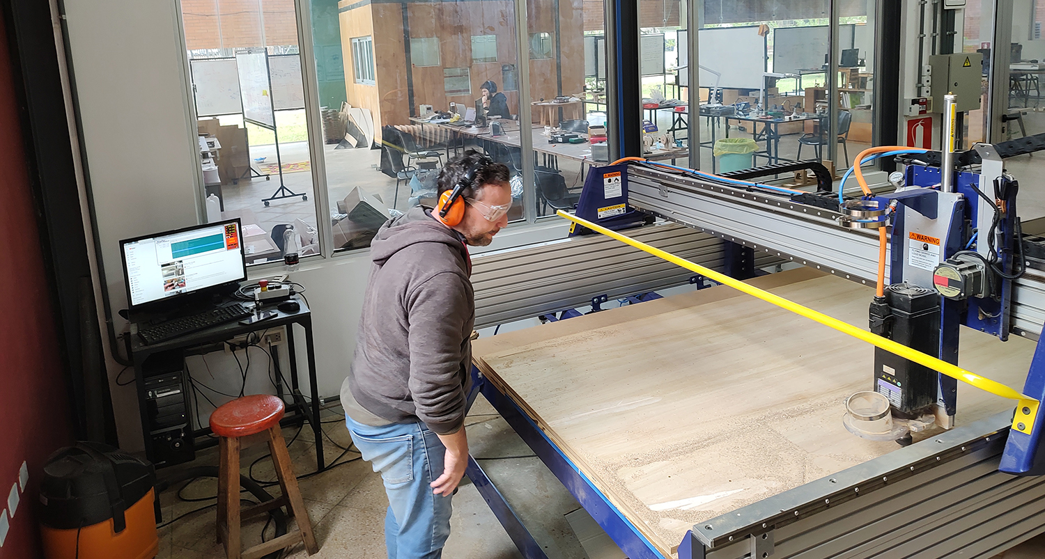
Image: cutting pieces at the Shopbot Alpha.
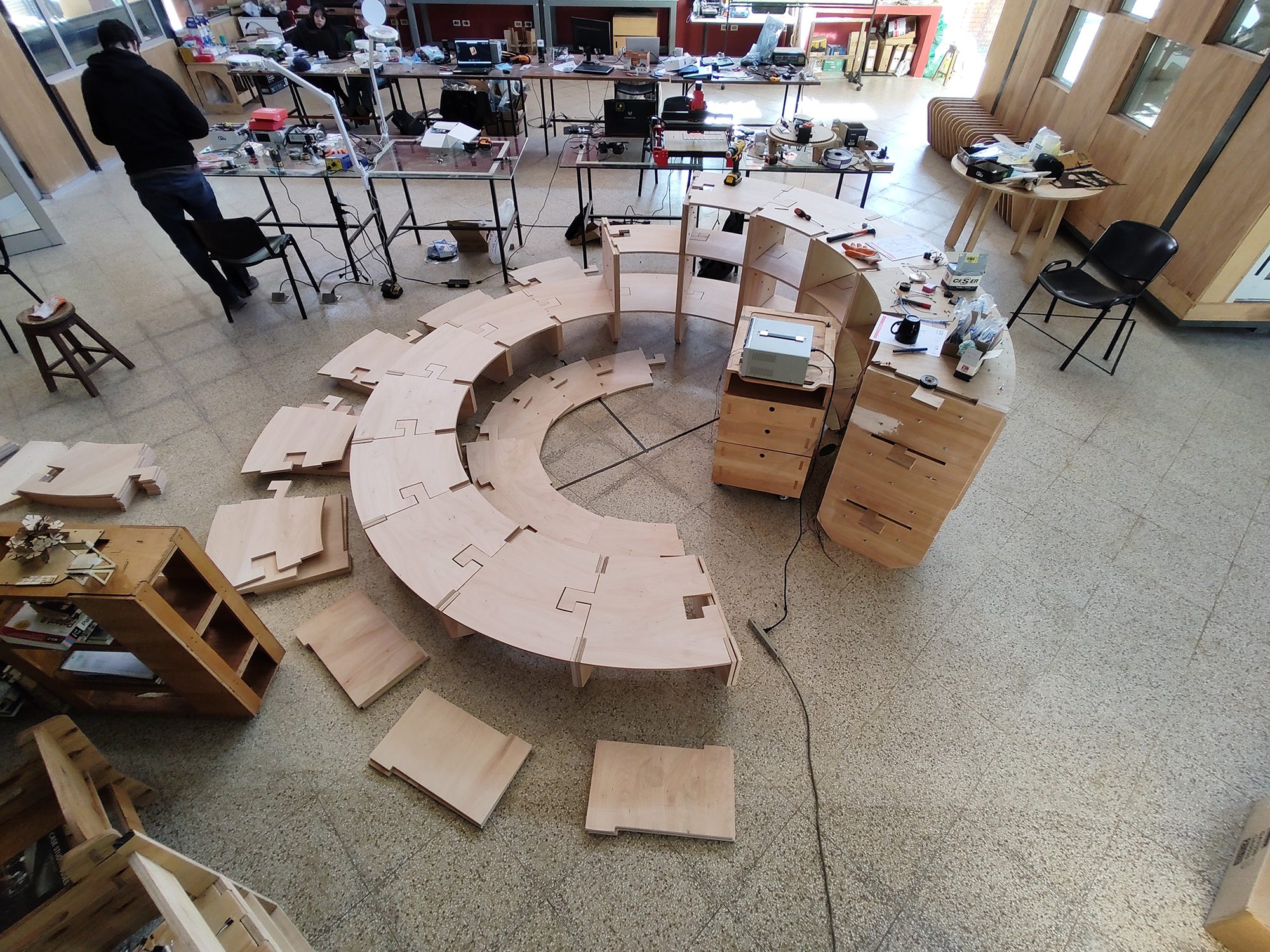
Image: plywood pieces ready to assemble.
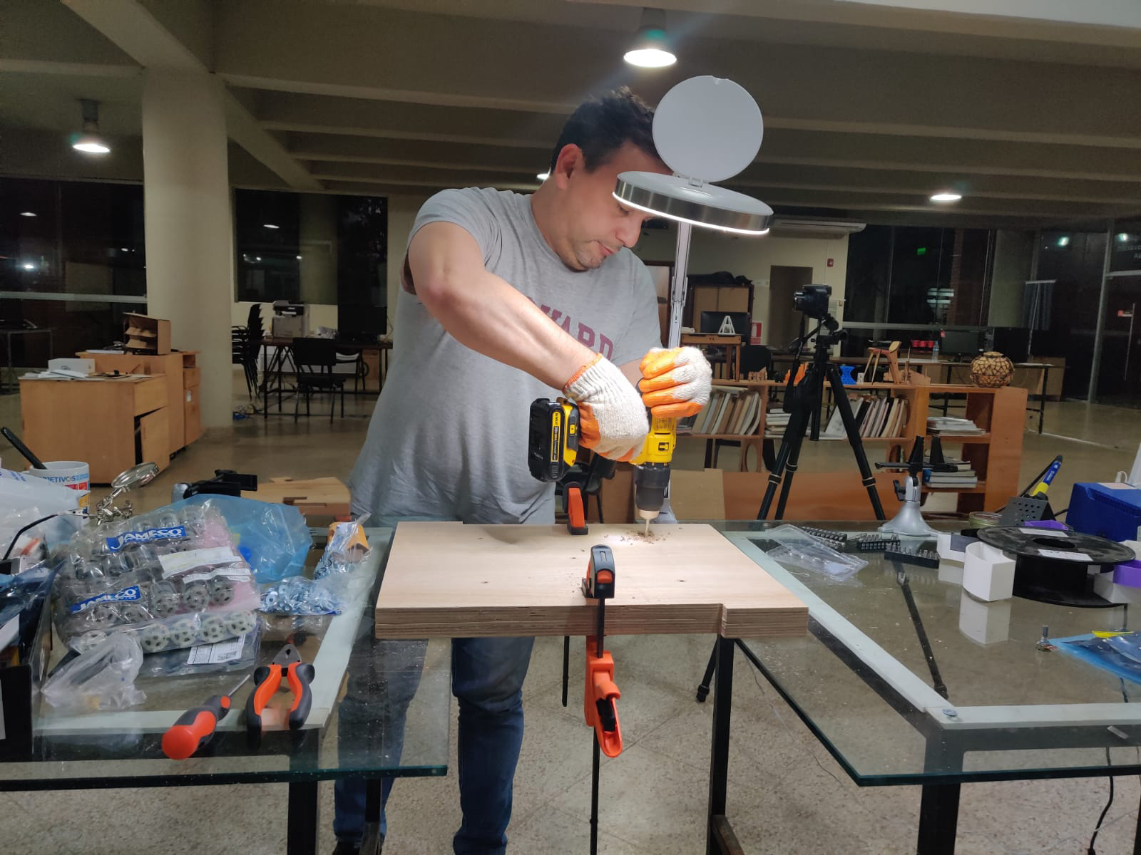
Image: assembly process.
- Holders for the servos: are 3d printed pieces in black PLA.
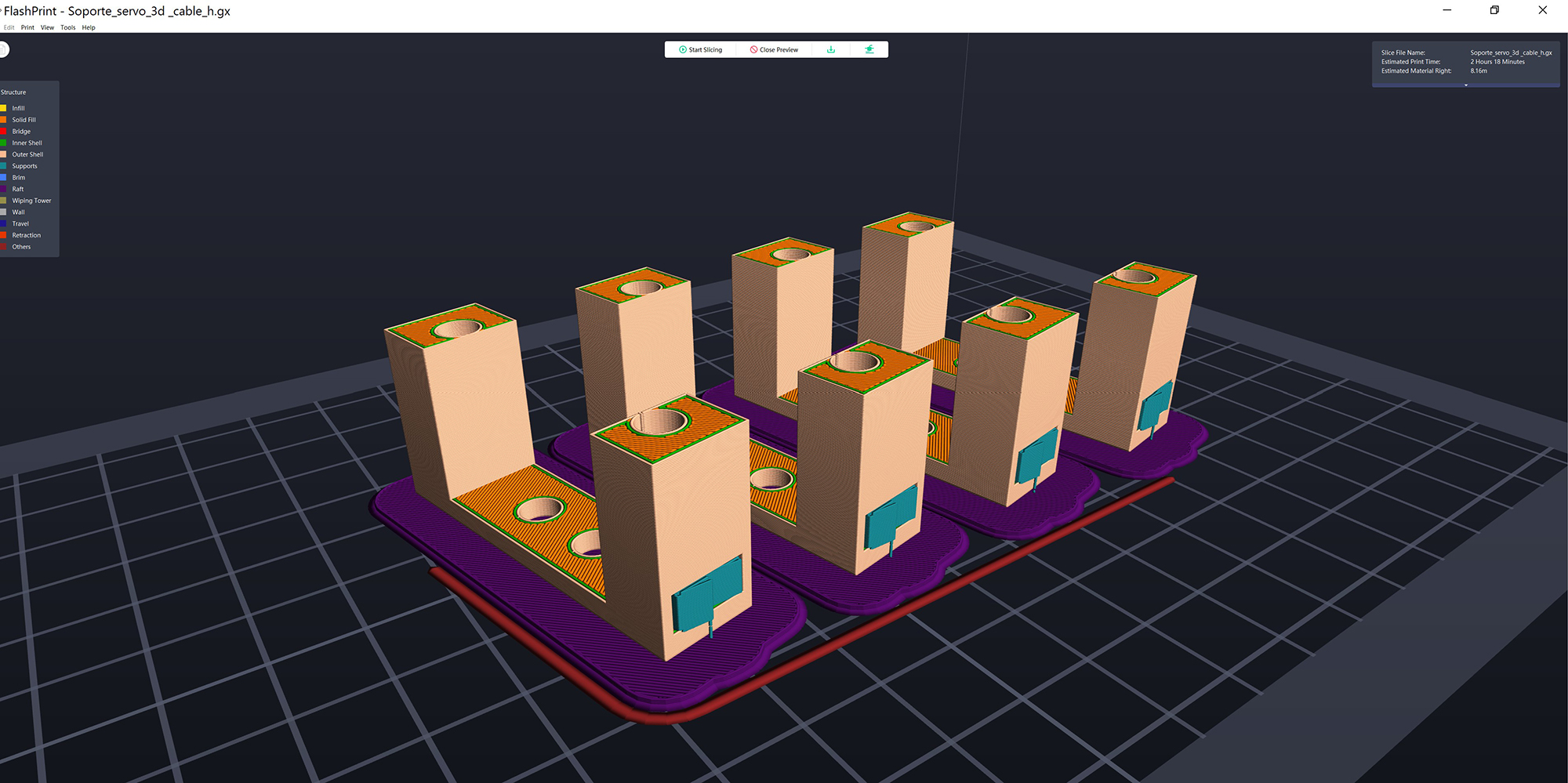
Image: 3d printing file - servo support
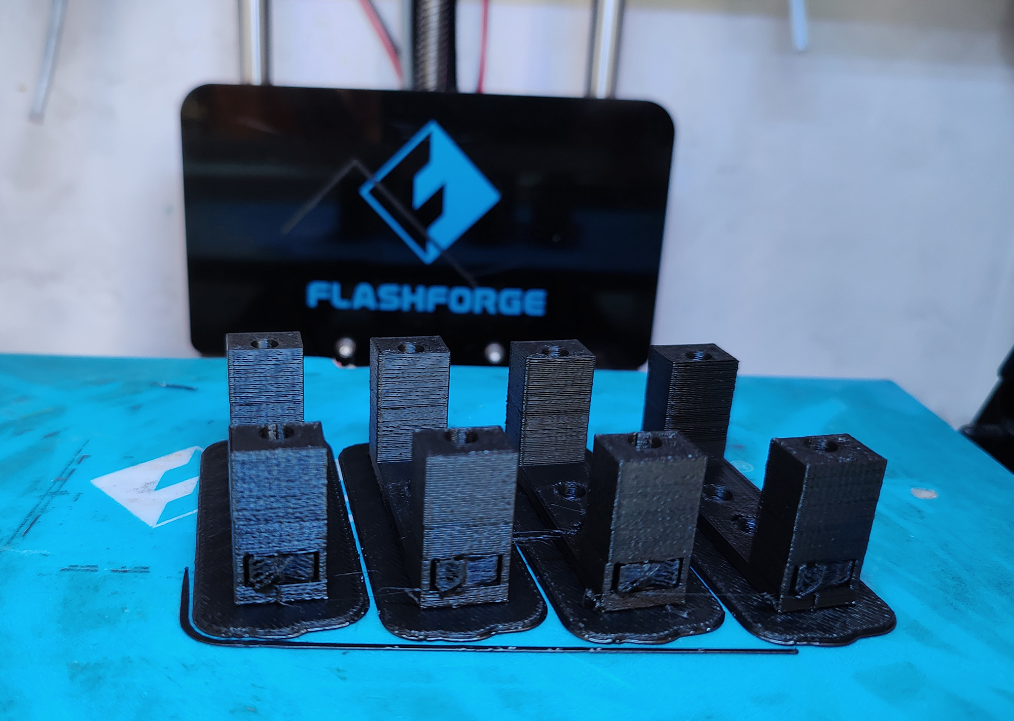
Image: 3d printed Servo support
- Holders for the bearings: are 3d printed pieces in black PLA.
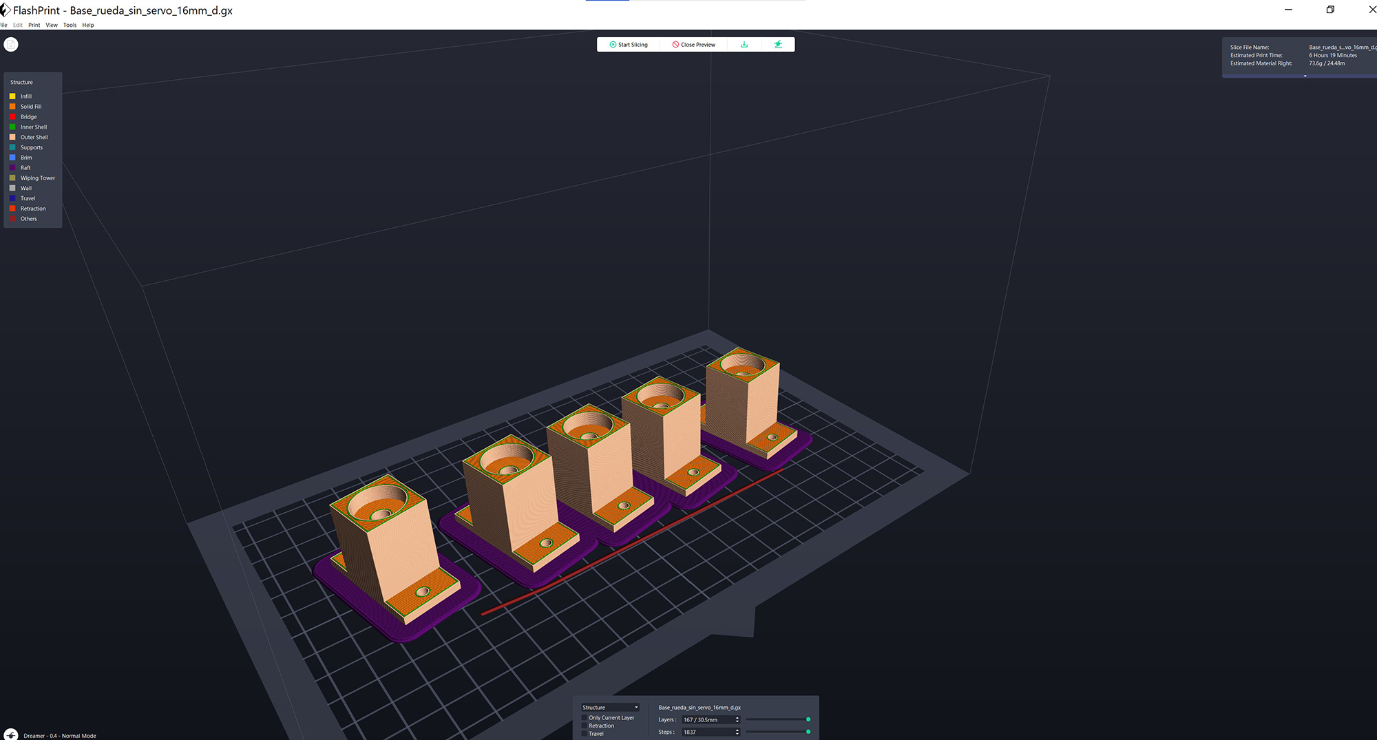
Image: 3d printing file - bearings support
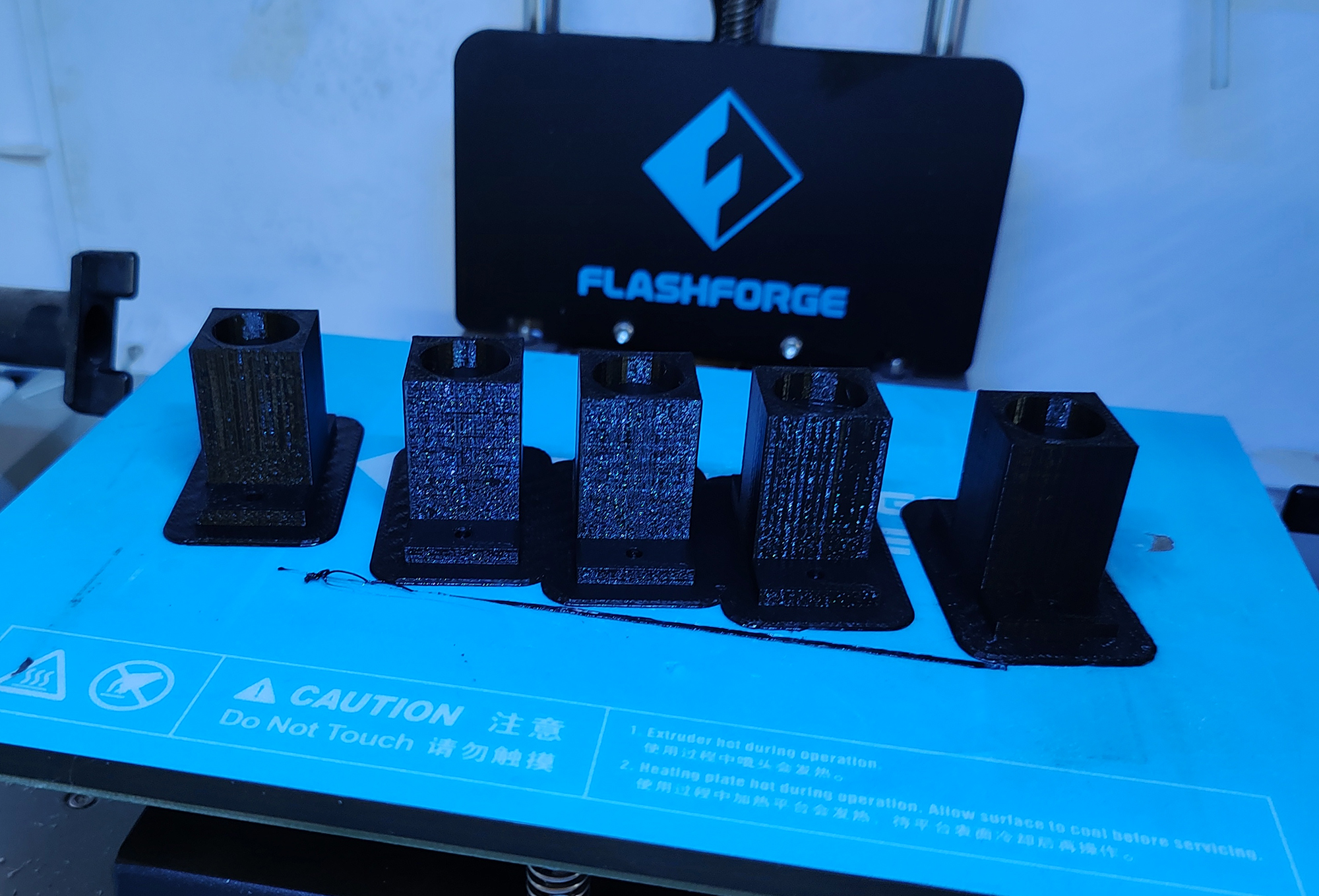
Image: 3d printed bearing support
- Transition pieces between servos and blinds: are 3d printed pieces in black PLA
![]()
Image: 3d printing file - transition piece between servos and blinds
![]()
Image: Installed transition piece between servos and blinds
- Transition pieces between bearings and blinds: are 3d printed pieces in black PLA
![]()
Image: 3d printed bearing transition axis
![]()
Image: Installed pieces between bearings and blinds
- Blinds are made of 9 mm MDF boards: cutted with the Lab’s laser cutter.
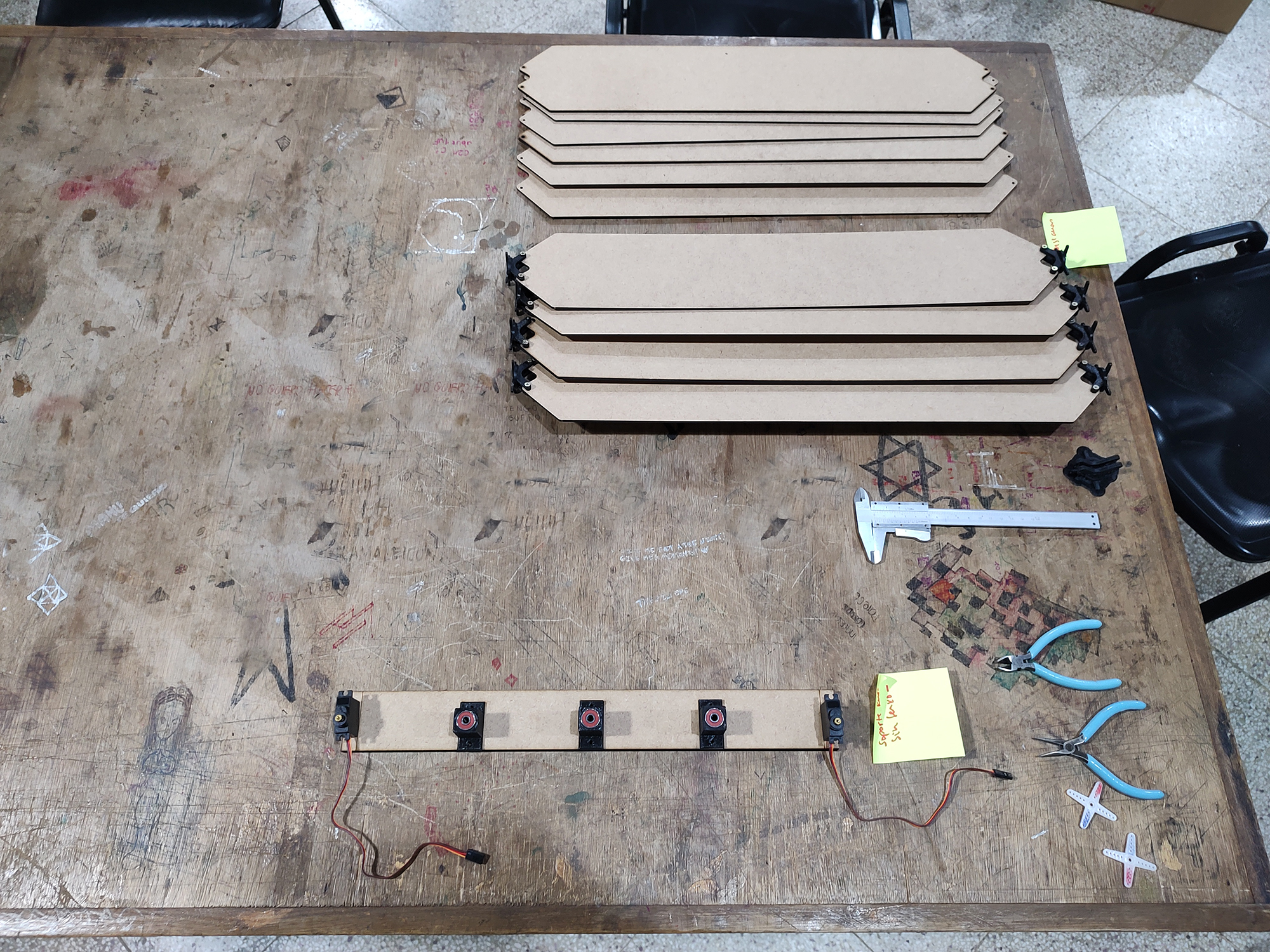
Image: lasser cutted blinds and 3d printed pieces, ready to assemble
- Transmission rods are made of acrylic: cutted with the Lab’s laser cutter.
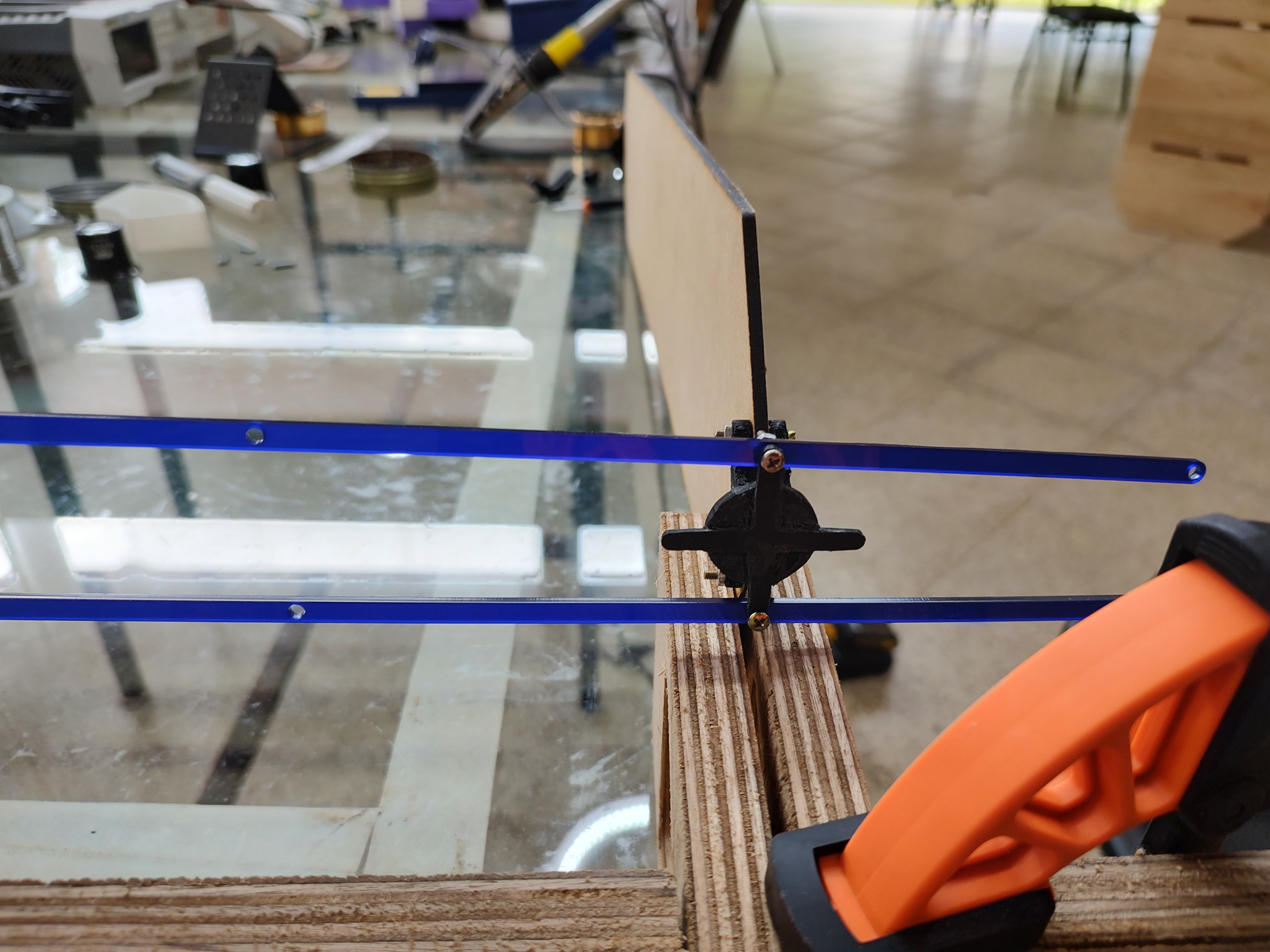
Image: lasser cutted acrilic rods
Where did they come from?
All materials come from the Lab’s inventory. The exceptions are small metal pieces, such as screws, bolts, nuts, washers and bearings. These pieces were bought in local hardware stores.
How much did they cost?
- Metallic parts (screws, bolts, nuts, washers and bearings): 150 US$.
- 3D printing filament: 30 US$.
- MDF Boards (9 mm, 15 mm and 18 mm) : 300 US$
- Electronic components: 20 US$
Total 500 US$
Costs refers only to materials. Machine time and labor costs are not included.
What parts and systems were made?
- Object Design:
All parts of the Cylinder were made in the lab using the CNC Shopbot Alpha.
- Mechanical Design:
All Blinds cutted in the JQ laser cutter .
Transmission rods which were cutted in the JQ laser cutter.
All transition pieces between bearings, servos and blinds, were made in the lab, using Flashforge Dreamer 3d printers.
- Electronics Design:
All PCBs were machined in the lab using the Roland MDX 540.
- Nework Design and programming:
Other than the three categories of design previously referred to, one major challenge for me, in terms of designing a system, was to design and program a functioning network. In Shadowhouse the network connects the Phototransistor PCB to the Servo controlling PCB, in order to regulate the movement of the servos. This network communicates through serial.
My full exploration went through the following stages:
1) Calibration of the servo motors: in order to know values of Pulse Width Modulation (PWM) - The objective is to determine values of PWM that correspond to three key positions of the servo: 0 degrees, 90 degrees and 180 degrees. This firmware will be applied to the “Servo controlling PCB” (based on the “Hello Servo PCB”)
2) Write and test a “Time signal” firmware: that transmits the states 0, 1, 2. These three states will later be related to positions 0 degrees, 90 degrees and 170 degrees. This time signal will be uploaded in the “Hello echo light button board”.
3) Write and test a firmware: that moves the servo to known PWM and positions, according to three States, following the table below:
| PWM | Angle | State |
|---|---|---|
| 6 | 0 | 0 |
| 22 | 90 | 1 |
| 36 | 170 | 2 |
This firmware will be based on serial communication, and on a first phase the states 0, 1, and 2 will be loaded manually on the monitor of Arduino IDE. This firmware will be applied to the “Servo controlling PCB” (based on the “Hello Servo PCB”)
4) Form a first network: linking the “Hello echo light button board” with the “Servo controlling PCB”. The servo will move periodically, to positions 0,1 and 2 according to the input received from the “Hello echo light button board”.
5) Develop a serial-based firmware for the “Light Sensor PCB”: the phototransistor produces an analog signal from 0 to 1024. This range will be initially divided also in three states of 0, 1 and 2.
| Analog Signal from phototransistor | Observation: | state | angle |
|---|---|---|---|
| 0 - 340 | More light, lower the number | 0 | 0 |
| 341 - 682 | 1 | 90 | |
| 683 - 1024 | Less light, higher the number | 2 | 170 |
6) Form a second network, linking the “Light Sensor PCB” with the “Servo Controlling PCB”: The servo will move inversely in reference to light levels. More light, the servo will go to “Closed” position (170 degrees) and with less light, the servo will go to “Open” or “Full Open” (90 degrees and 0 degrees, respectivelly). This is the basic network necessary for my final project.
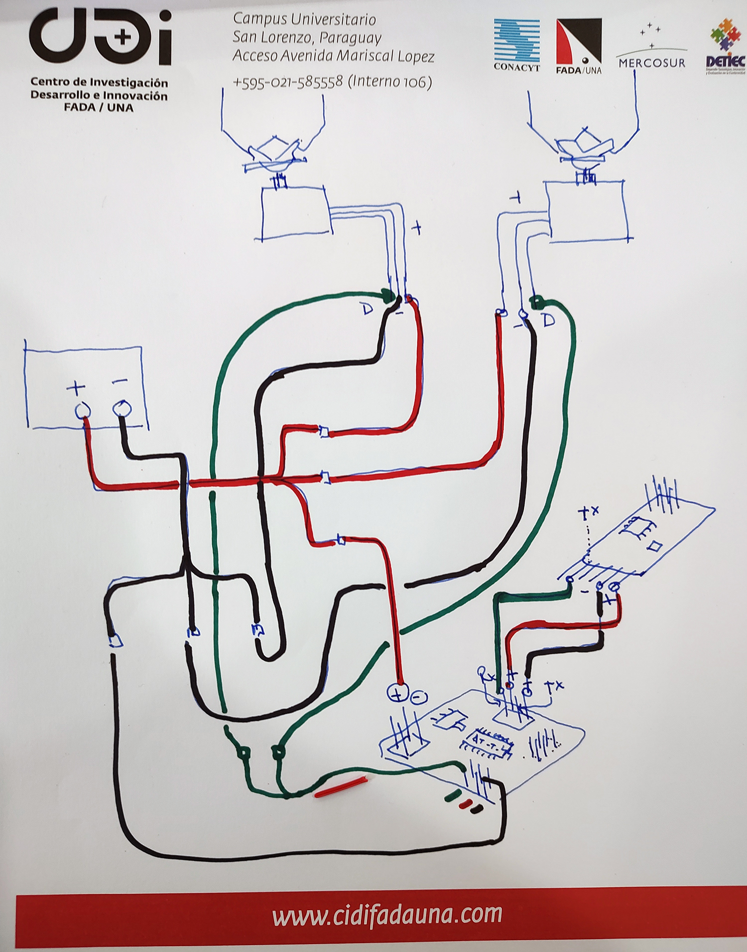
Image: Network conceptual diagram
![]()
Image: Yodaboard programming the phototransistor PCB
Video: Network - Phototransistor PCB, Servo PCB and Servos
Video: Assembly test Network - Phototransistor PCB, Servo PCB and Servos
7) Final adjusted code: Once all pieces were assembled in place, I adjusted the program to the final light levels and angular positions.
- You can see the final adjusted code used in the Phototransistor PCB below:
// This example code is in the public domain

#include <SoftwareSerial.h>

int rx = 0;    //Declares the RX 1 pin 3
int tx = 2;    //Declares the TX to be PB2
int sensorPin = A3; // Declares input sensor
int sensorValue;
int limitOne = 204;
int limitTwo = 409;
int limitThree = 612;
int limitFour = 816;


SoftwareSerial mySerial(rx, tx);  //Setting up the RX/TX pins as a SoftwareSerial


void setup() {

mySerial.begin(4800);

}

void loop() {

  sensorValue = analogRead(sensorPin);

  if (sensorValue <=limitOne){
    mySerial.println('4');
  }
  else if (sensorValue >limitOne && sensorValue <=limitTwo){
     mySerial.println('3');
  }
  else if (sensorValue >limitTwo && sensorValue <=limitThree){
    mySerial.println('2');
  }
  else if (sensorValue >limitThree && sensorValue <=limitFour){
    mySerial.println('1');
  }
  else if (sensorValue >limitFour){
    mySerial.println('0');

  }


  delay(1000);

}

// reference : https://www.arduino.cc/en/Tutorial/AnalogReadSerial
- You can see the final adjusted code used to control the servos in Shadowhouse below:
#include <SoftwareSerial.h>

int rx = 1;    //Declares the RX 1 pin 3
int tx = 0;    //Declares the TX 2 pin 4

SoftwareSerial mySerial(rx, tx);  //Setting up the RX/TX pins as a SoftwareSerial

char buttonState = '0';//Declares the character that represents the virtual button current state
char lastButtonState = '0'; //Declares the character that represents the virtual button last state

int servoPin = 6;     //Declares the pin where the Servo is already attached
int servoPinb = 7;     //Declares the pin where the Servo is already attached
int dutycycle = 6;
int dutycycleb = 6;
void setup(){
  mySerial.begin(4800);       //Start the serial communication and select the its speed that deppends of the frequency that it will be program the attiny

  pinMode(servoPin, OUTPUT);      //Configures the LED pin as an output
  pinMode(servoPinb, OUTPUT);      //Configures the LED pin as an output


}

void loop() {
 // mySerial.println("probando");

  buttonState = mySerial.read();    //Reads the message from the command line

  if (buttonState != lastButtonState) {   //Checks if there exist a change in the virtual button state

    if (buttonState == '0') {         // Condition For Motor Minimum light full open

    mySerial.println("Servo IS 90 deg \r");         //Prints in the screen the actual state
    dutycycle = 6;
    dutycycleb = 6;
     }
    else if (buttonState == '1'){      // Condition More light closing

    mySerial.println("Servo IS 105 deg \r");         //Prints in the screen the actual state
    dutycycle = 12;
    dutycycleb = 12;
    }
    else if (buttonState == '2'){      // Condition More light closing

    mySerial.println("Servo IS 120 deg \r");         //Prints in the screen the actual state
    dutycycle = 17;
    dutycycleb = 17;
    }
    else if (buttonState == '3'){     // Condition More light closing

    mySerial.println("Servo IS 135 deg \r");         //Prints in the screen the actual state
    dutycycle = 8;
    dutycycleb = 8;
    }
    else if (buttonState == '4'){     //  Condition Full closed

    mySerial.println("Servo IS 150 deg\r");          //Prints in the screen the actual state
    dutycycle = 25;
    dutycycleb =25;
    }

    analogWrite(servoPin, dutycycle);     //Activates Servo according to PWM
    analogWrite(servoPinb, dutycycleb);     //Activates Servo according to PWM

  }

  lastButtonState = buttonState;        //Sets the current state as a last state

}
What processes were used?
- Object design and mechanical design using 2d and 3d CAD.
- 3D Printing. (additive)
- CNC Cutting. (subtractive)
- Laser Cutting. (subtractive)
- Electronics Design.
- Networking and communication (using serial).
What questions were answered?
- In this cycle of development:
Can I actually assemble everything and make it work?
¡Yes! everything fitted in and the full system works. Shadowhouse is responsive and opens and closes the blinds inversely in relation to light levels.
Can I obtain all required parts in the lab and the local market?
Yes, we could find all the required parts in the lab’s inventory and in local hardware stores. This is very important in terms of being able to produce and then maintain a relatively robust and inexpensive system.
- In a future cycle of development (working with farmer’s cooperatives, after Fab Academy)
Will this be a contribution for farmers?
This requires further testing, thinking, discussion and feedback from farmers. I like the notion of the vertical cylinder, in which each “vertical group” of modules has a different orientation, and thus, moves differently. In the diagram below you can see that we can form 8 “vertical groups” according to the orientation toward the cardinal points.
I believe this is a very poetic image, but we will have to test it more to see if it actually has practical value.
What can be improved in the design with the orientation of the farmers?
I want to keep on working on other systems, with the help and co-design of farmers: irrigation and water recirculation would be the next system to develop. My intention is to follow this efforts working alongside the national Federation of Production Cooperatives (FECOPROD).

Image: Signature of a Memorandum of Understanding between the University and the Federation of Production Cooperatives (FECOPROD)
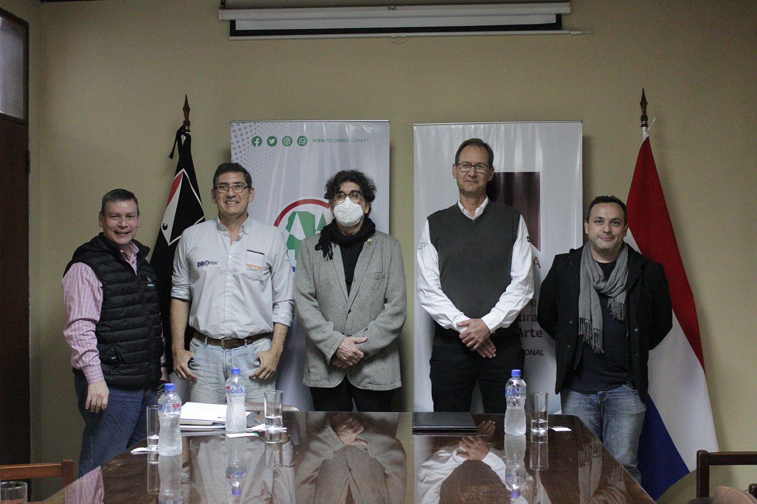
Image: Staff of FADA UNA and of the Federation of Production Cooperatives (FECOPROD)
What worked? What didn’t?
Well, everything, after many, many attempts. But I could not develop many alternatives and options that I am still interested in, such as:
- Can I control several vertical levels of blinds with a single stepper engine?
- Can I explore other materials for the blinds? Such as acrylic? or textiles in a rigid framework?
How was it evaluated?
- In this cycle of development:
I could complete and document a fully functioning prototype of the Shadowhouse.
- In the next cycle of development:
We are starting a joint effort with farmers cooperatives to improve the project or extract applicable lessons from it and use those findings in other similar projects oriented to improve farming.
Please see the results of my Fab Academy Journey below:
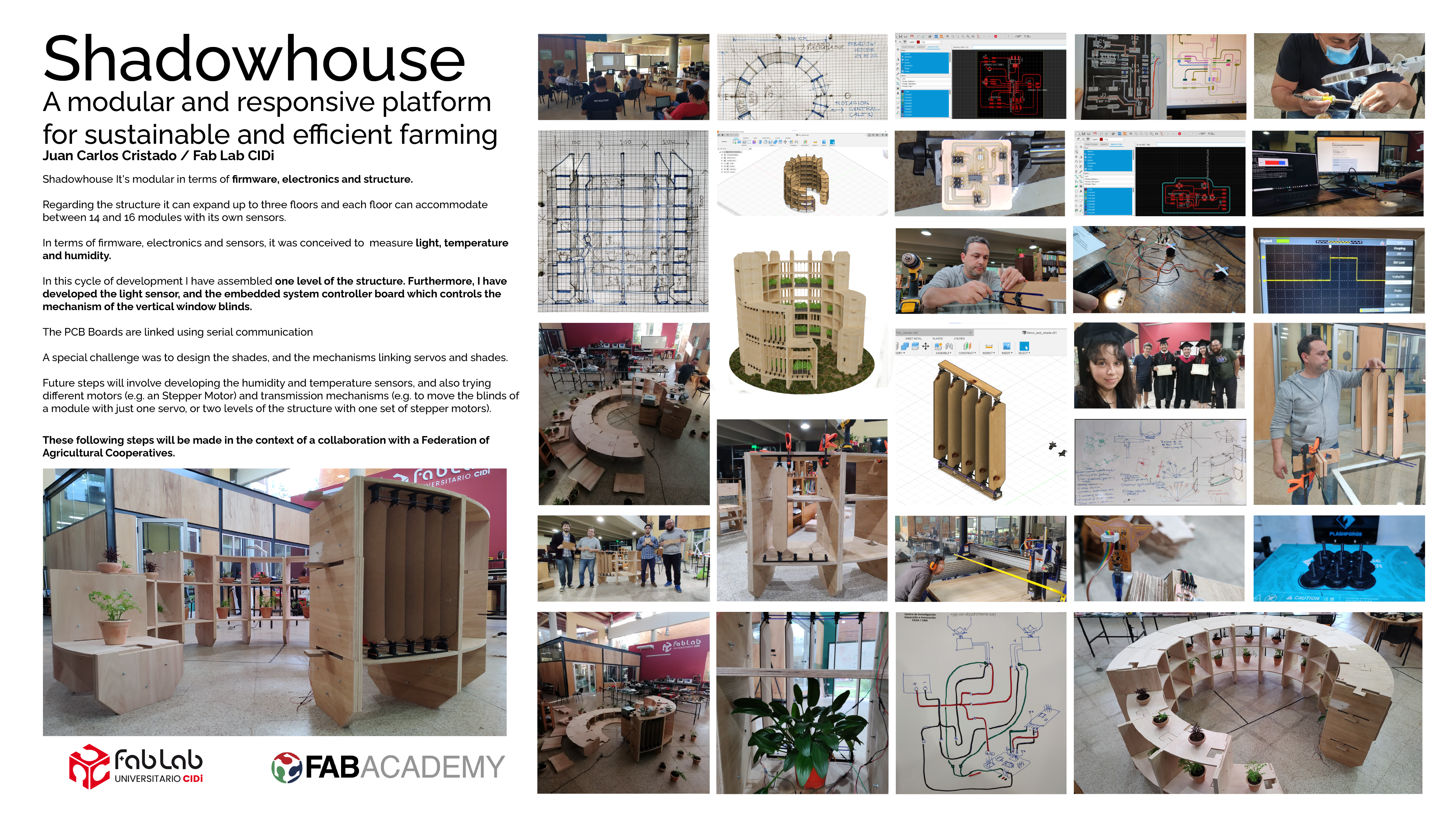
Image: Final presentation board
Please find the fabrication files here:
Object Design:
DXF file - nesting circle pieces - for CNC cutting
DXF file - nesting feet pieces - for CNC cutting
Mechanical Design:
DXF File - Blinds - for laser cutter
DXF File - Transmission rods - for laser cutter
DXF File - Base template for servo holders and bearing holders (up) - for laser cutter
DXF File - Base template for servo holders and bearing holders (down) - for laser cutter
STL File - Holder for Servo - for 3D printing
STL File - Holder for Bearing - for 3D printing
STL File - Axis for Bearing - for 3D printing
STL File - V transition piece over bearing - for 3D printing
STL File - V transition piece over servo - for 3D printing
Electronics Design:
Phototransistor PCB:
Shadow Servo:
Creative Commons License:
Shadowhouse © 2022 by Juan Carlos Cristaldo Moniz de Aragao is licensed under CC BY-NC-SA 4.0