8. Computer controlled machining
Week 07 / March 09
This week’s assignment:
Group assignment:
- do your lab’s safety training
- test runout, alignment, fixturing, speeds, feeds, materials, and toolpaths for your machine
Individual assignment:
- make (design+mill+assemble) something big (~meter-scale)
- extra credit: don’t use fasteners or glue
- extra credit: include curved surfaces
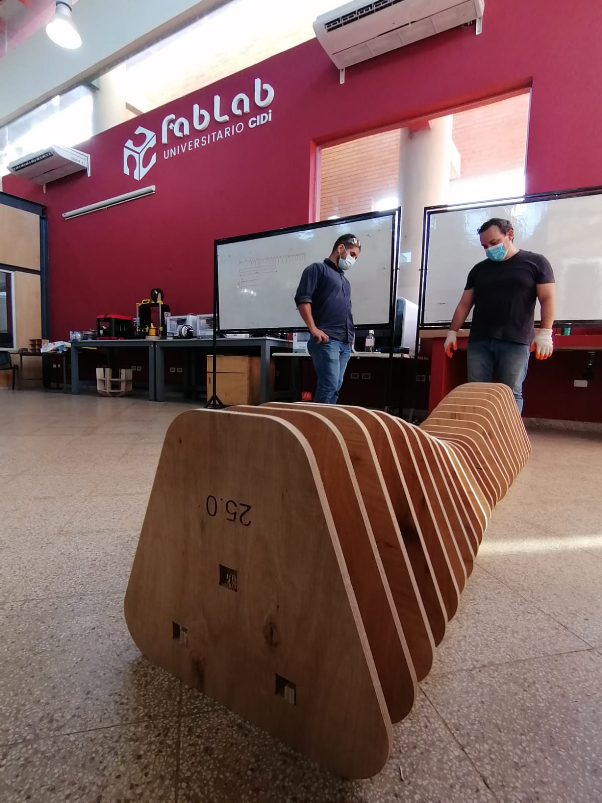
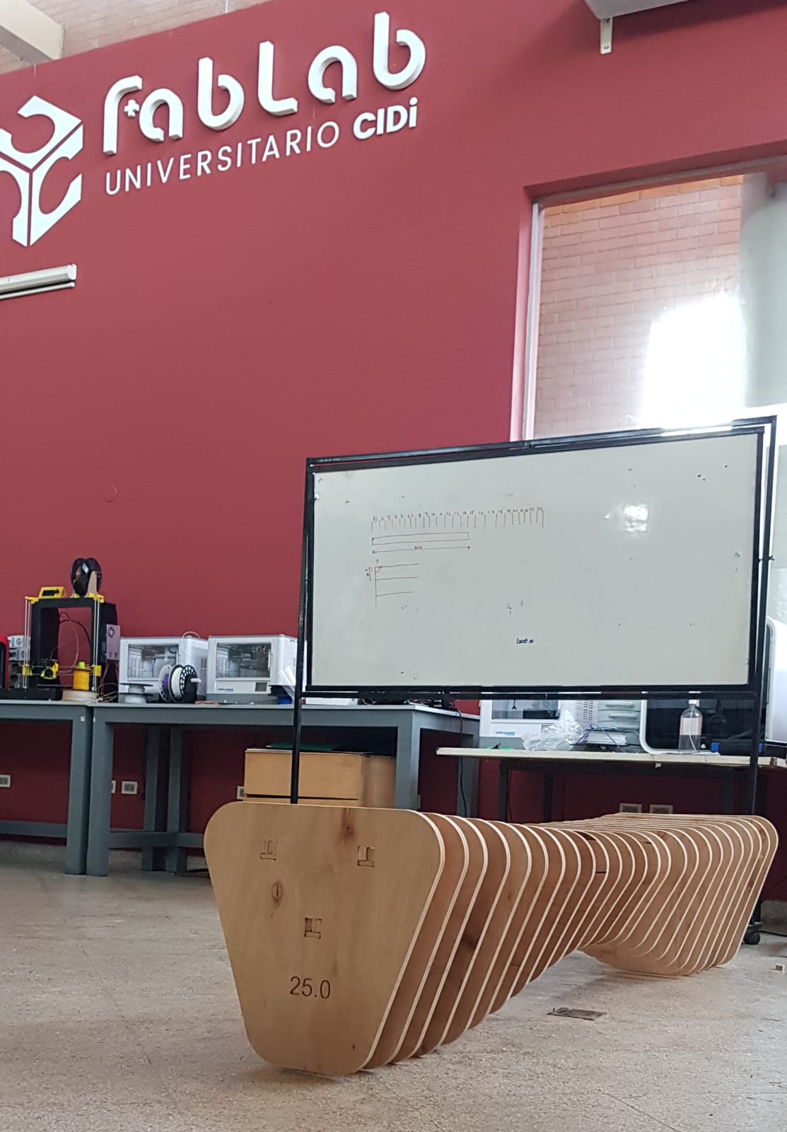
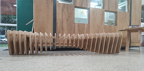
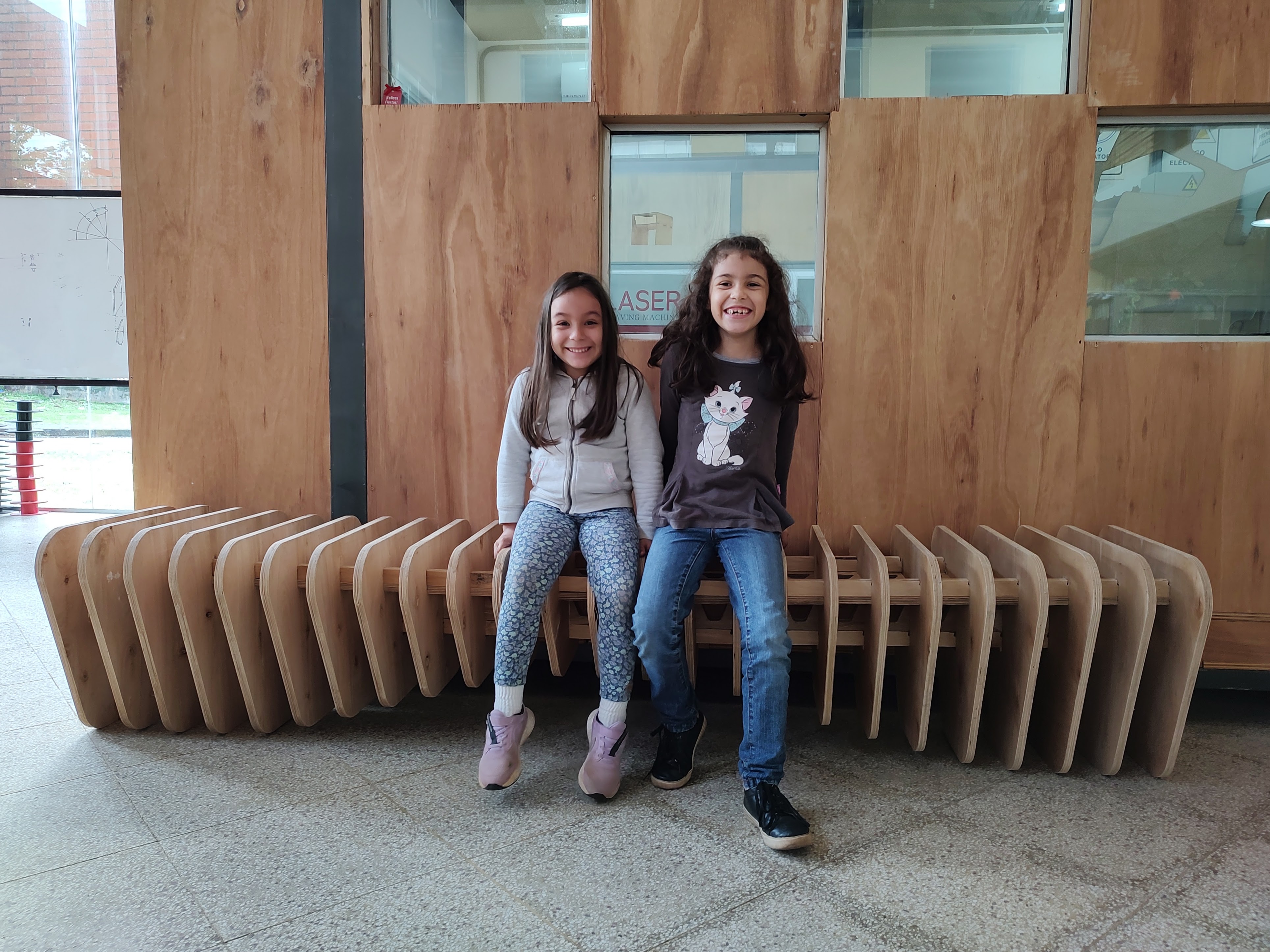
For this week’s exercise we received the instruction of “building something big”. I designed and built a parametric bench (2,40 meters long).
Research
Parametric Design
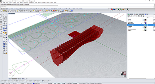
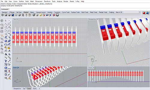
As a design tool, I used Rhino and Grasshopper. As a reference I followed this tutorial
It is a very interesting and complete material, and helped me a lot in the following aspects of the process.
- modeling a relatively free form and transform it dynamically using the Gumball
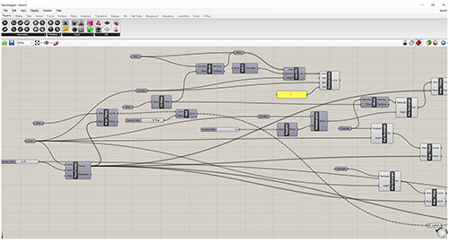
- slice it using grasshopper.
- being able to nest the slices, reorienting to a desired plane (the ground) and name the pieces to facilitate assembly.
This is really a great learning process because now I can “slice” any complex geometry and I also know how to designate the pieces to assemble. Thus very complex geometries become like a large 1 to 1 assembly model.
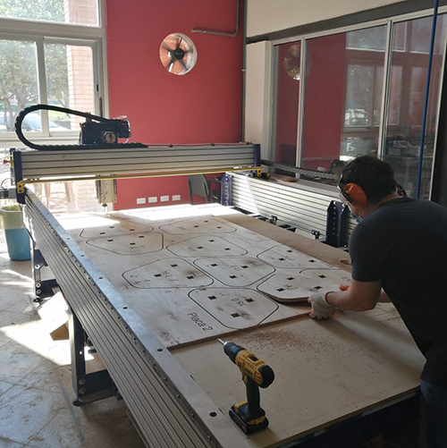
Fabrication of the Model
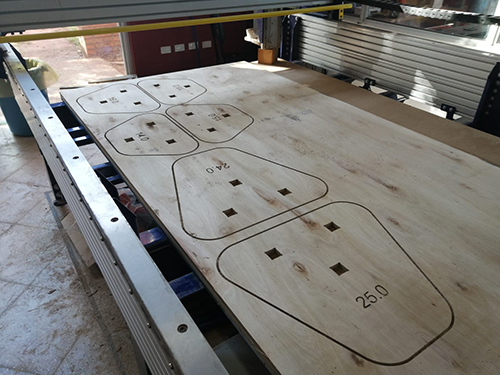
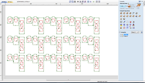
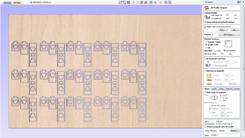
The fabrication process on the CNC was pretty much straightforward and uneventful. We have a Shopbot alpha at the lab. For preparing the fabrication files I “baked” the grasshopper files and then exported everything as a DXF file, in millimeters. All generated slices were nested according to stock size (2440 x 1220 mm). We used 13 mm plywood. For the fabrication process we used two different programs: Vcarve Pro 11, and Shopbot 3.
The inner square holes in the slices were cutted “inside”, with T bone corners. The outline of the slices was cutted “outside”.
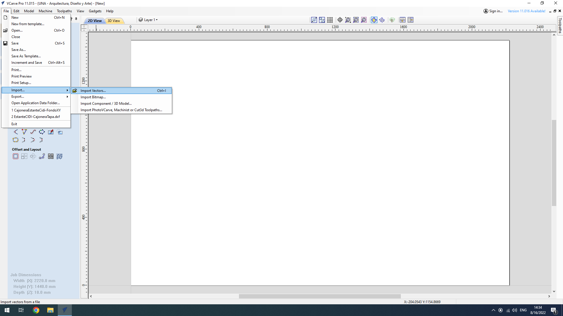
Importing the dxf file
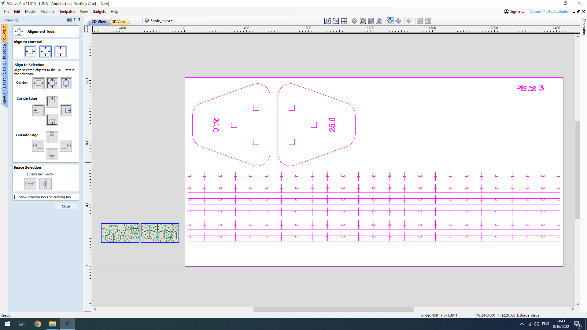
Aligning the vectors in the stock
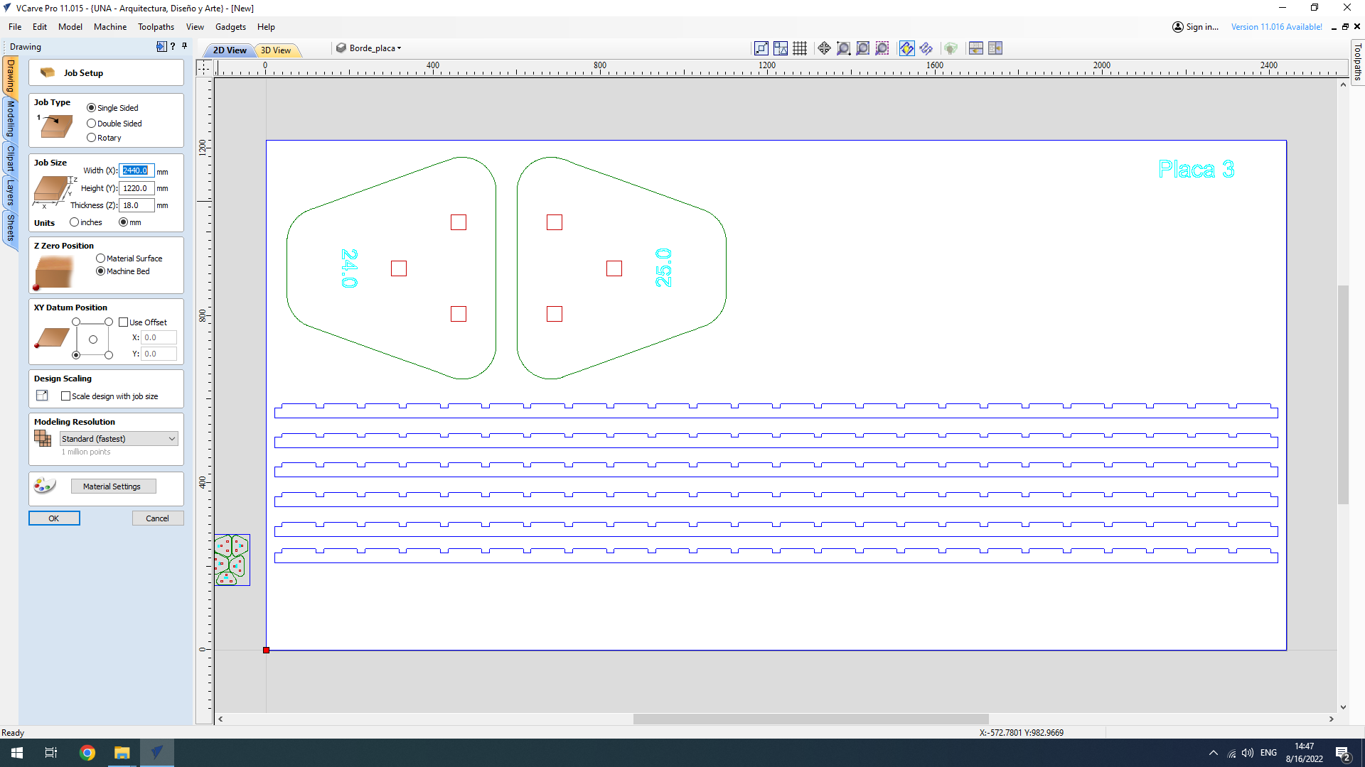
Veryfing stock dimmensions
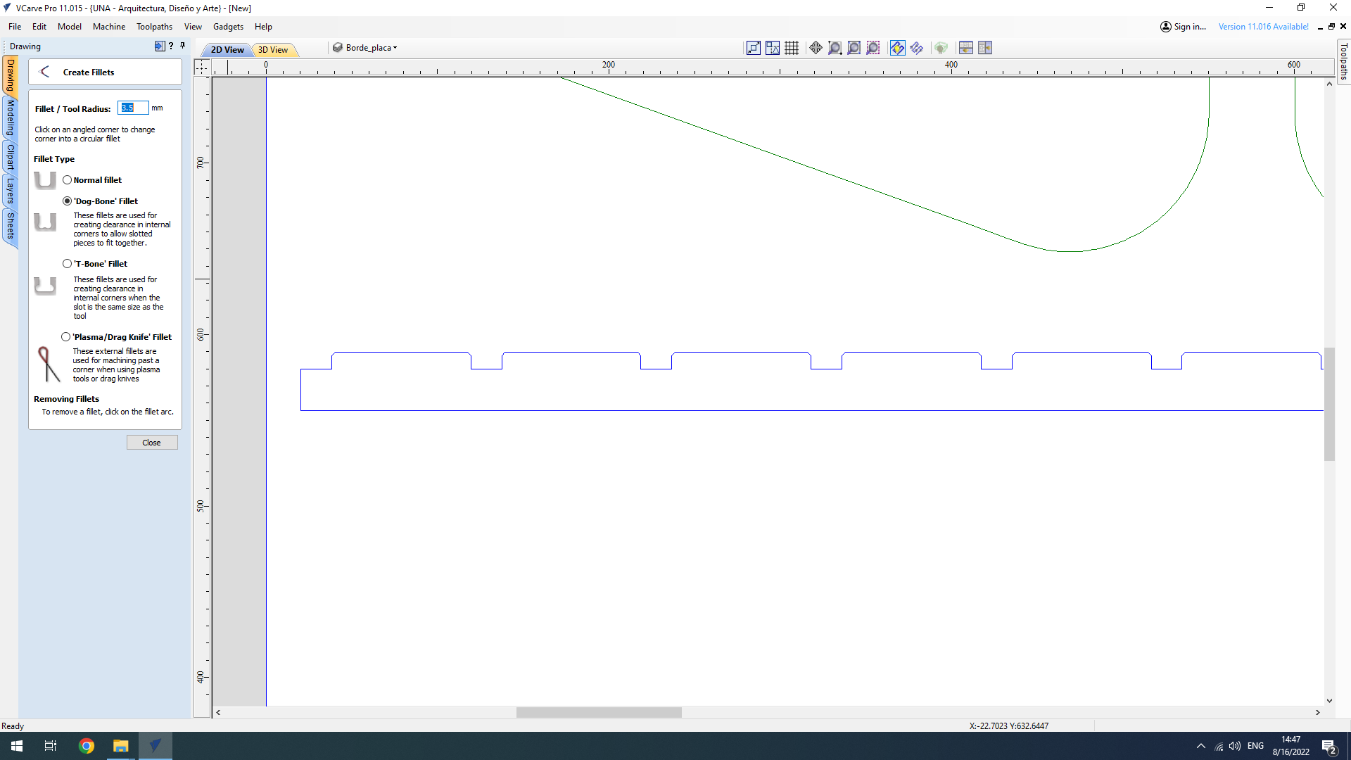
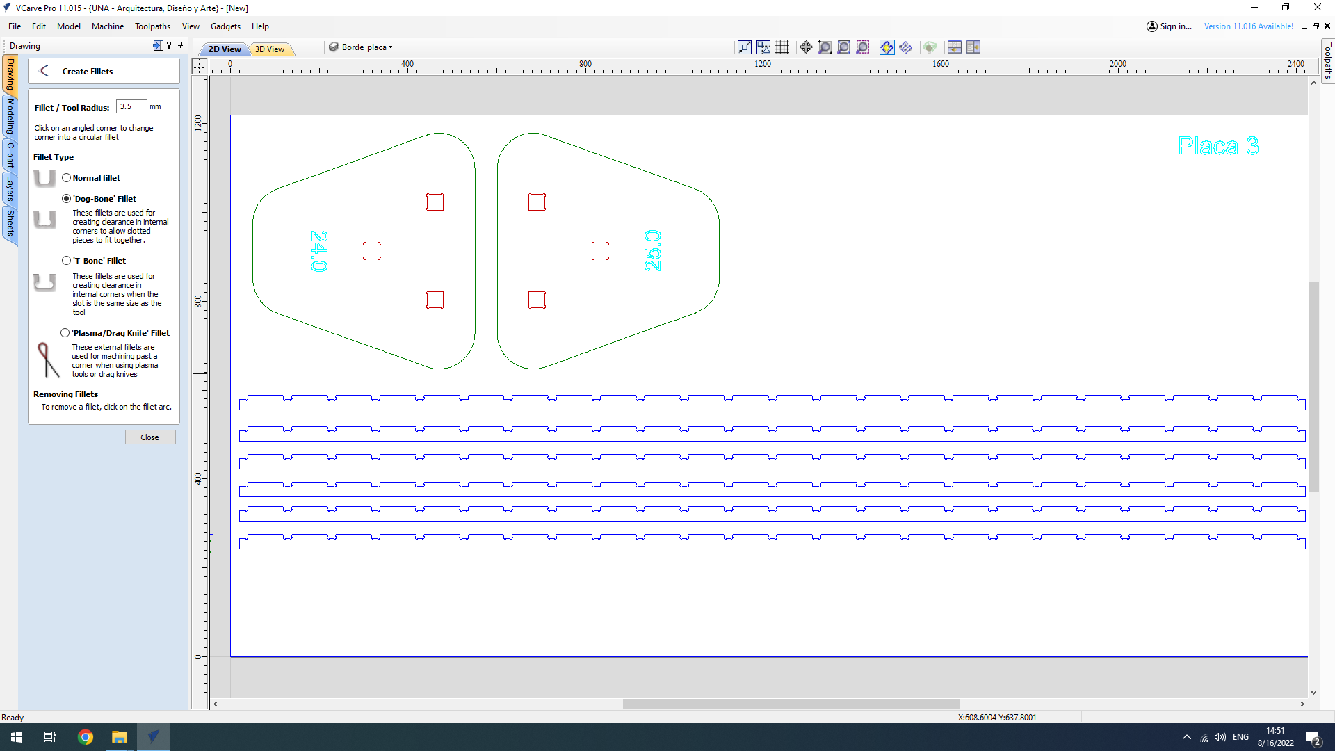
Adding Dog Bone fillets to lontigudinal pieces
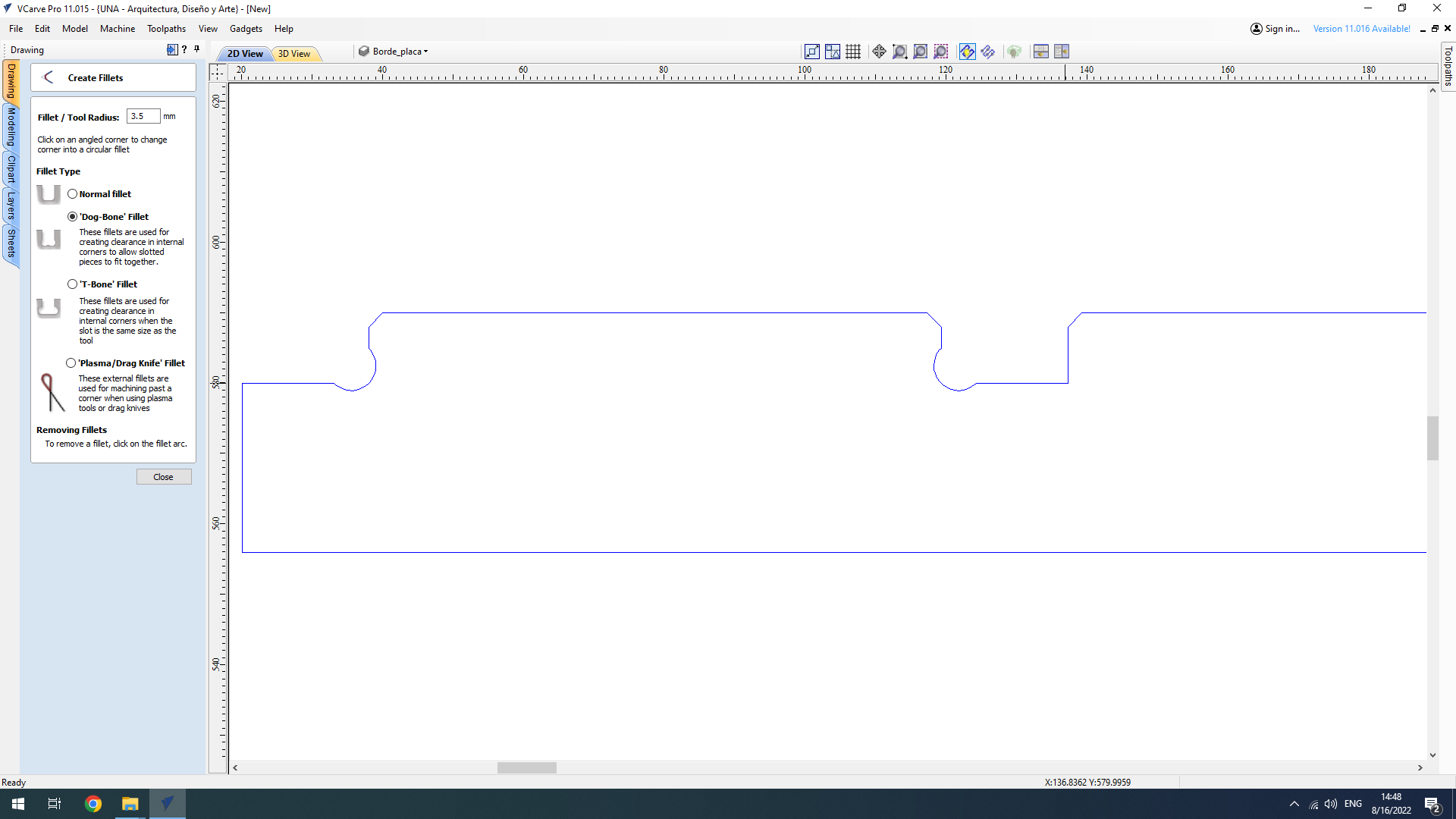
Adding Dog Bone fillets to lontigudinal pieces (zoom)
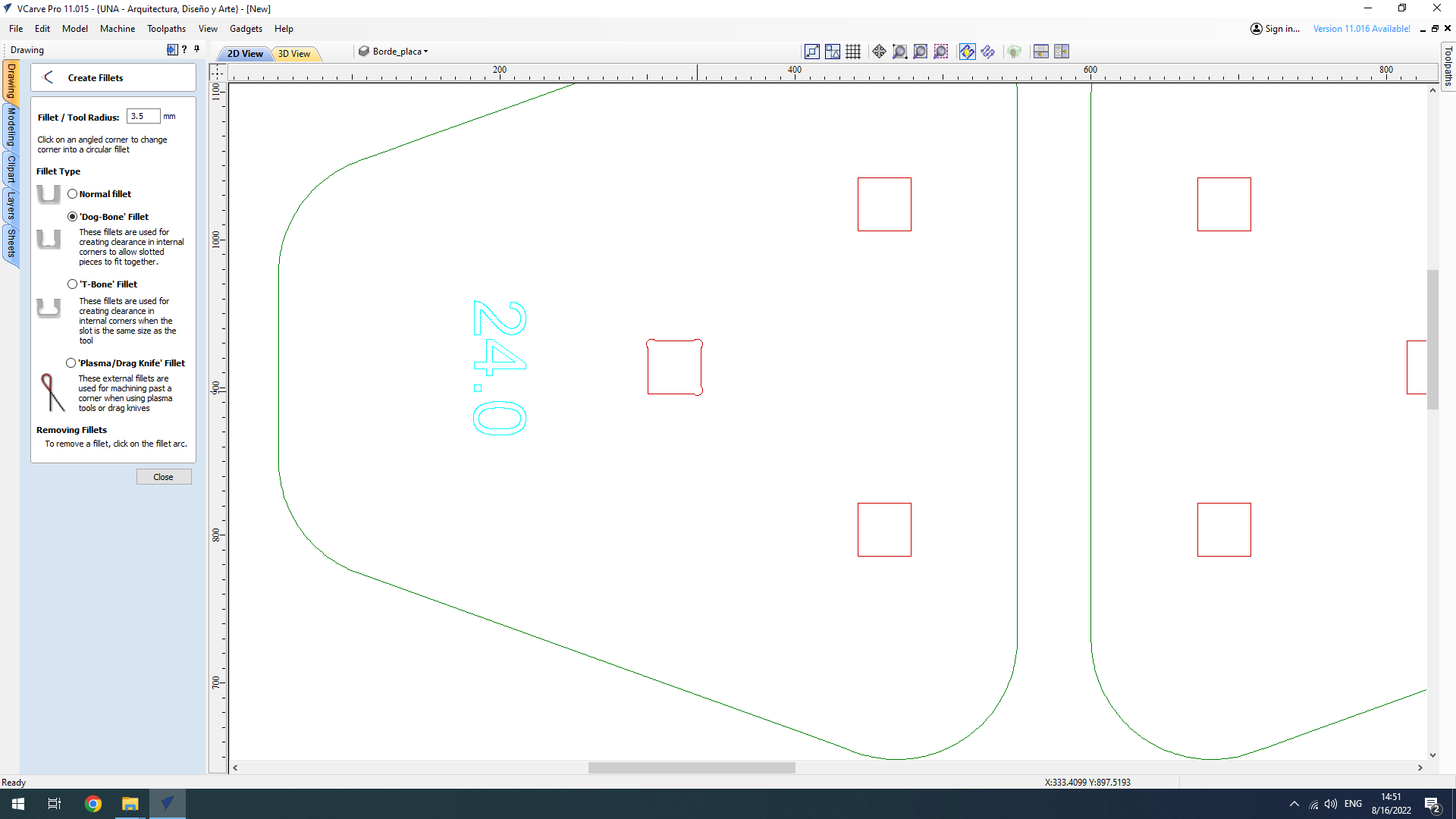
Adding Dog Bone fillets to transversal pieces
Stock ready for toolpaths
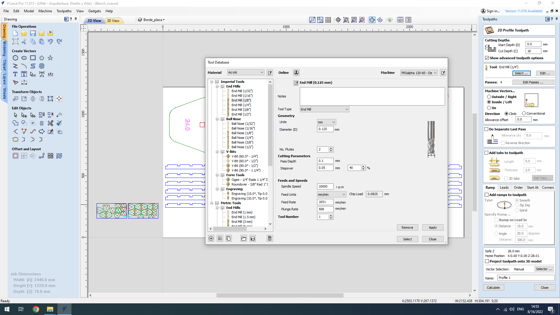
Toolpaths for texts - settings
Toolpaths for texts - settings done
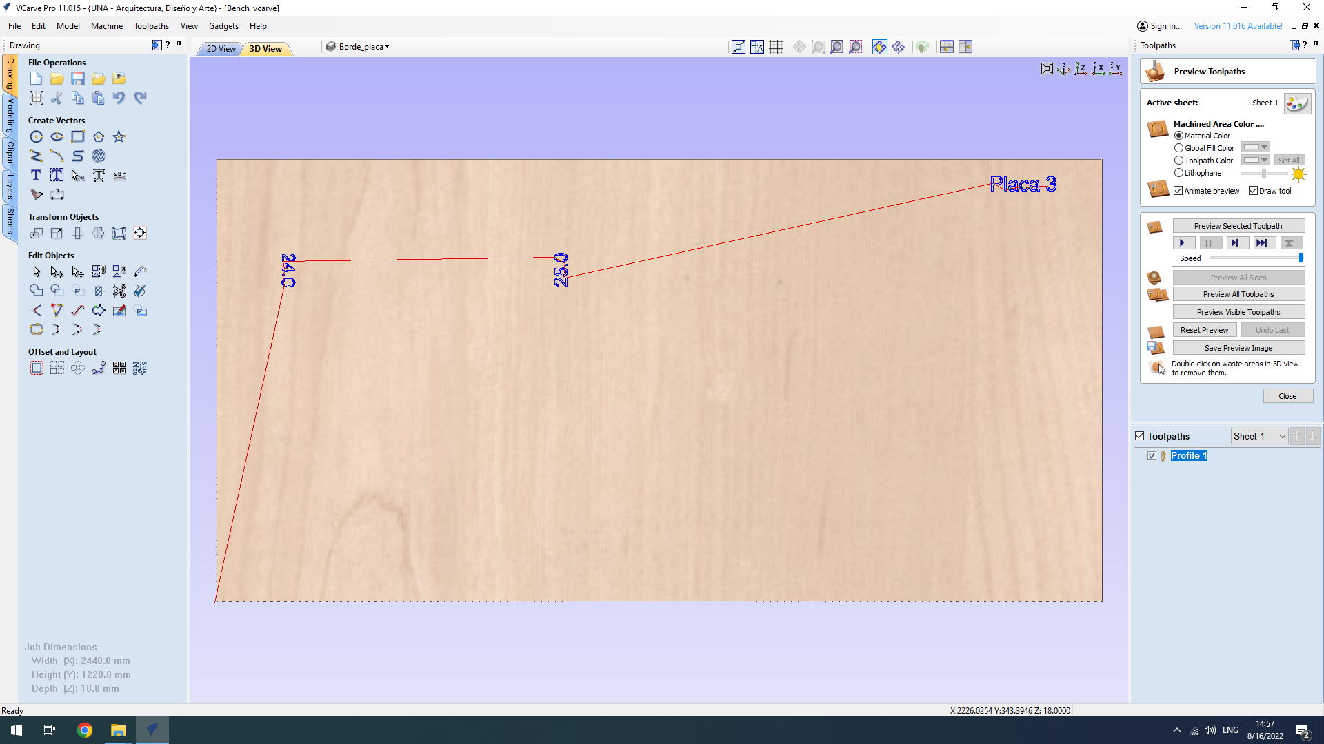
Toolpaths for texts - preview
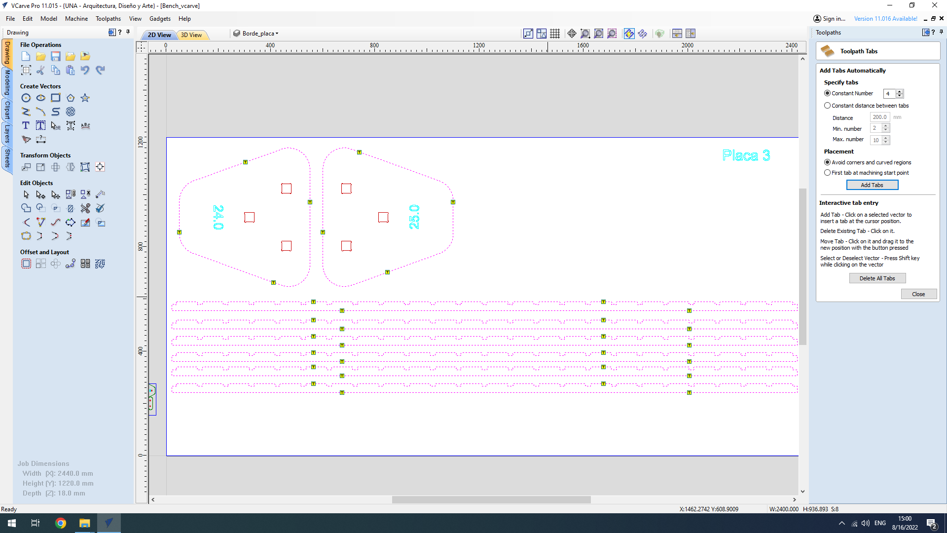
Toolpaths for cutout pieces - adding tabs
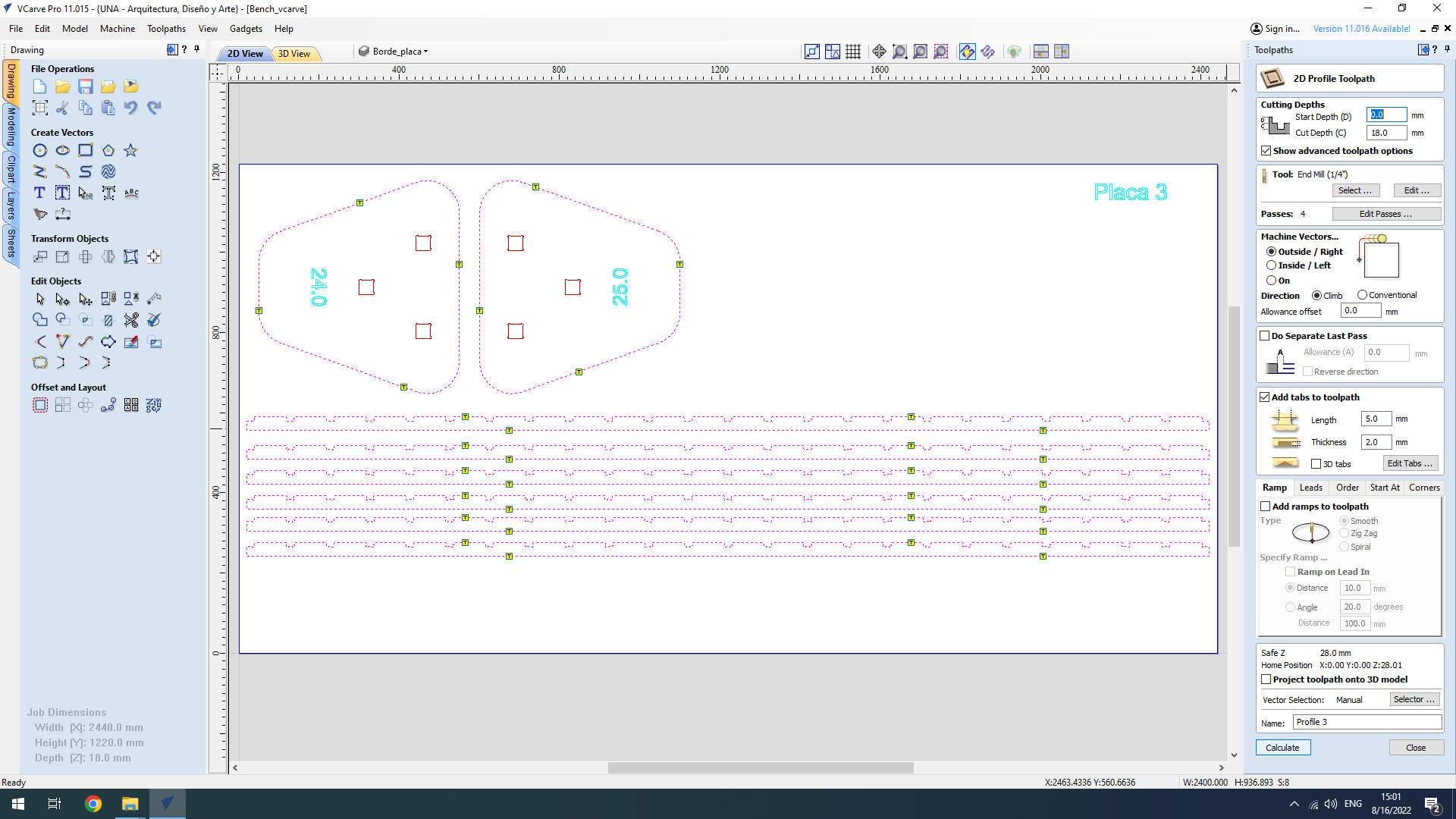
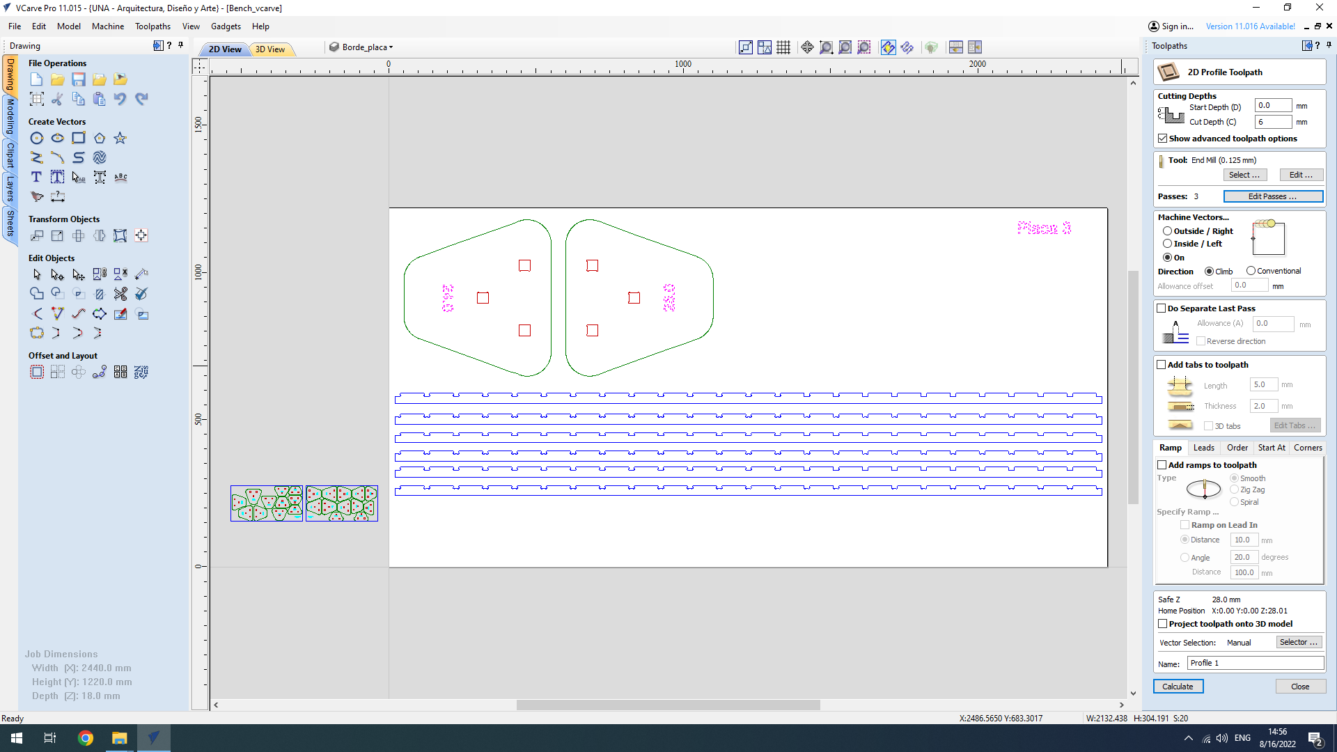
Toolpaths for cutout pieces - settings
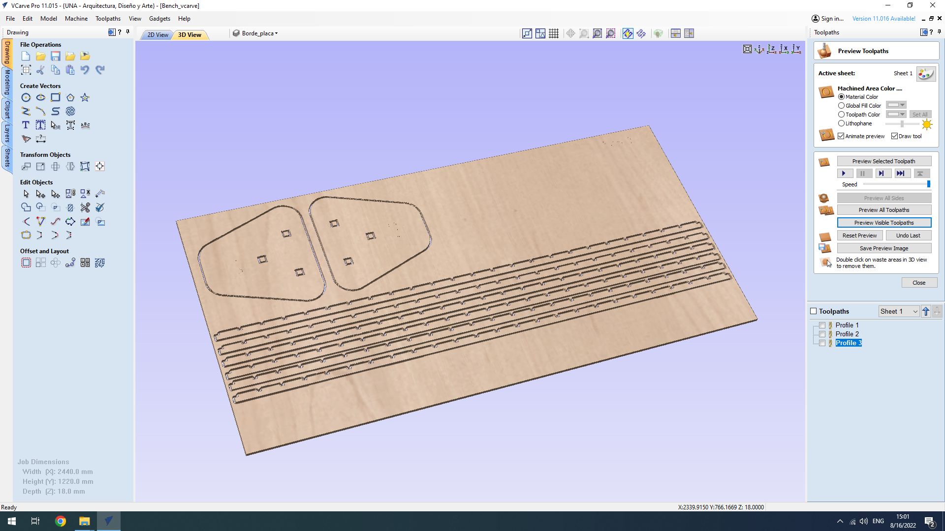
Toolpaths for cutout pieces - preview
The only part that was complicated to fabricate was the one that I initially thought it would be the easiest: the rectangular longitudinal beams. The subtractions for fitting the slices were small, and I had to figure out the carving process (“outside”, “inside” or “in-the-line”). Finally I used “inside” cuts that would preserve the size of the slots, with inner T bone corners. The longitudinal beams were 2 millimeters smaller than the holes, to compensate for the Kerf. Another problem was that the pieces were very long and thin (36 mm x 2400 mm) and I did not put enough “tabs’‘ on the fabrication process. Thus, two of the longitudinal beams were fabricated incorrectly.
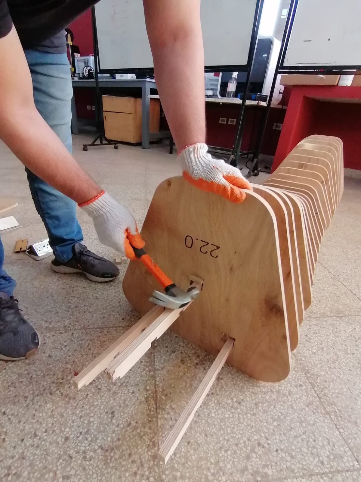
Assembly (on the harsh realities of the physical world!)
Even though I followed a great tutorial to develop the design, and I did learn a lot about Grasshopper, it omits the solution of very relevant problems in fabrication and assembly.
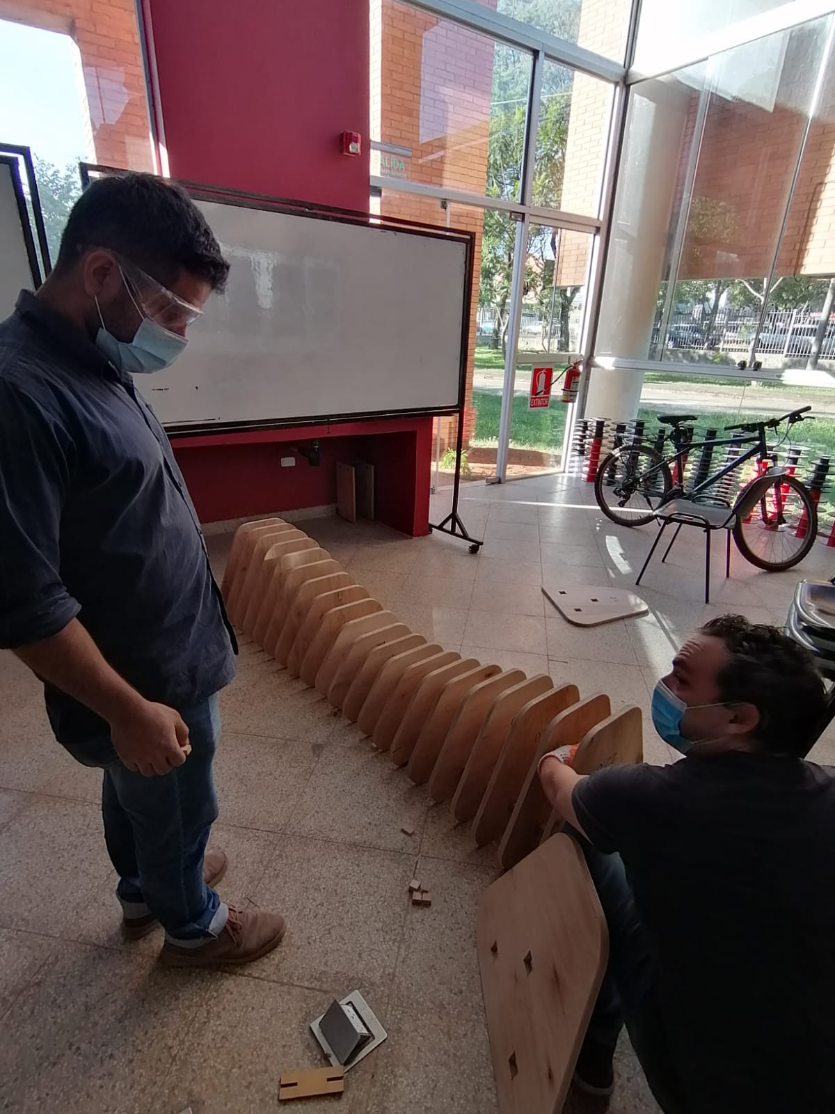
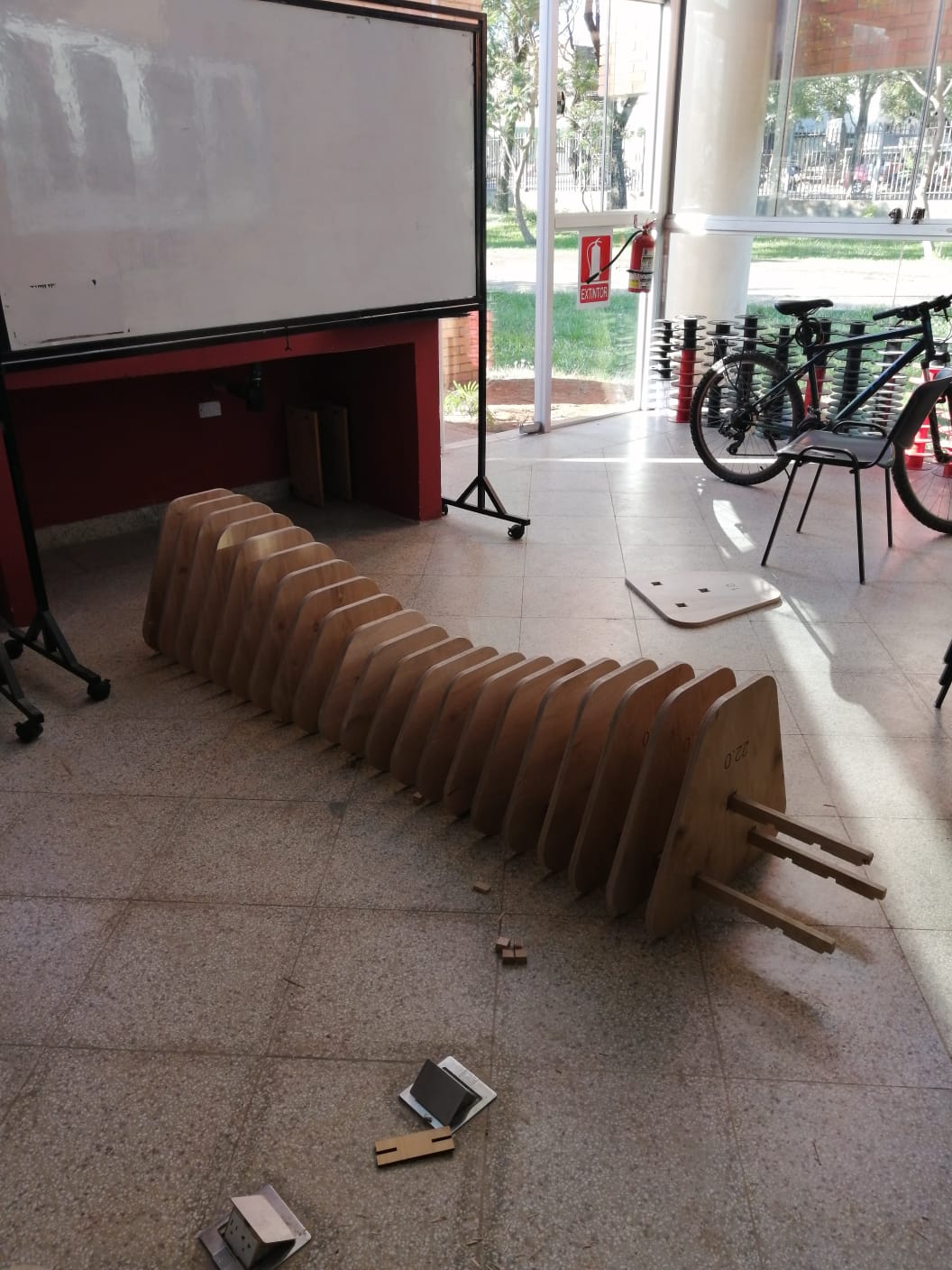
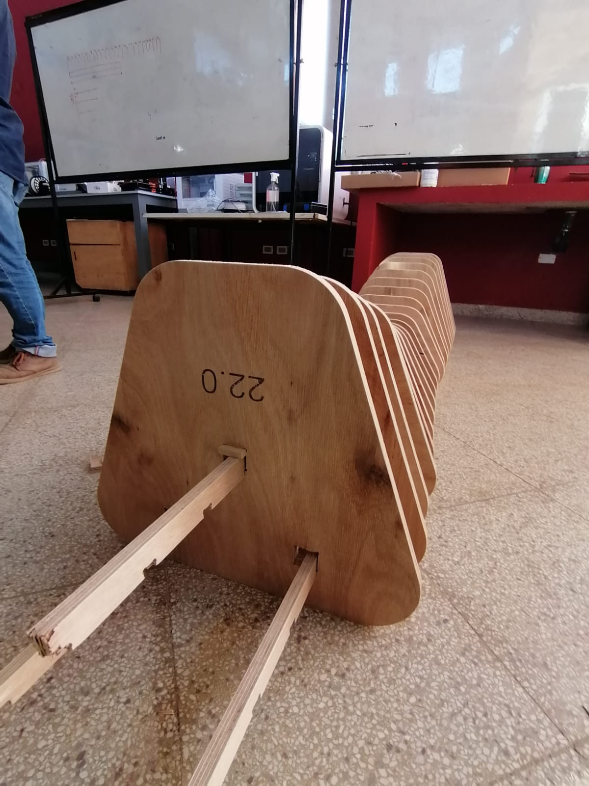
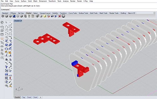
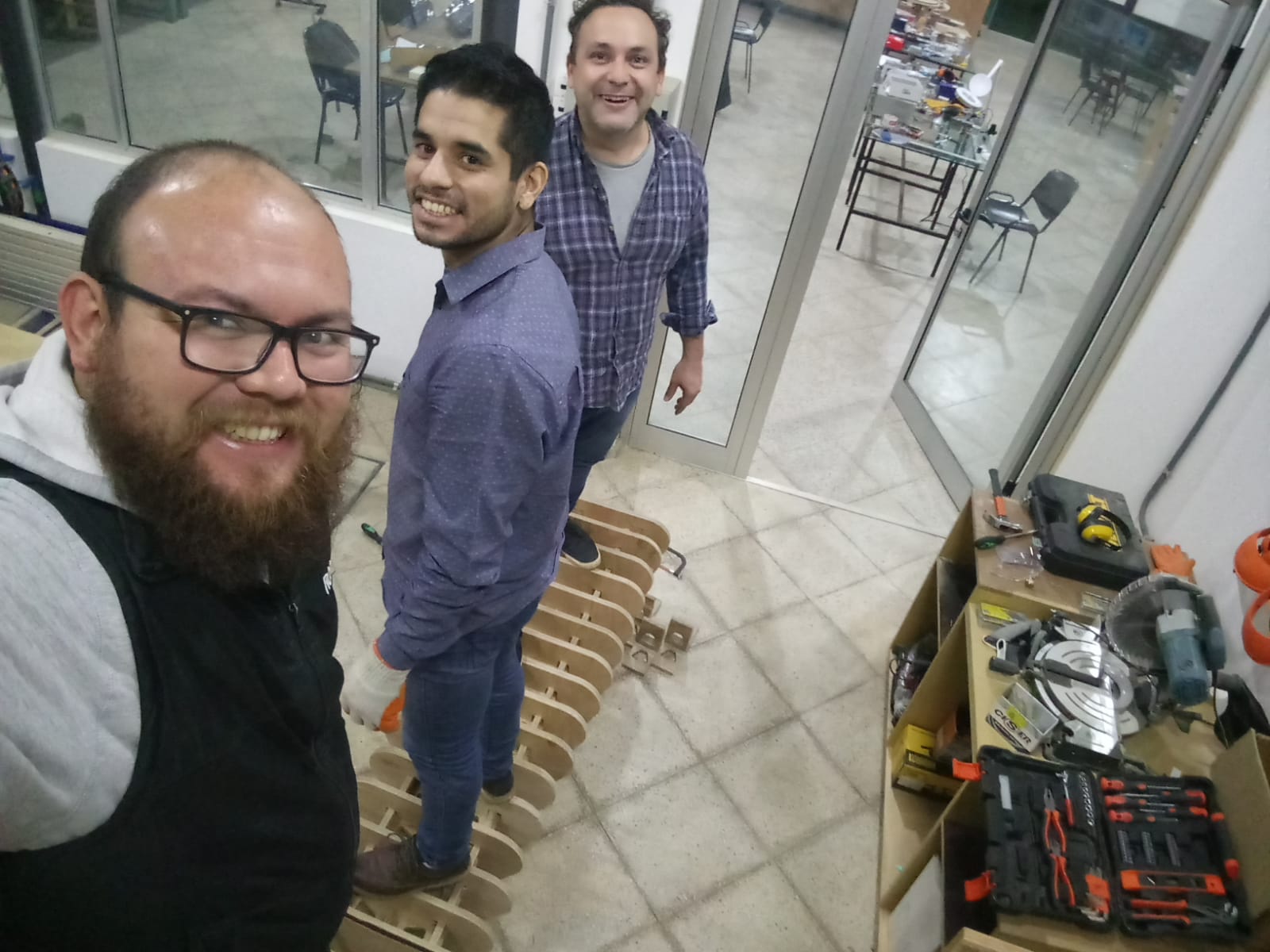
First, the tutorial uses the component “tubes” in grasshopper for the pieces that hold together all the slabs, the longitudinal beams that link the bench, if you like. The problem is that we do not have such cylindrical wooden pieces in the lab (or in local stores), thus I had to adapt that part of the programming using rectangular pieces. Furthermore, while being a great and rigorous exercise of grasshopper, the design did not make much sense as a physical construct. It linked all the pieces of the bench only with two longitudinal pieces. I added a third one, to improve stability Second, the realities of the assembly process are - of course - totally omitted in the tutorial and I had to figure that part out. It was very difficult to assemble all the parts. The bench has 25 slices. Slice 13 is the central piece, and for it to be placed at the center of the beam, it had to go through 12 tongue and groove slots and displace approximately 1,20 meters horizontally. Even worse, each slice had three holes and had to be properly placed in three longitudinal beams simultaneously. With a lot of work, and the help of my instructors Silvia and Abdon, and a hand given by Hans and Claudio, I could finally assemble the entire bench, at the end of Tuesday afternoon.
Lessons for the week:
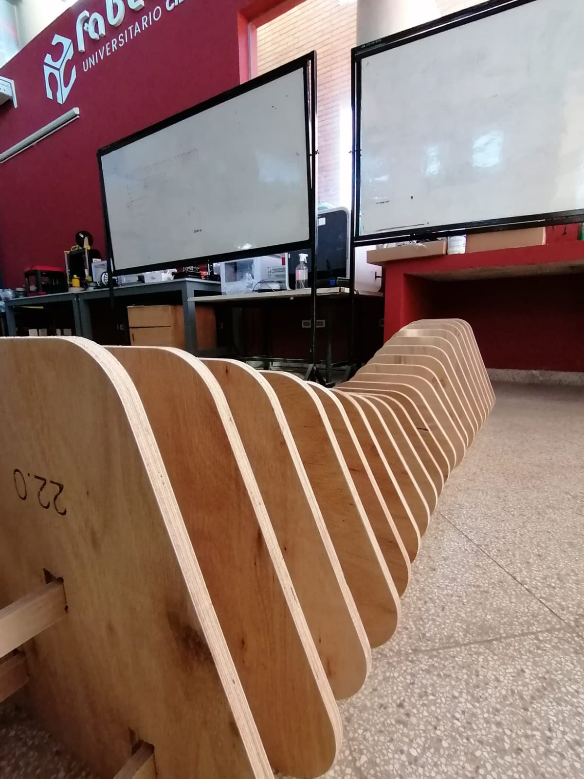
A proper digital fabrication file does not ensure a proper assembly in the physical world. The first iteration you actually build is the moment to help you find all the small contradictions, inefficiencies and unresolved aspects you did not consider while drawing the object on the computer. The logic of assembly is extremely relevant. I want to redesign the bench not with three long beams, but with a set of modular center beam-pieces that can be linked from the center and towards both sides. This would avoid the problems of sewing 25 slices through three different longitudinal axes, at the same time. In the real world things have weight! XD. Thus, once fully built, the bench bended slightly at the center. Thus, Now I am working to strengthen the bench by connecting all three longitudinal beams with additional parts. This way, the three separate pieces can become a single “T” beam and work together improving overall inertia. It is a workaround that allows the bench to function properly as a structure, without dismantling and reassembling everything.
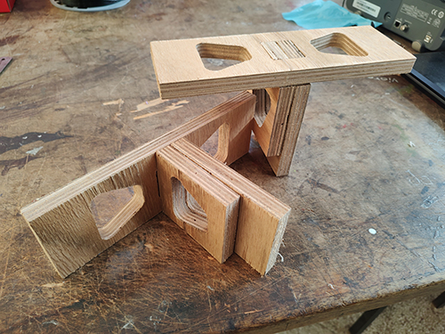
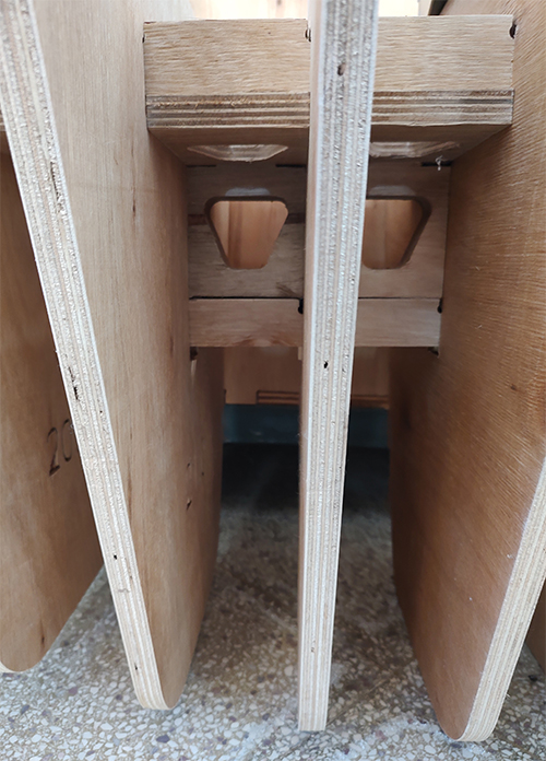
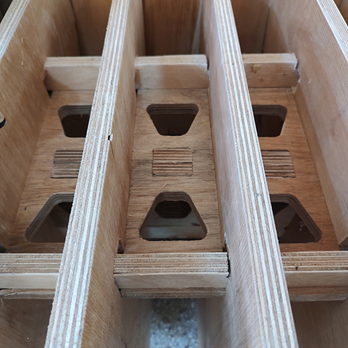
Update, May 29.
We succeeded, but in the end, Maxwell always wins.
Finally, we could finish the process of assembling a central “T” beam, linking the longitudinal beams. It was a delicate and time consuming process, and could have not finished without the support of Claudio Coronel. I tried to design an addition that does not look like an addition. I think the result is visually consistent. I like the fact that the “T” beam looks like the backbone of a large fish.
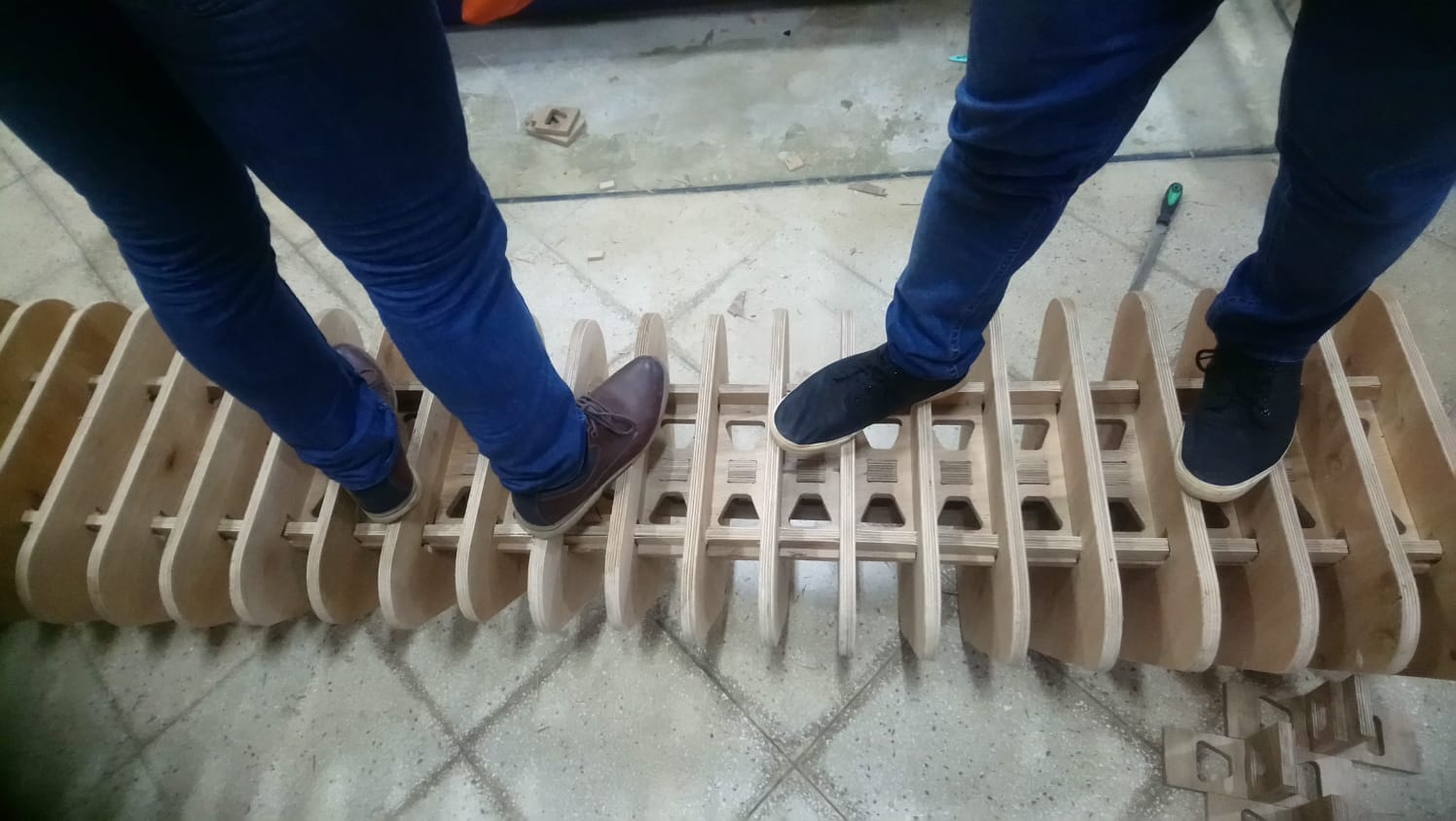
In structural terms, It has worked perfectly. The bench does not bend at the center anymore, and is strong enough to hold several adults standing on it, at the weakest structural point, the center. I have no doubt that if we had performed such tests prior to the reinforcement process, the bench would have collapsed. However, in the end Maxwell always wins. During class Neil presented us with the paper of Maxwell called “On reciprocal figures, frames and diagrams of forces”.
The paper explores the relationship between joints, restrictions and degrees of freedom. The conclusion is that we need to design at least one restriction for each possible degree of freedom, or the structure will be underconstrained. What we did, by assembling the “wooden backbone”, was to limit the rotation of each slice on the X axis, and the deformation (bending) of the entire bench on the Z axis. The problem is that now, the bench twists, because there are no restrictions in place to avoid torsion alongside the Y axis. In other words, not only does the central “T” beam look like a backbone, it functions as one, structurally. In a further cycle of development, (or in a further incarnation) I need to develop a way to add one more constraint to avoid this motion. In the meantime, the bench can be used as is.
Please see below some images of the design, fabrication and assembly process of this reinforcement.
Fabrication files here:
Link to the lab’s webpage:
Please see the tests for electronic design that we developed as a group here: