11. Output devices
Week 10 / March 30
This week’s assignment:
Group assignment:
- measure the power consumption of an output device
Measuring power consumption:
Individual assignment:
- add an output device to a microcontroller board you’ve designed, and program it to do something.
Controlling a Servo with PWM
Related to the final project, control of shades within Shadowhouse.
What I did
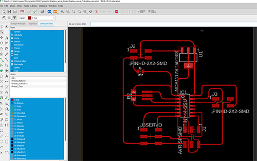
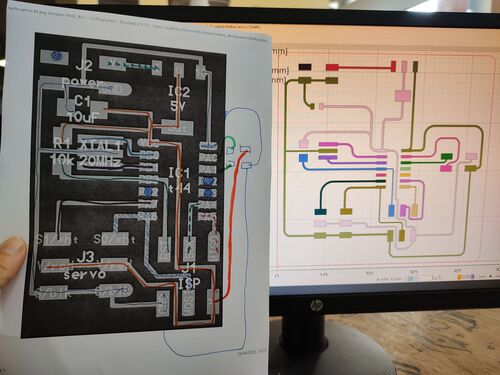
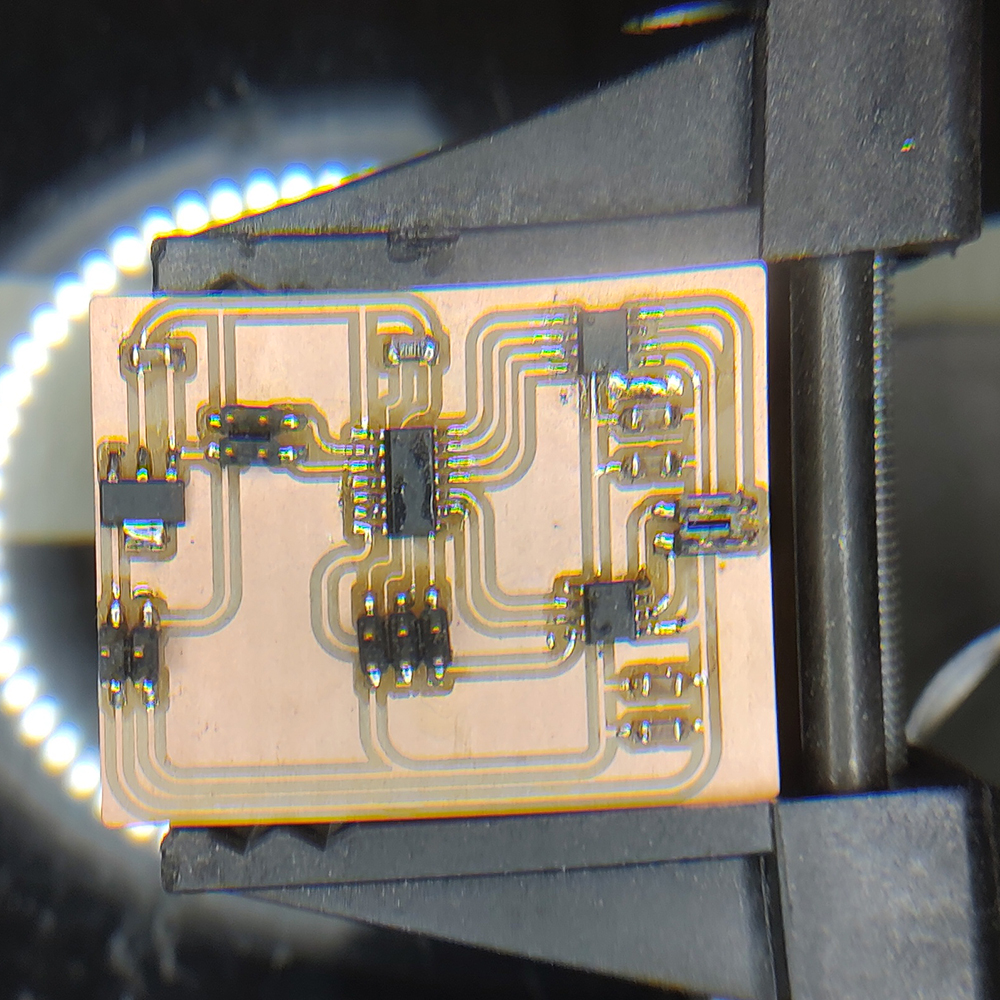
I designed a board, based on the Hello Servo Attiny44 example. I added one more RX TX pin to the board, in order to allow for easier connections with other PCBs, for the final project.
Problems in the fabrication process, soldering.
The board design requires several thin tracks under the 2x3 connector. With my lack of ability in soldering, I cutted off one of those tracks. Being Tuesday night remaking the board and programming it, in time, was not feasible.
Plan B
Idea 1 (Juanca) / Make a bypass
Result: servo board still not functional, Unable to go to the programming phase and assess how to control the servo using PWM.
Conclusion> Servo control board will not be ready in time
Idea 2 (Abdón) / repurpose a different board.
(Mr. Troche) can we program the hello echo board to control the board. ? Working with one of my instructors, Abdon, I explored the possibility of repurposing one of my previous boards - the hello echo button led - to control the servo. This was a temporary workaround to jump ahead with the programming phase even when the board made specifically for the Servo was permanently broken.
Development: use the Fading arduino template as base to control the servo, by using analogWrite(). This is an interesting approach to controlling the movement through PWM, since it does not control the movement to specific positions, but a gradual increase in the pulse width provided to the Servo. This is possible by setting the PWM output using analogWrite values from 0 to 255 and the delay.
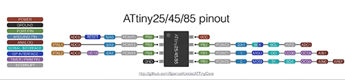
We looked for an arduino pinout and used Pin 5 as data & PWM output. (ATTiny 45)
Preliminary result: we can generate a square signal and move the servo. The issue is to find the values that correspond to the key positions of the servo (0, 90 and 180 degrees)
Conclusion
We can control and program PWM even in a board not specifically designed for that purpose. Our control with this software approach is still coarse, but effective, specially in terms of tunning or calibrating the servo, and the relation between position and pulse.
See example of code below:
int servo = 0;           // the PWM pin the servo is attached to
int pulse_width = 1;    // how bright the servo is

// the setup routine runs once when you press reset:
void setup() {
  // declare pin 5 to be an output:
  pinMode(servo, OUTPUT);
}

// the loop routine runs over and over again forever:
void loop() {
  // set the pulse_width of pin 5:
  analogWrite(servo, pulse_width);
  pulse_width = pulse_width + 1;
  if (pulse_width >40) {
  pulse_width = 1;
  }

  delay(300);
}
Updates: 09-05-2022
All done
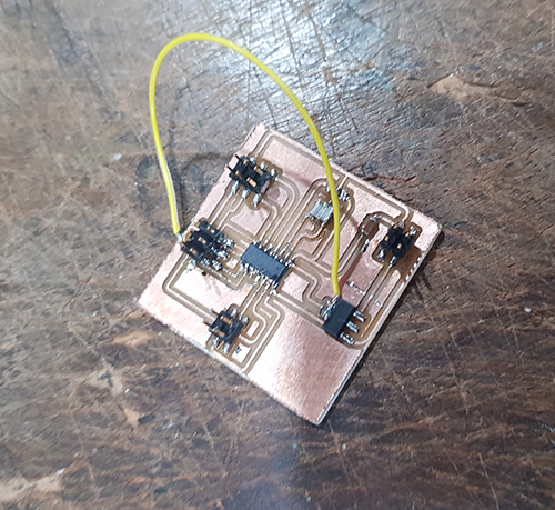
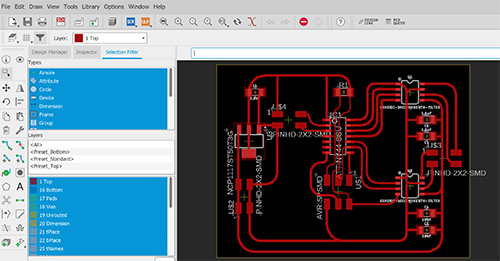
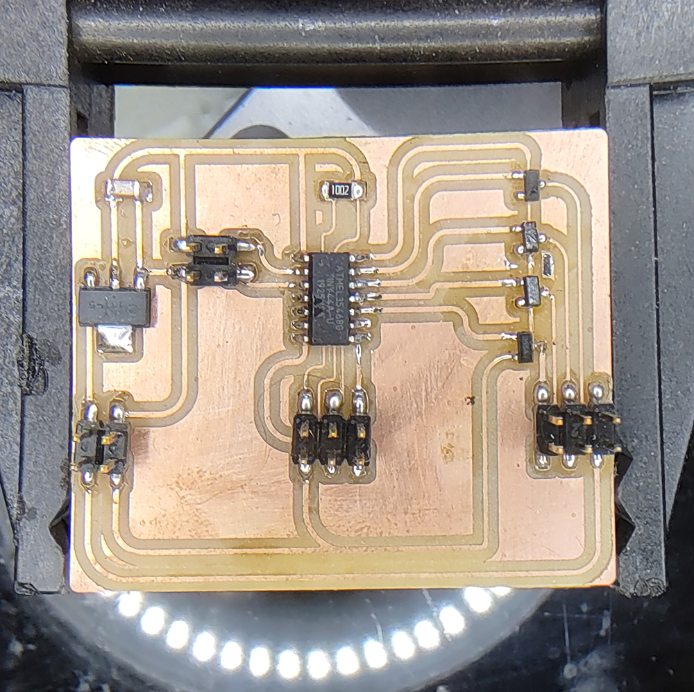
The board is fully developed and working well. To do this, I had to fabricate a new PCB and solder again. The fabrication of the PCB involved minor adjustments to ensure adequate milling on the Roland CNC, improving the performance of the tracks and avoiding unwanted continuities in the circuits.
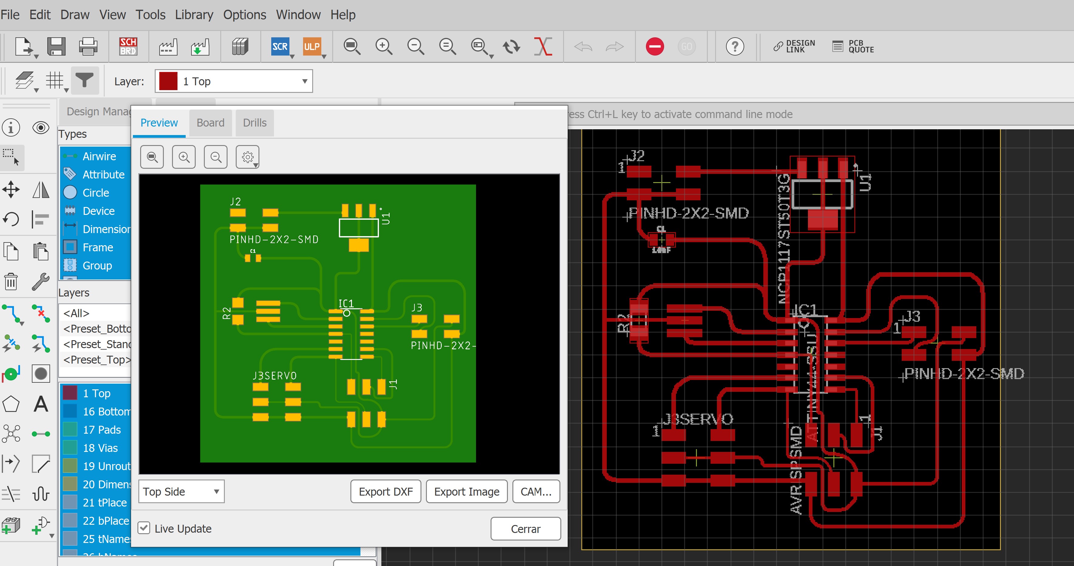
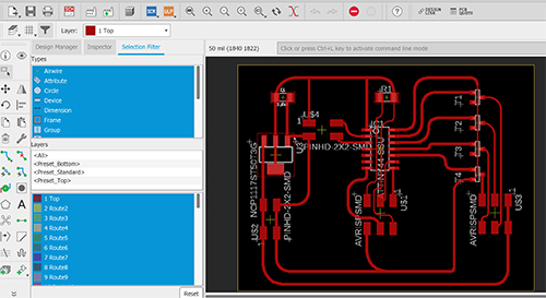
Adjusted Design
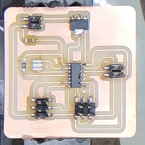
PCB Shadow servo, version 2
After that, I tried to program the C code examples of the fab academy Website. I received several errors, and then, after talking with my colleague Daniel I started debugging.
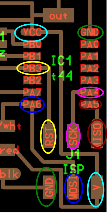
Debugging hardware
Using the multimeter to test for continuity and could isolate a problem in the connection from SCK to PA4. I reinforced the soldering and tested continuity again confirming that the board was functioning properly.
After the hardware debugging phase concluded, I could reach the programming phase. For this I used the C code example for one servo. Unfortunately, after successfully programming the servo did not work.
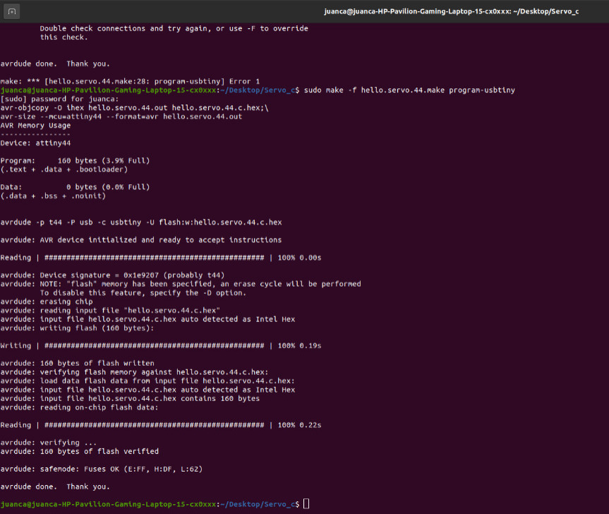
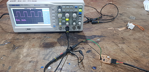
Thus we had again to tune the servos, using the oscilloscope.
After some work, we could calibrate the pulse for both programs, and successfully operate one servo and two servos.
What I have learned in this process (longer than a week).
-
It is possible to (vaguely) control a servo using a board not specifically designed for this. Also, and this is entirely the merit of Abdon, to control the position not through an “initial position / final position” approach, but through an “standard increase in standard delay period” approach, based on a program originally designed to control a dimmer light.
-
The “dimmer” approach is not precise, but is useful as a basic tool to tune the servo, in other words, to determine the input counts in the software that lead to the classic angular positions of a servo, namely 0o, 90o and 180o
-
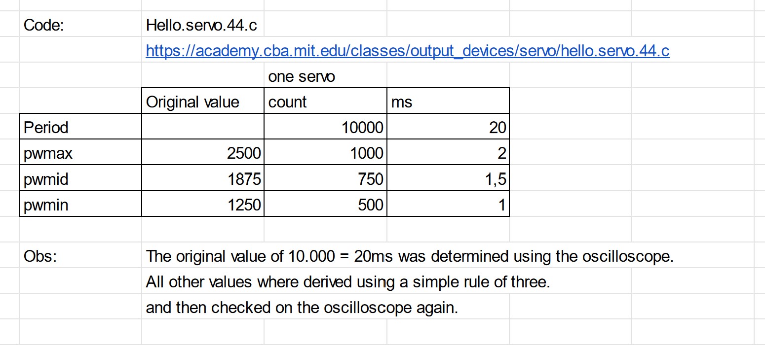
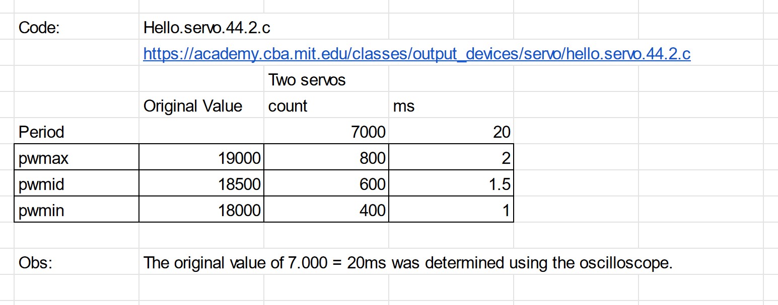
Somewhat surprisingly, I found out that the count values that correspond with pulse-width signals in the template code provided need to be adjusted. I am not sure why this is the case. I know I can adjust any count value to its corresponding pulse-width using the oscilloscope, and that through this calibration, I could reproduce the movements and know the values that correspond to classic angular positions for the two kinds of servos that we have here on Lab.
-
Even more surprisingly, I found out that even values which are calibrated with the oscilloscope, produce slightly unequal movements on different servos. For instance: The HKSCM16-6 servo works in the count range between 6 and 36, and moves something around 170 degrees. The HK15178 works in the count range of 7 and 37, and moves 179 degrees.
I will keep exploring these details on the development of my final project.
Bonus Track: 22-05-22
I have developed two more output boards, a Hello Stepper bipolar and a Hello Stepper Unipolar. I am working on the Stepper PCBs because I want to be able to explore further options to move the blinds of my final project, even if it is after finishing the Fab Academy, in further cycles of development. I believe that variations using Steppers may be very useful to optimize the motion of the blinds. For instance, to move two different vertical levels of blinds with just one Stepper motor, instead of two or four smaller servos.
As with the shadow_servo PCB I added one more RX TX pin to the stepper boards, in order to allow for easier connections with other PCBs.
Shadow_Stepper_Bipolar.
Shadow_Stepper_Unipolar.
Design and fabrication files here:
Shadow Servo:
Shadow Stepper Bipolar:
CNC Shadow Stepper Bipolar (inside)
CNC Shadow Stepper Bipolar (cutout)
Shadow Stepper Unipolar:
CNC Shadow Stepper Unipolar (inside)
CNC Shadow Stepper Unipolar (cutout)
Link to the lab’s webpage:
Please see the tests for electronic design that we developed as a group here: