17. Applications and implications
Week 17 - May 18
What will it do?
Shadowhouse is an attempt to reframe organic vegetable farming on a reduced scale. As the most soybean intensive country in the world (measured in exported tons / country surface) Paraguay has faced a radical transformation of the landscape, and modes of living of peasant communities in the last four decades. Such massive process of change, lead to many negative externalities, which include deforestation, the displacement of the aforementioned peasant and native communities and a significant reduction of vegetables and fruits production, since these crops are deemed not competitive against classic oilseeds which are the backbone of agroindustry. This has led to the paradoxical situation in which Paraguay, a global breadbasket country, is presently importing fruits and vegetables for local consumption.
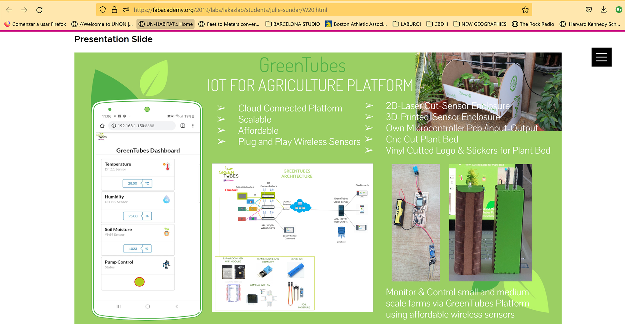
Shadowhouse proposes a responsive armature for dense vertical farming. A Shadowhouse is by definition the opposite of a greenhouse, considering that in general terms, the largest challenge for the cultivation of vegetables in Paraguay is not to face a harsh winter, but excessive heat and light. The idea of developing a modular and responsive armature is an attempt to build capacities to make such crops more predictable, and more profitable, while producing more food in less surface area. At this stage in Fab Academy, I will develop one light sensor as input and two PCBs to control stepper motors and servo motors. The combination of the input sensor and the output PCBs will result in a series of cultivation modules equipped with blinds that will be automatically operated. The functioning of the blinds is programmed to be inverse in relation to light levels. In other words, with more light, the blinds shut. With less light, the blinds open.
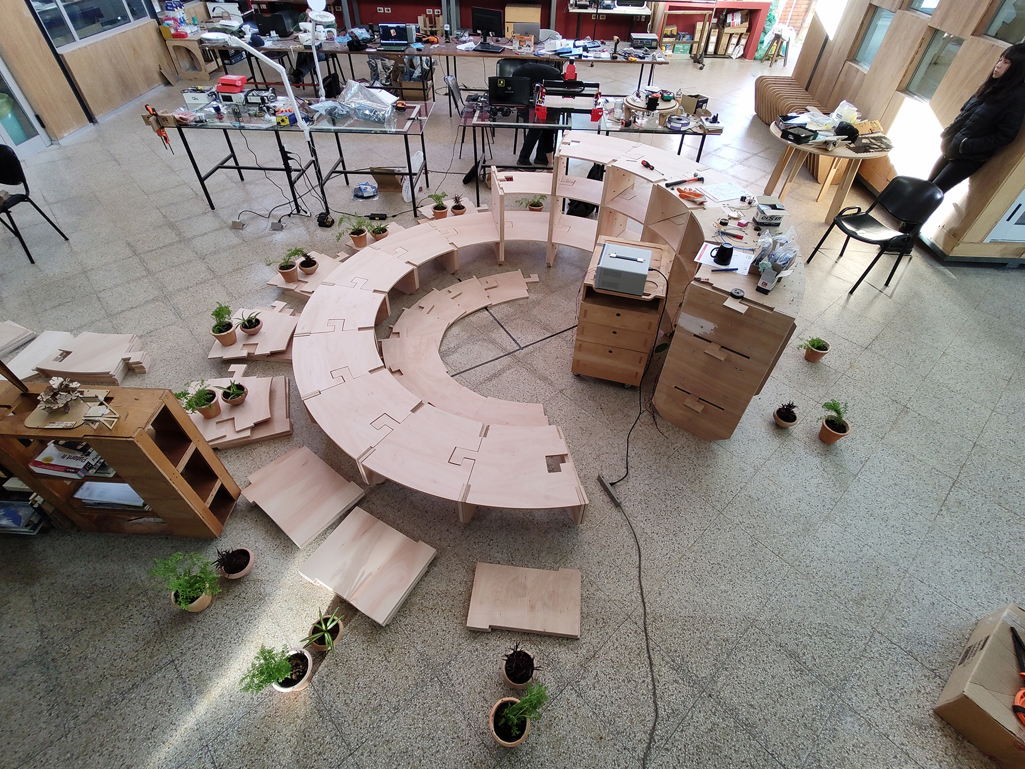
Image: Assembly process of the first level
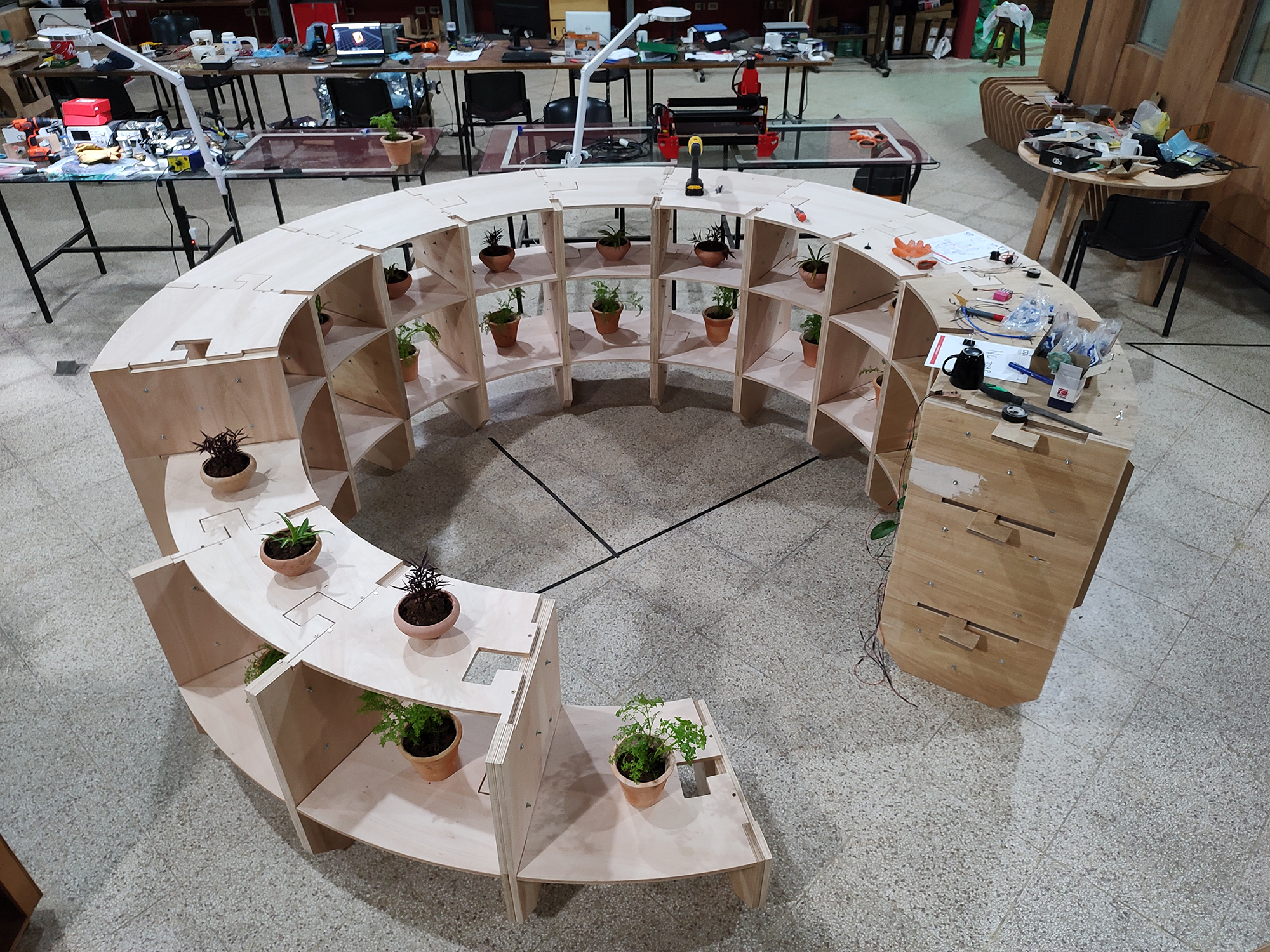
Image: first level assembled
Video: blinds working
Who’s done what beforehand?
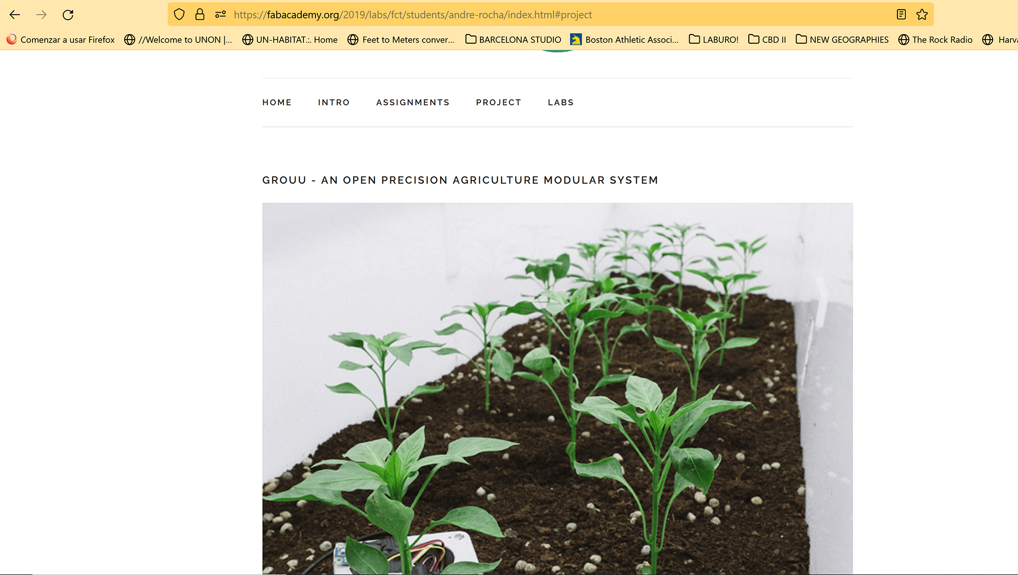
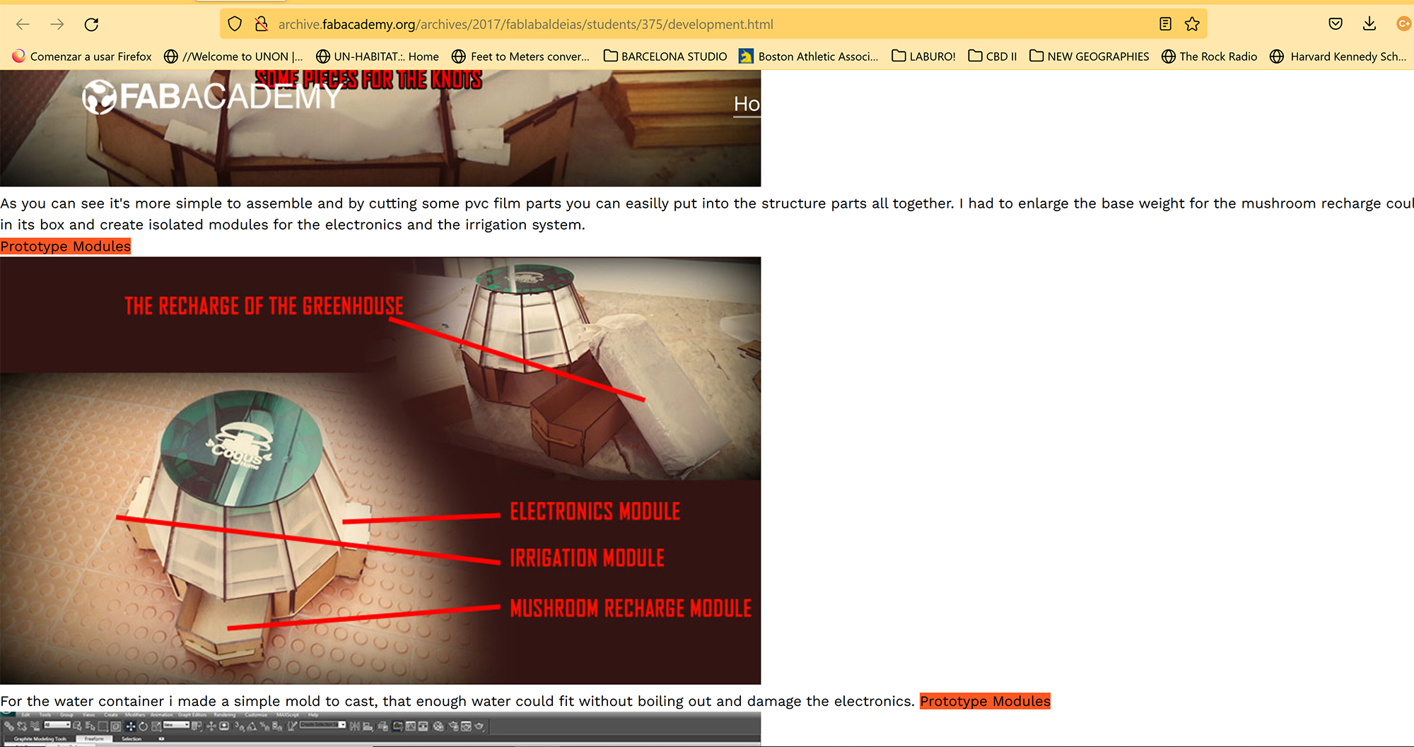
I have looked for precedents in the works of fellow fabbers.
What will you design?
Object Design:
The framework is a cylindrical wooden structure, contained in a 3x3x3 meters cube. (approximately 9,5 x 9,5 x 9,5 feet). The concept is that the structure closes and opens according to the amount of light received. The critical orientations for the southern hemisphere are North, East and West, as the ones with higher exposure to sun radiation and heat. South orientation (from south east to south west) does not require shades. Thus, the South facade contains the access to the interior workspace. Draft drawings of Object Design were made in graph paper and boards. Basic CAD Drawings were developed in Rhinoceros Software. Final drawing was developed in Autodesk Fusion 360 software.
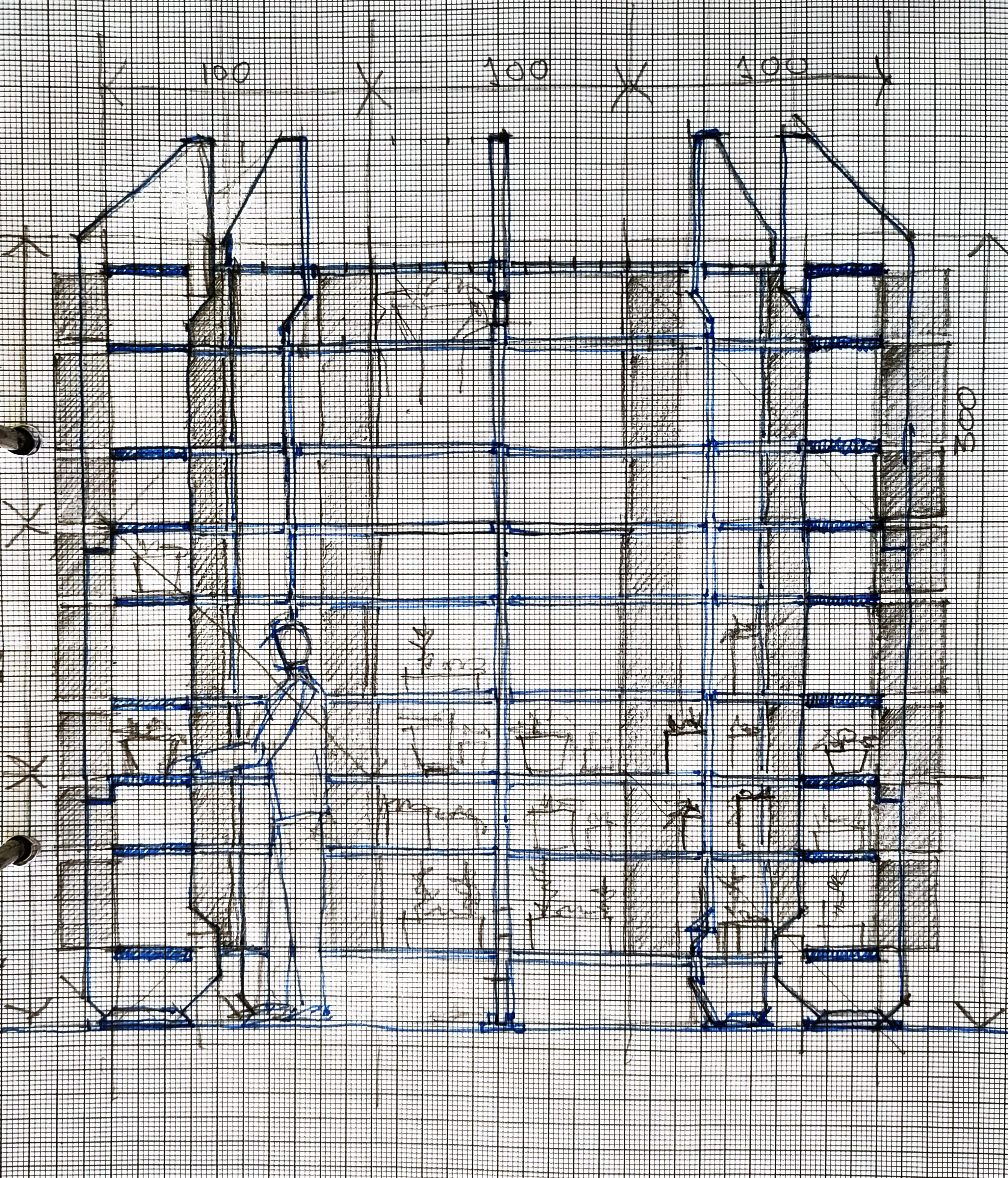
Image: Initial Sketch - North Section
Mechanical Design:
The mechanical design involved several parts:
- Holders for the servos,
- Holders for the bearings,
- Transition and connection between motor or bearing and the blinds.
- The blinds,
- The transmission rods,
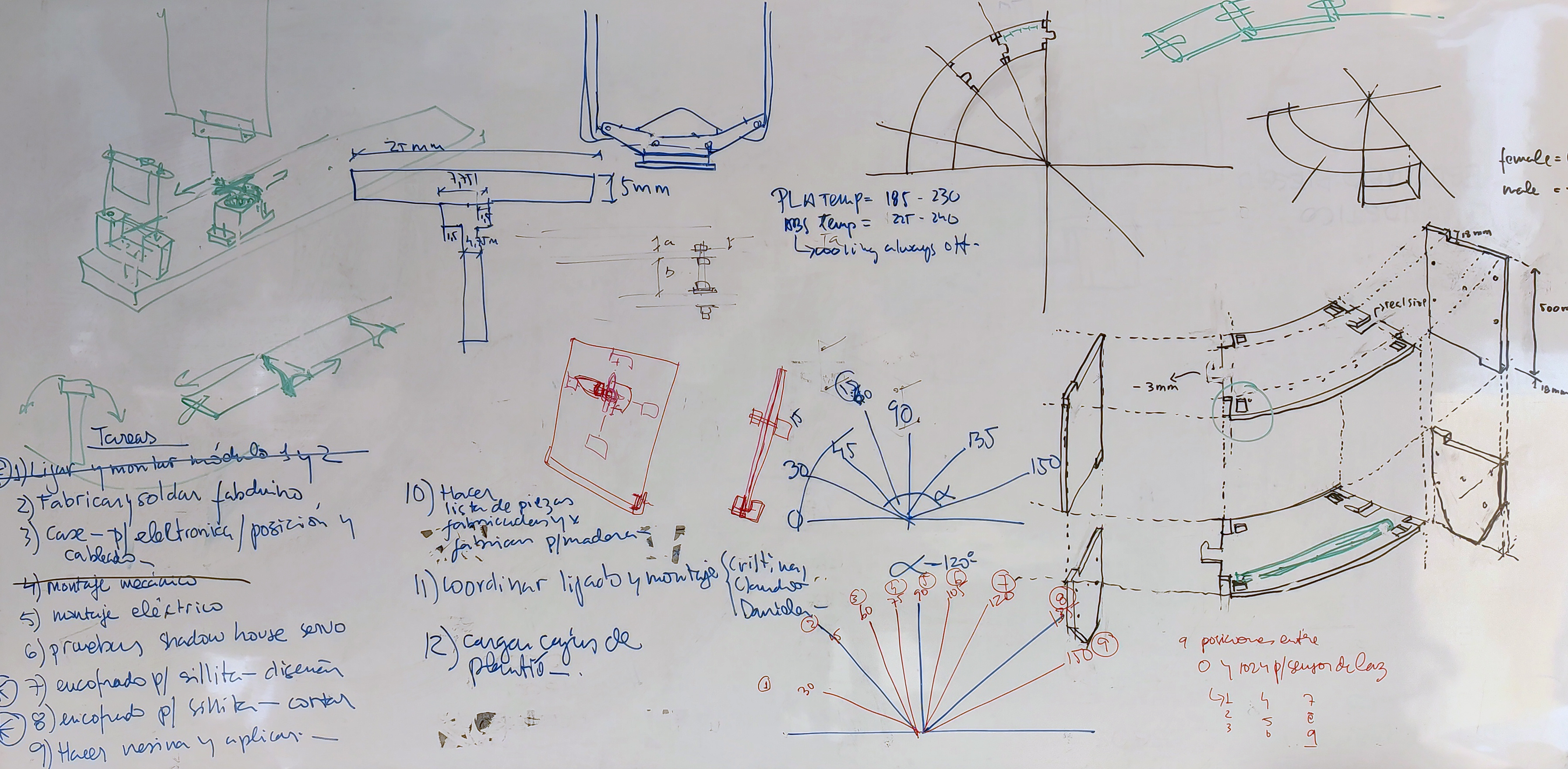
Image: Conceptual drawings - Mechanical Design, Object Design.
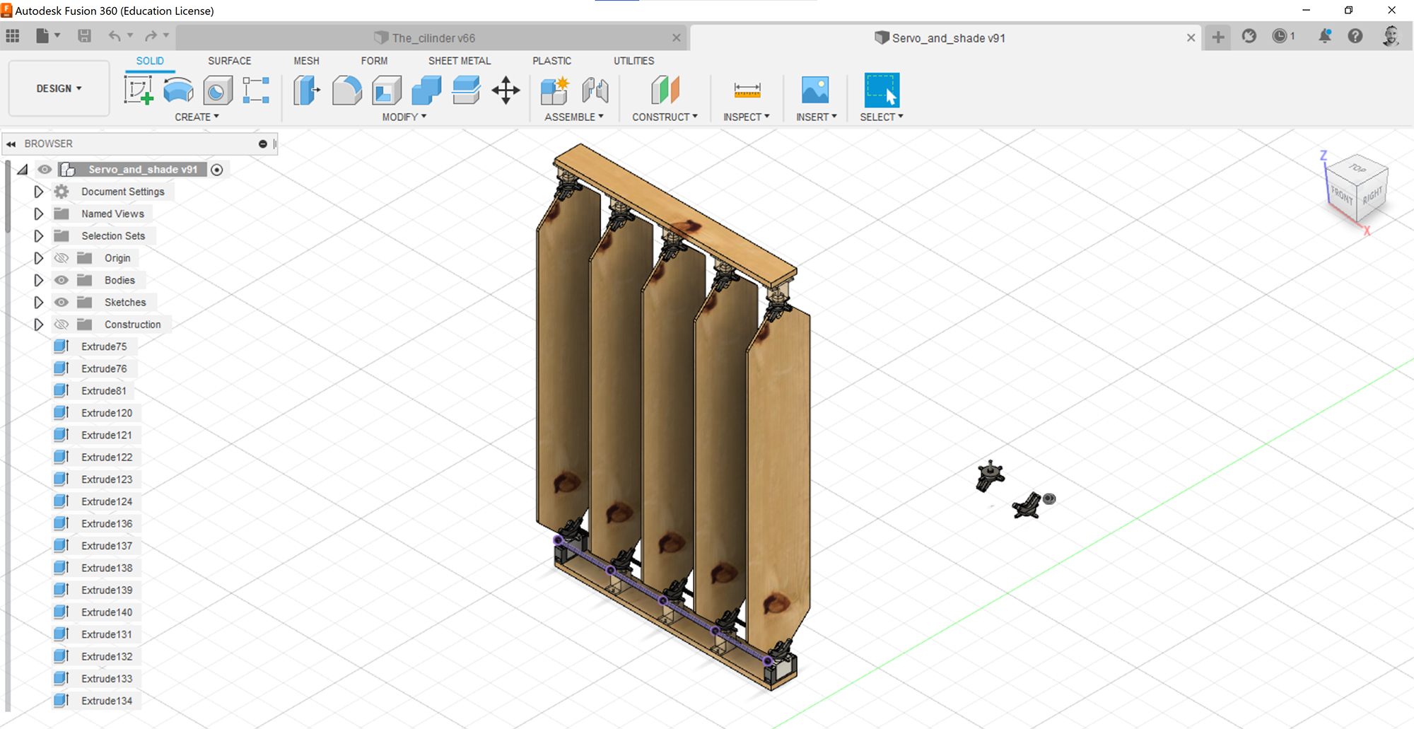
Image: Detail drawings in Fusion - Mechanical Design.
3d Preview in Fusion: Mechanical Design.
Electronics Design:
Input sensors: I have developed a PCB with a phototransistor which constitutes the light input for the device.
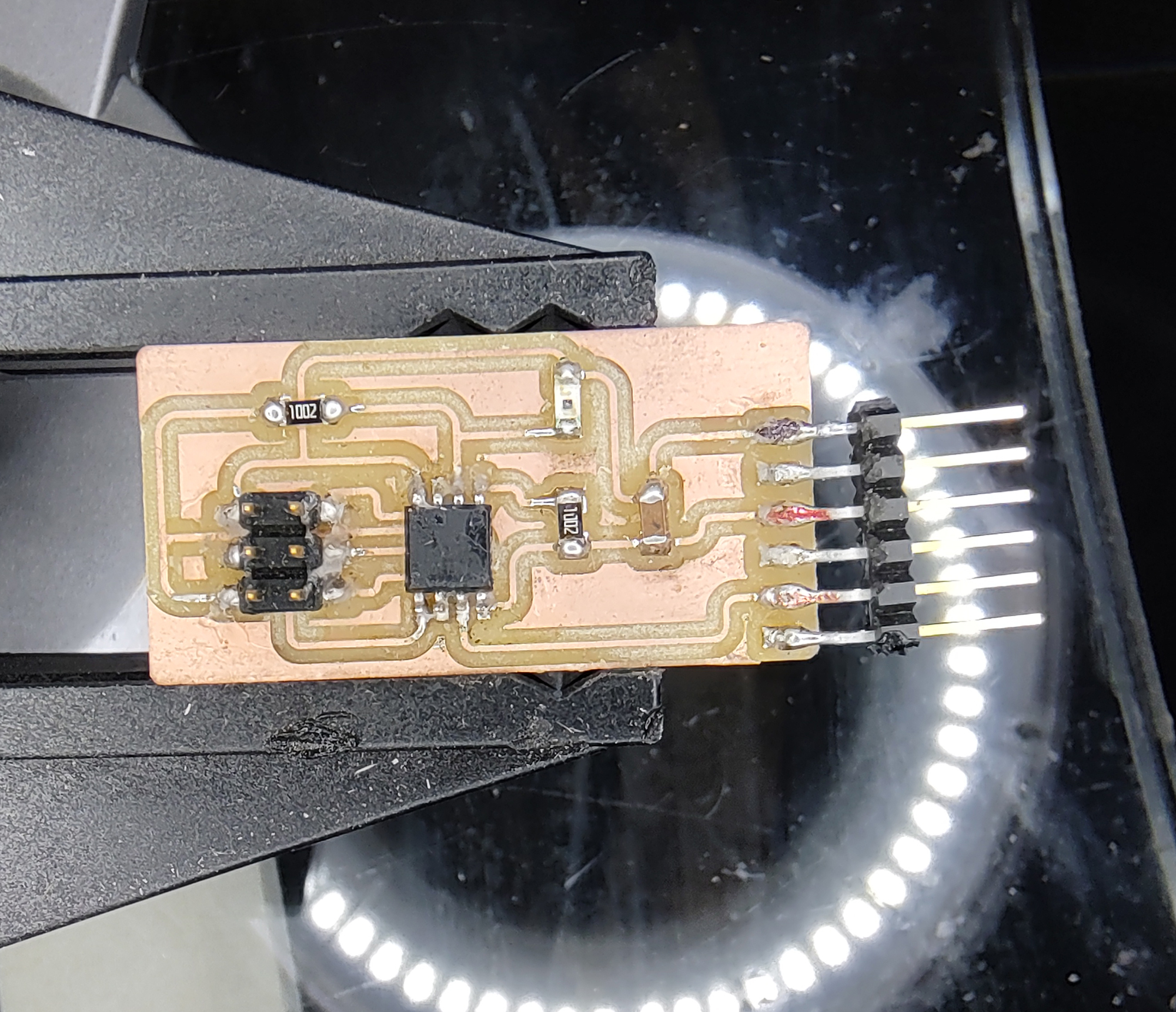
Image: Light Sensor PCB.
Output devices: I have developed three different output modules:
- The first one is a PCB that controls servos.
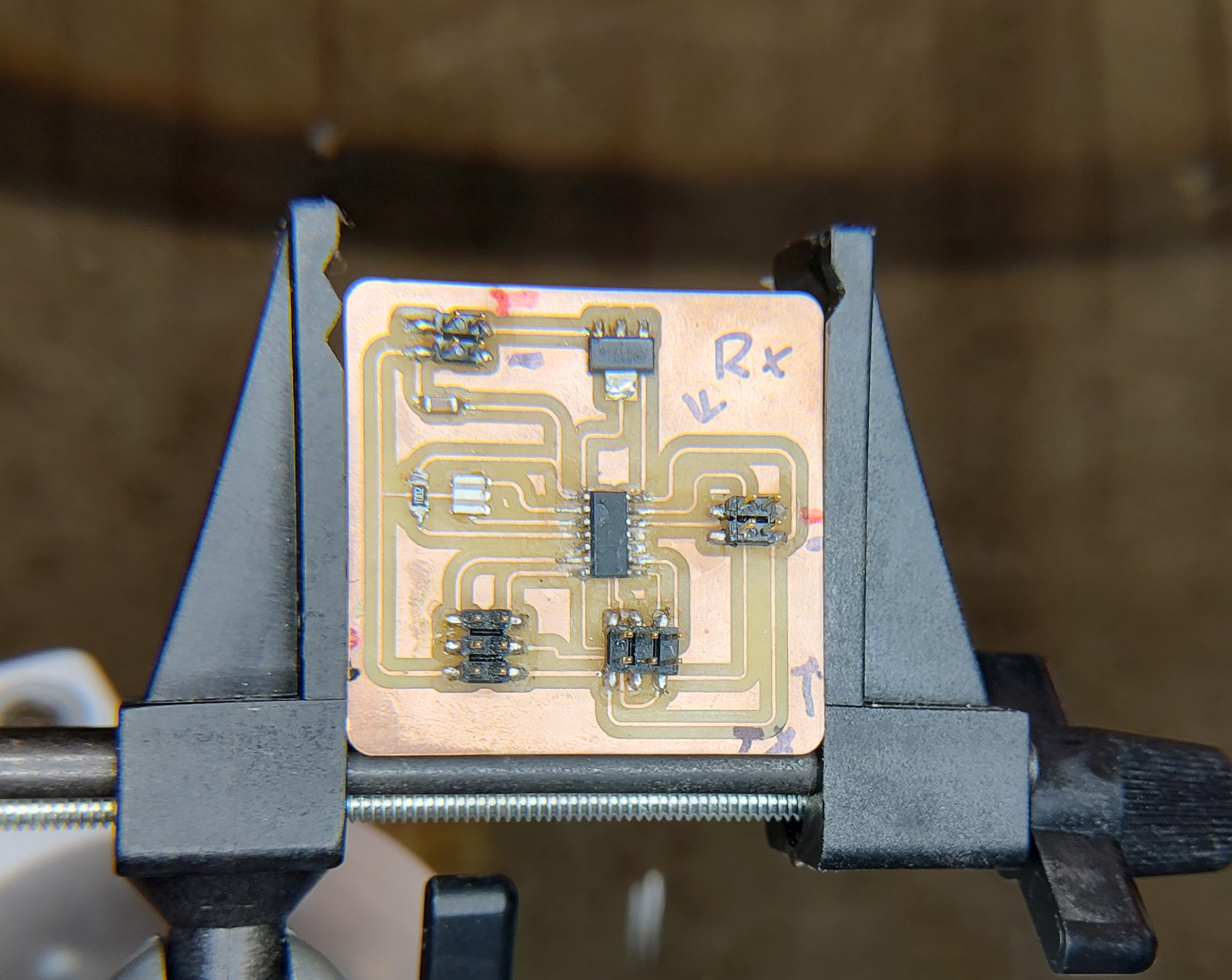
Image: Servo PCB.
- The second one is a PCB that controls a Bipolar Stepper Motor.
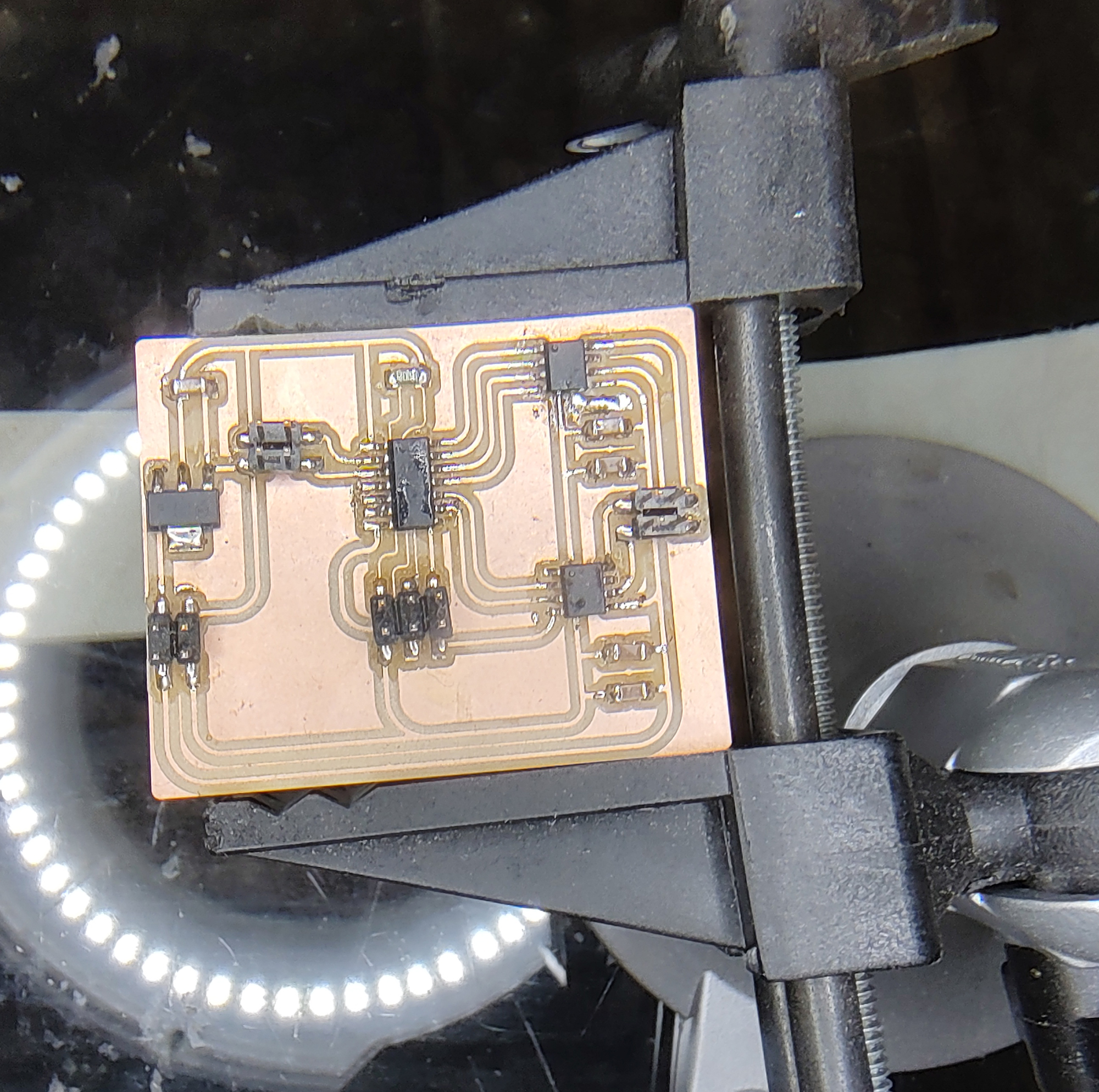
Image: Stepper Bipolar PCB.
- The third and final one is a PCB that controls a Unipolar Stepper Motor.
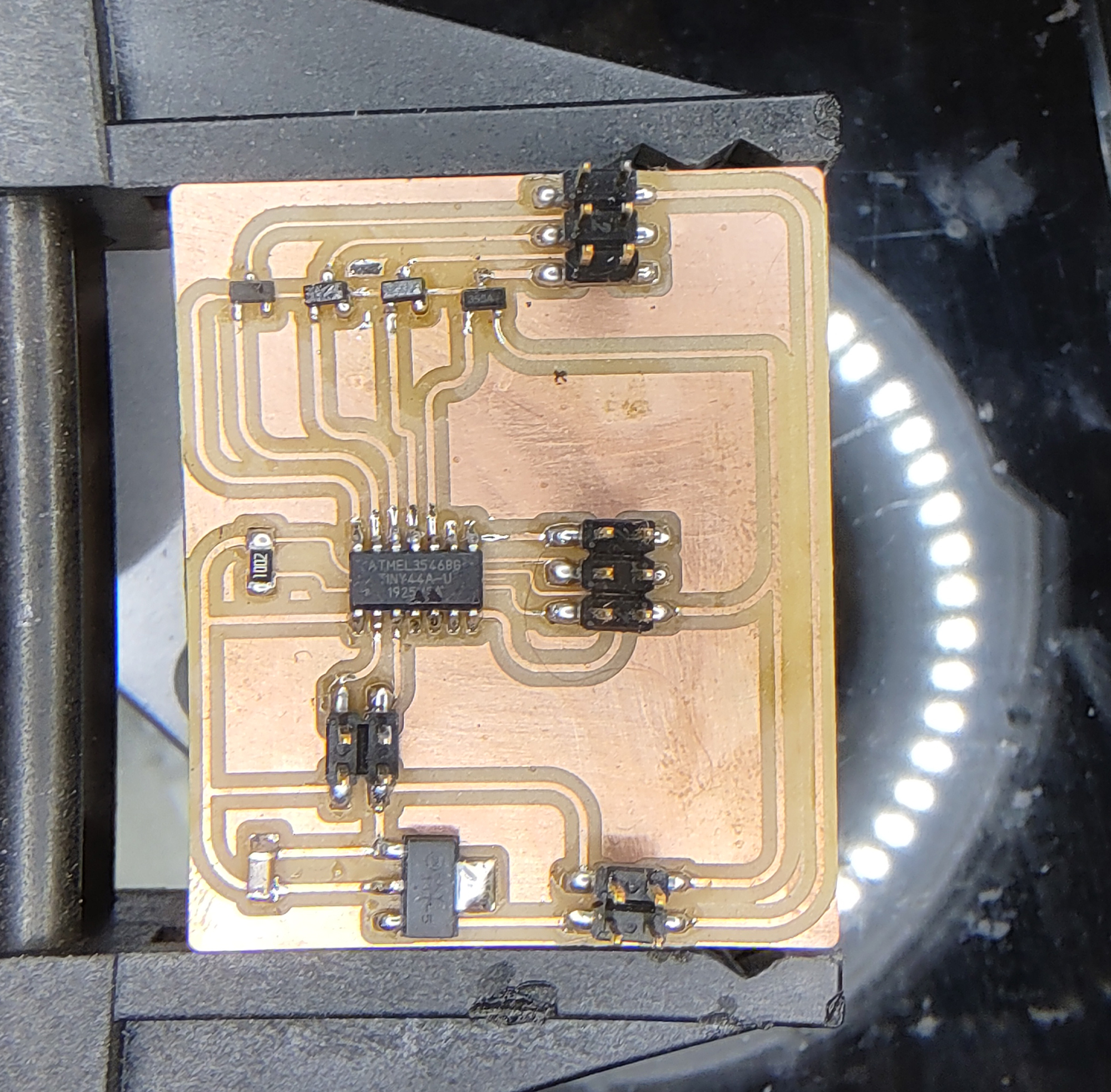
Image: Stepper Unipolar PCB.
For the final project, and in this cycle of development, I will work with the Servos.
What materials and components will be used?
For Object Design:
The Cylinder is made of 15 and 18 millimeters plywood boards. The pieces are cut in the Shopbot CNC machine available at the Fab Lab. The cut is done accounting for a Kerf of 2mm, keeping male parts in real size and increasing the female parts to compensate for the Kerf. The pieces are fixed in place using screws, bolts, nuts and washers. This configuration allows for assembling and disassembling the modules easily, and as required.
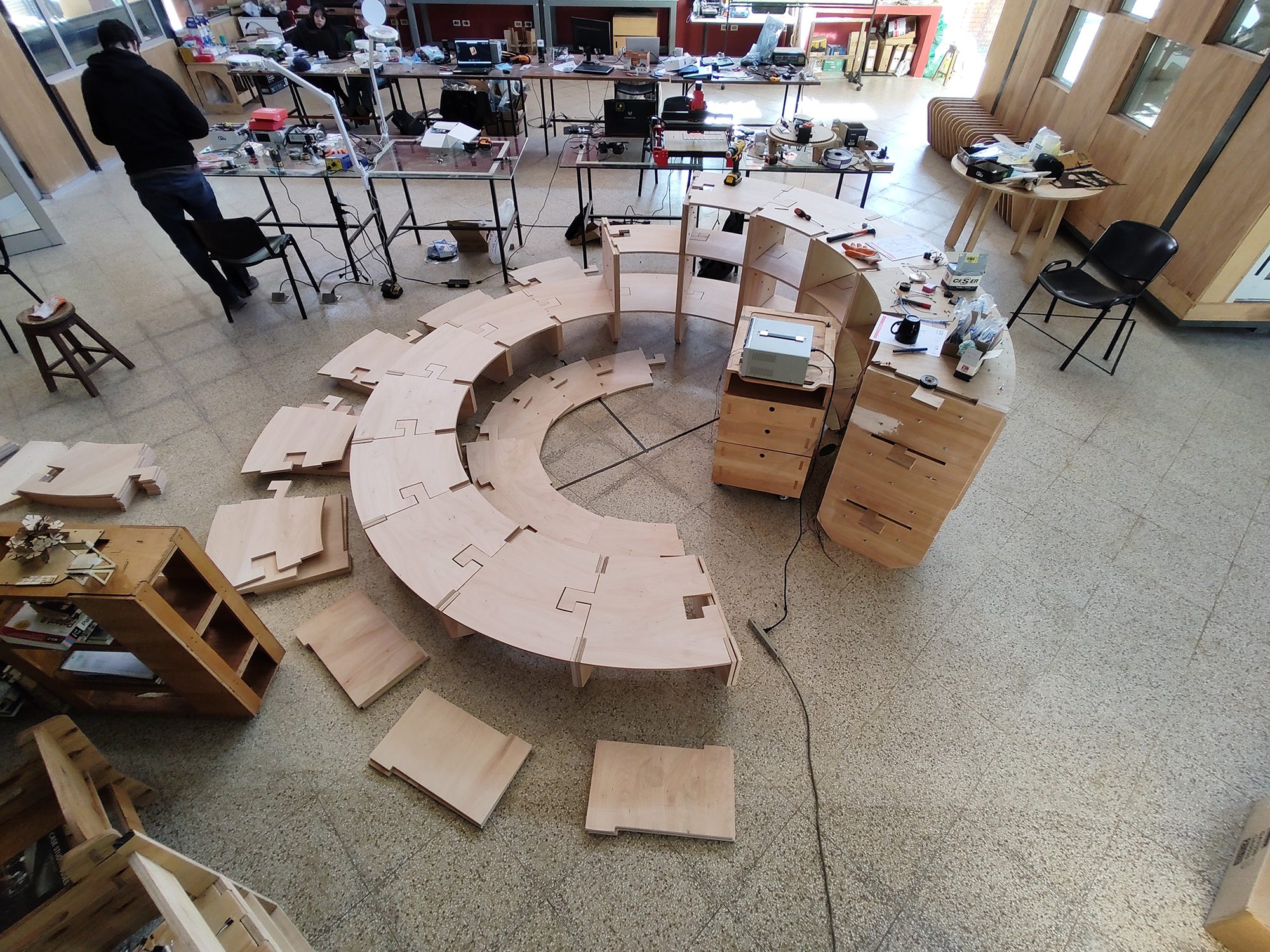
Image: plywood pieces ready to assemble.
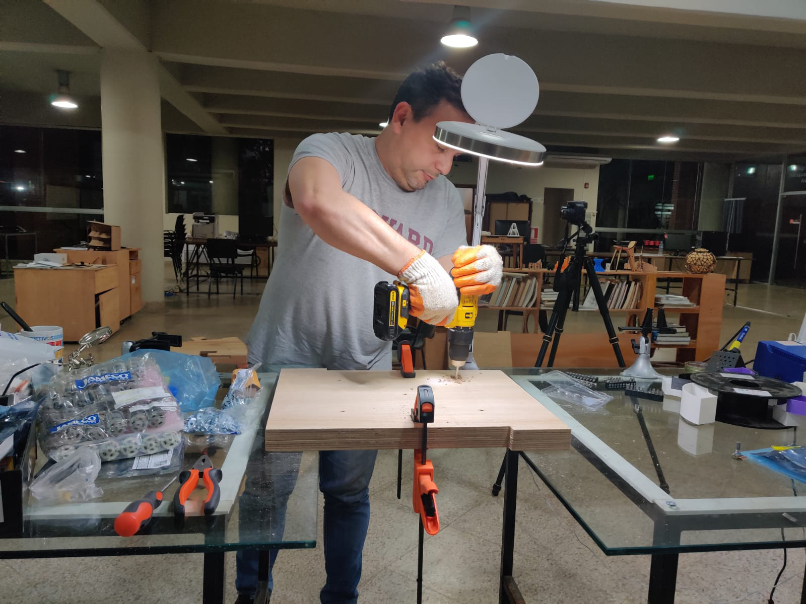
Image: assembly process.
For Mechanical Design:
- Holder for the servos: 3d printed pieces, in black PLA.
- Holder for the bearings: 3d printed pieces, in black PLA
- Transition and connection between motor or bearing and the blinds: 3d printed pieces in black PLA.
- The blinds: 9 mm MDF boards, cutted with laser cutter.
- The transmission rods: acrylic sheets, cutted with a laser cutter.
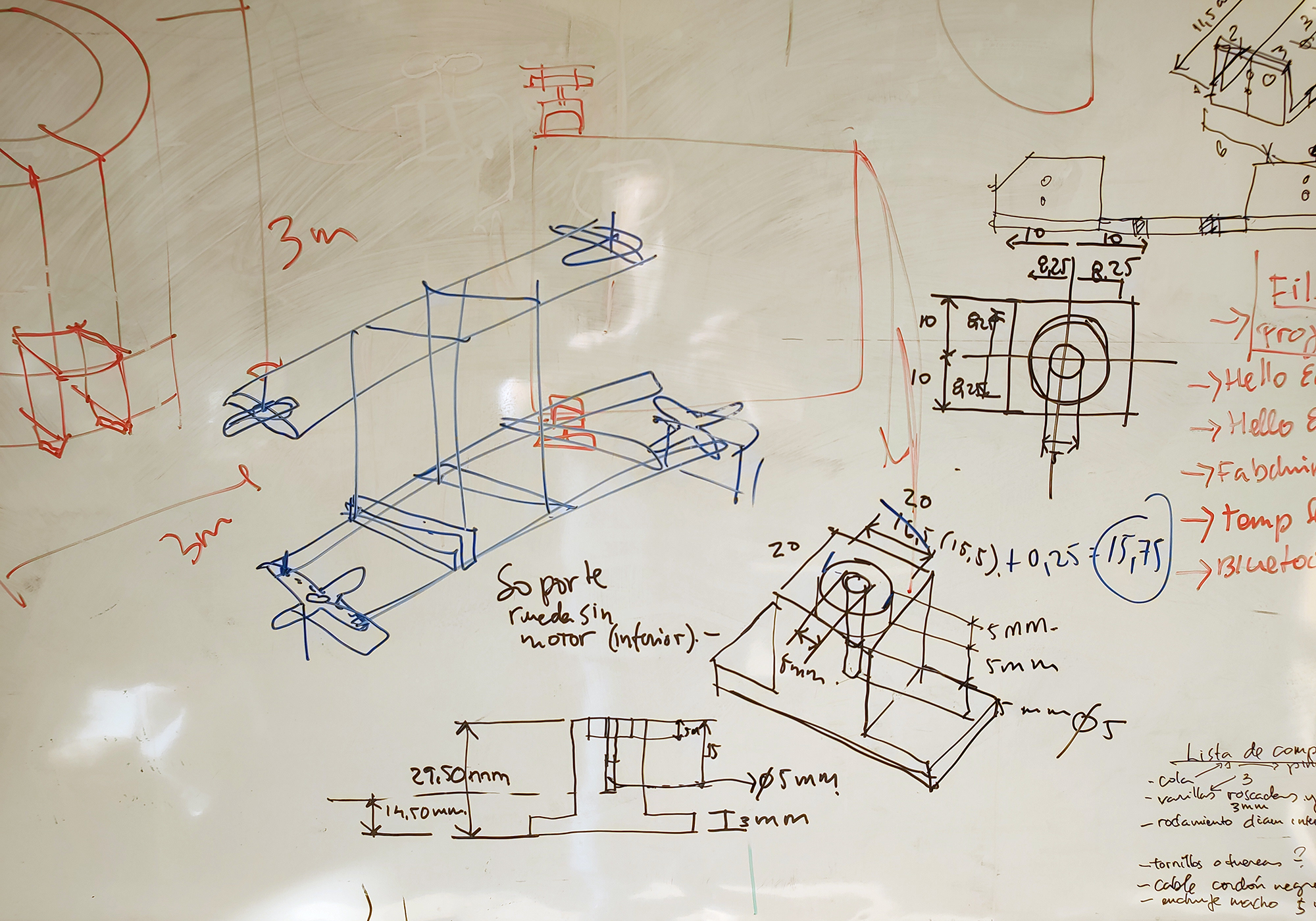
Image: Diagram - holder piece for bearings
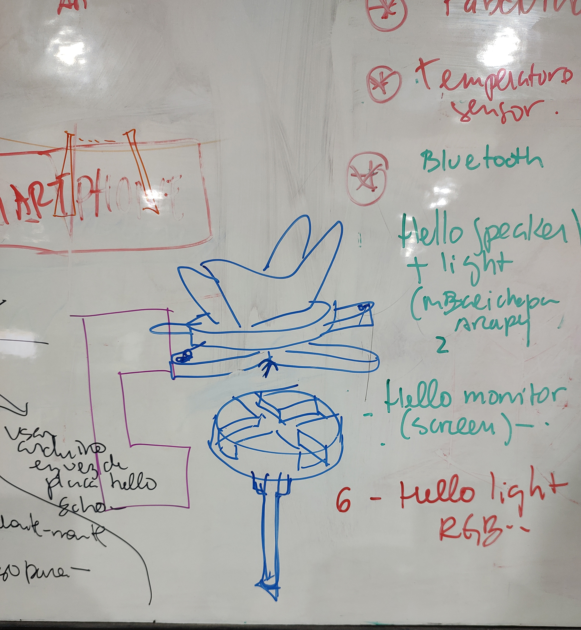
Image: Diagram - axis for bearing and transitional piece to blind
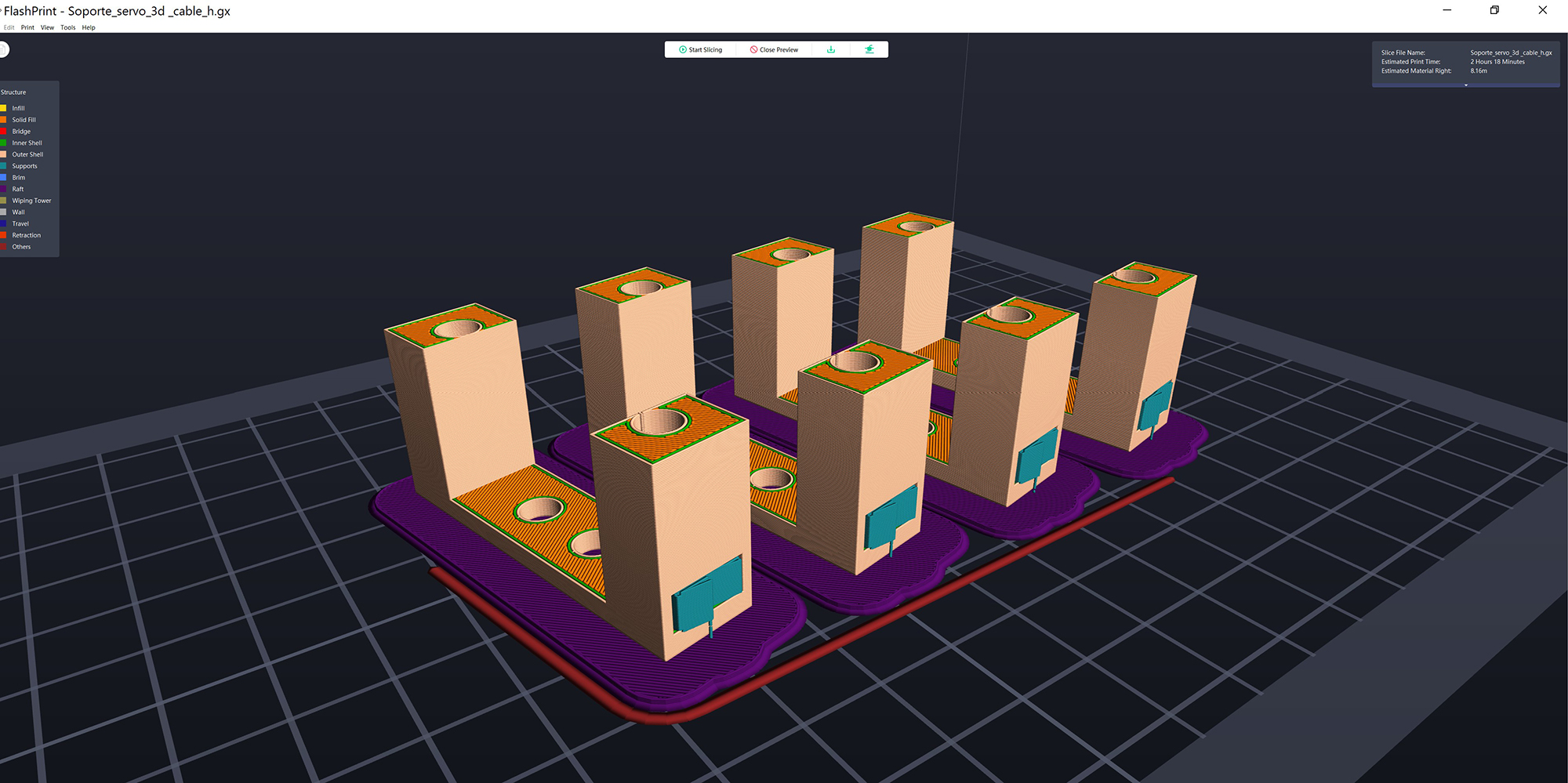
Image: 3d printing file - servo support
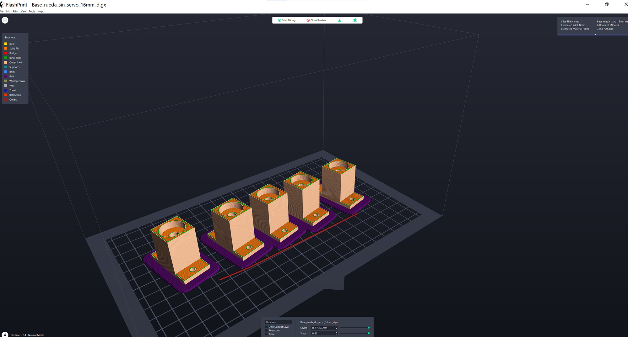
Image: 3d printing file - bearings support
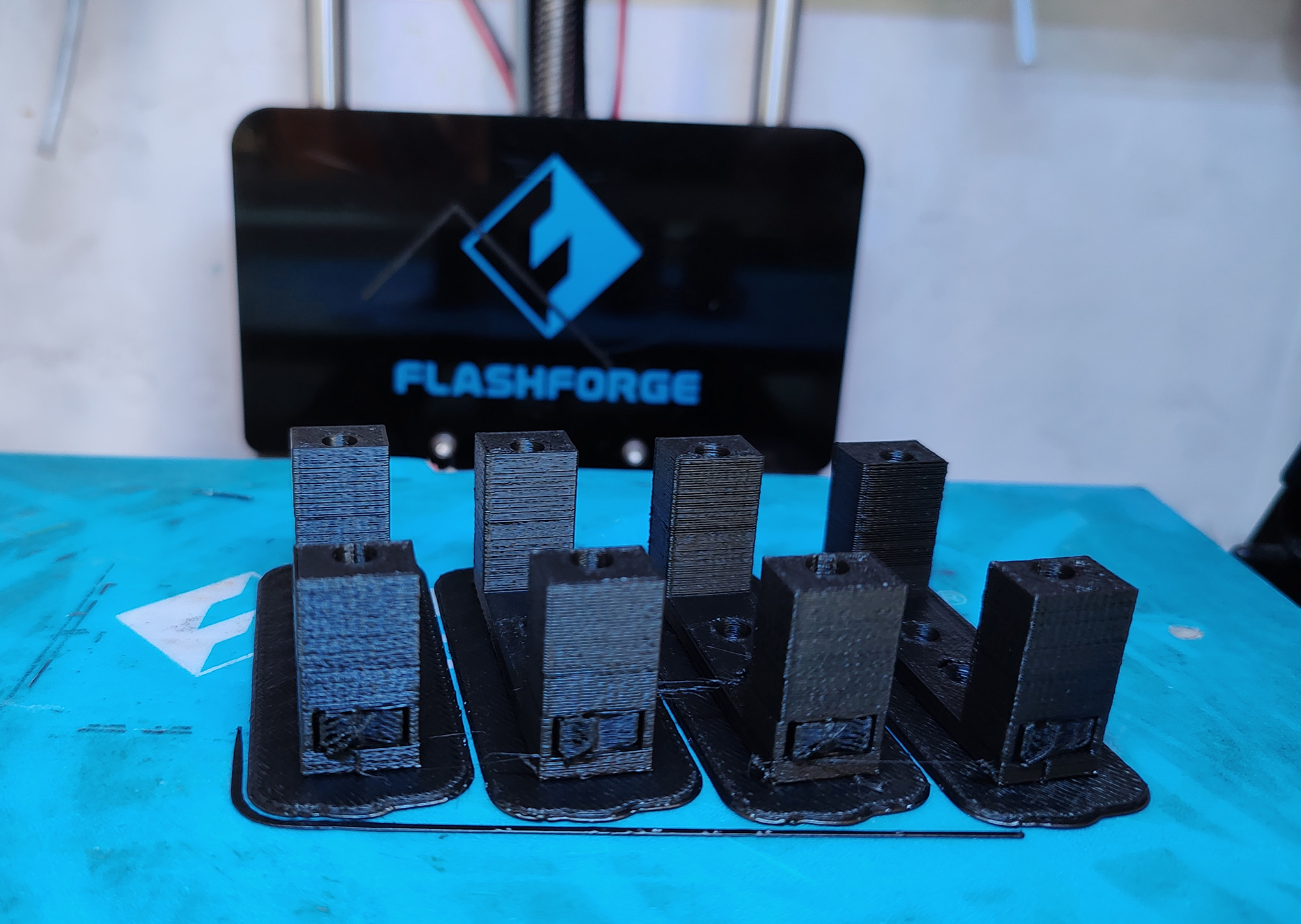
Image: 3d printed Servo support
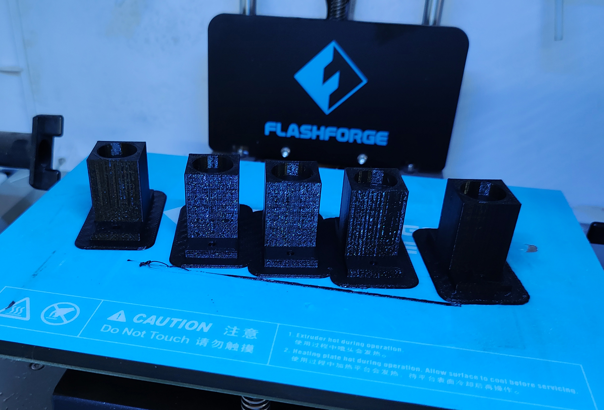
Image: 3d printed bearing support
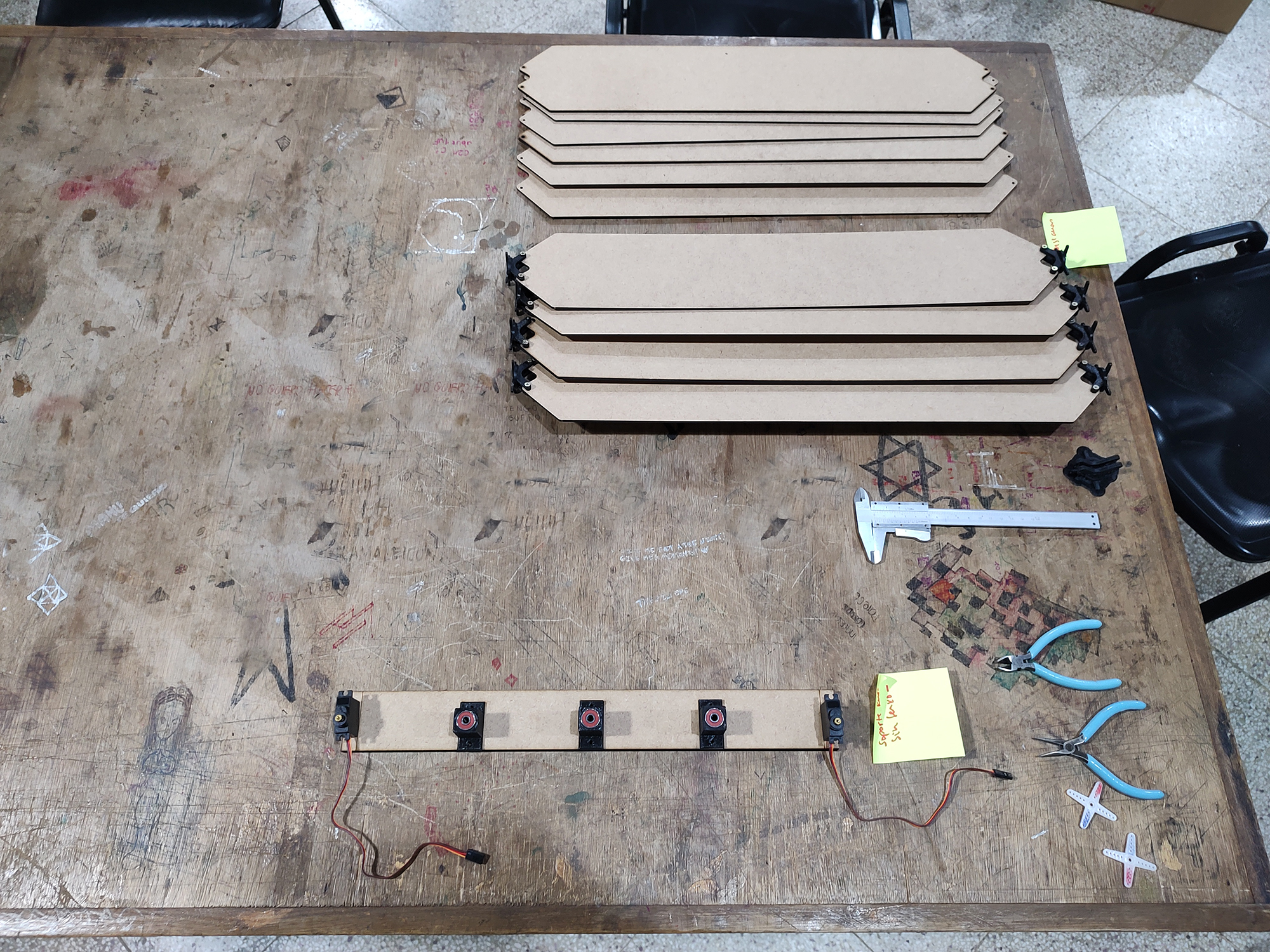
Image: lasser cutted blinds and 3d printed pieces, ready to assemble
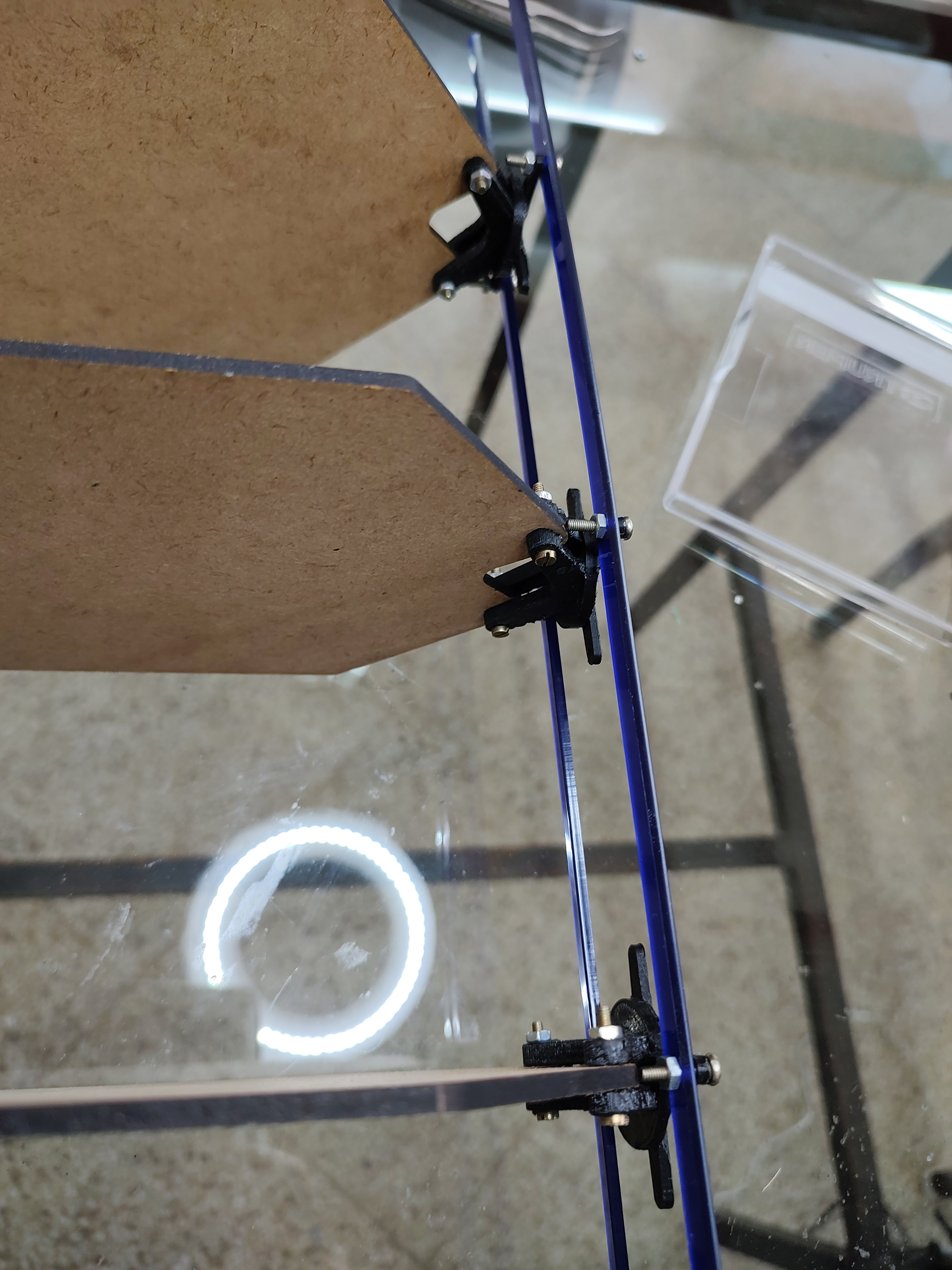
Image: assembly process, acrilic rods
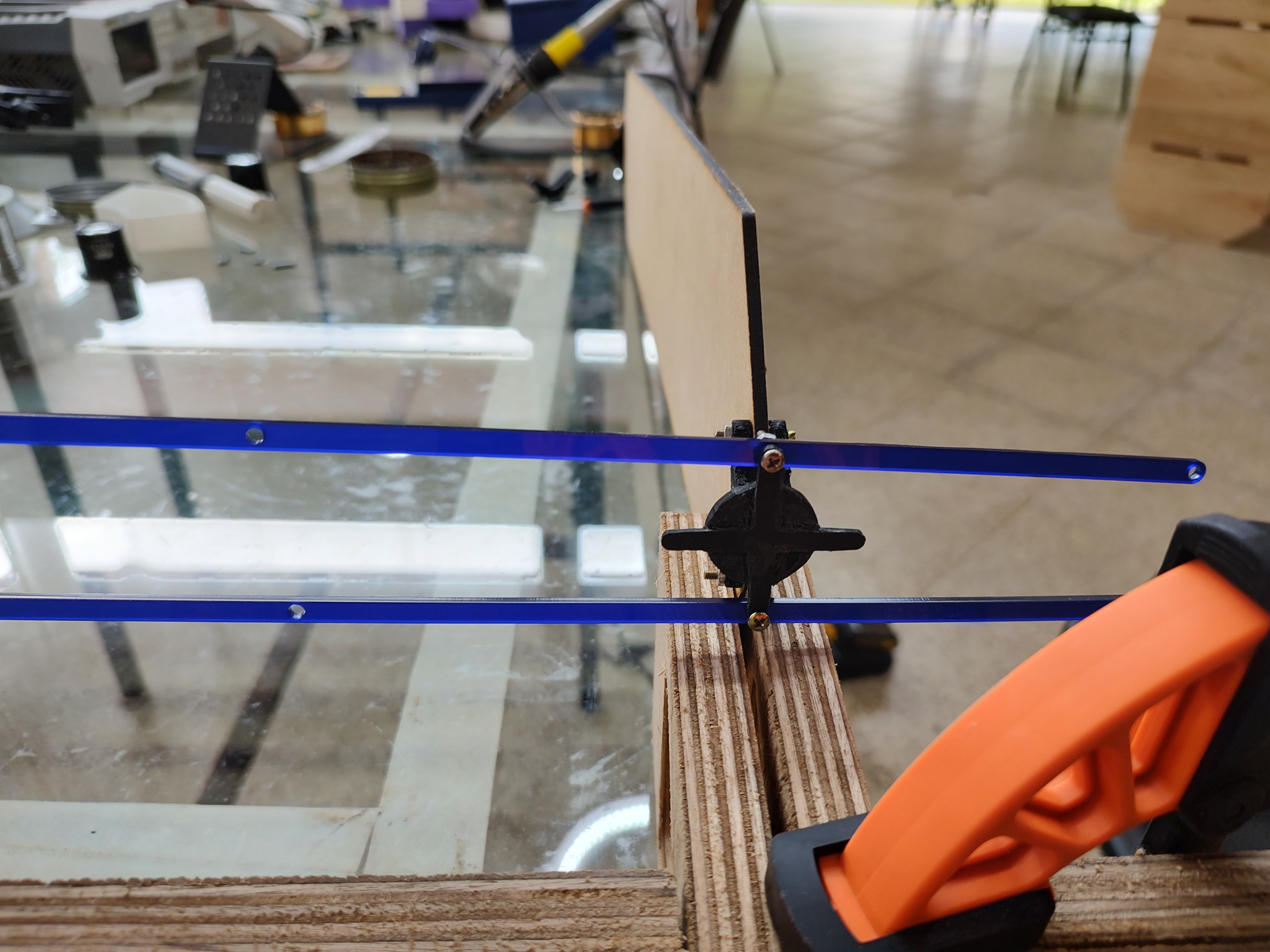
Image: lasser cutted acrilic rods
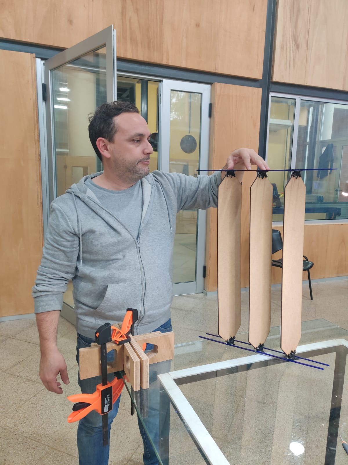
Image: assembly process, blinds and transmission acrilic rods
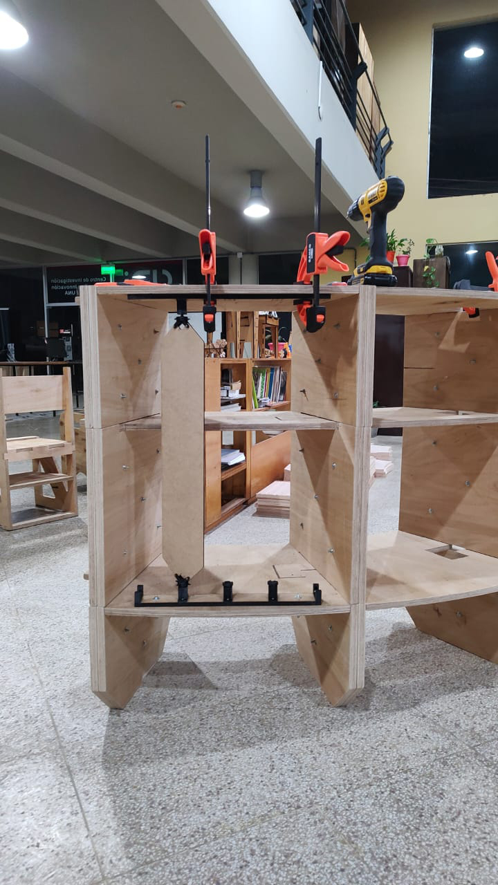
Image: assembling blinds in the module
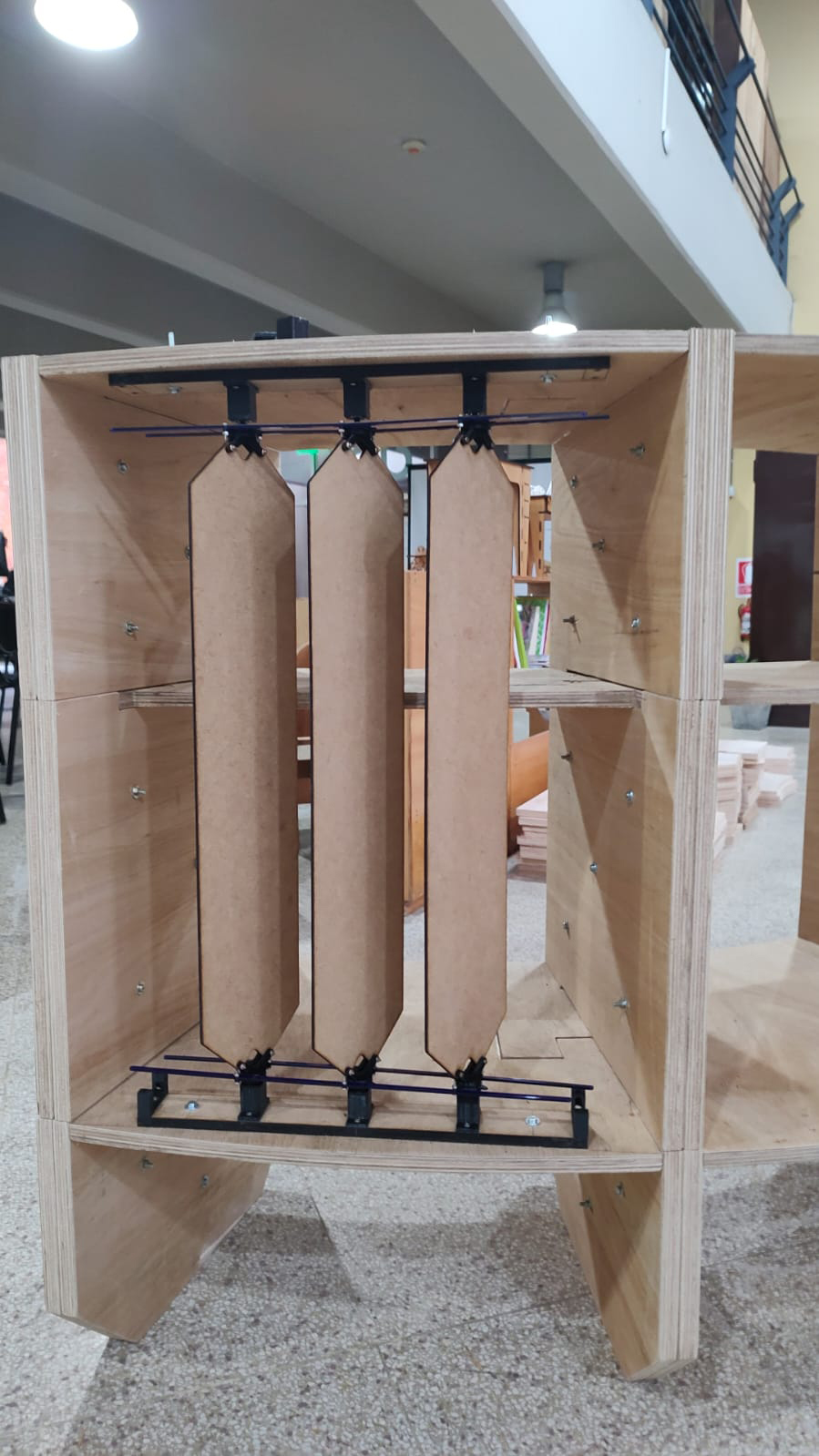
Image: testing 3 blinds in the module
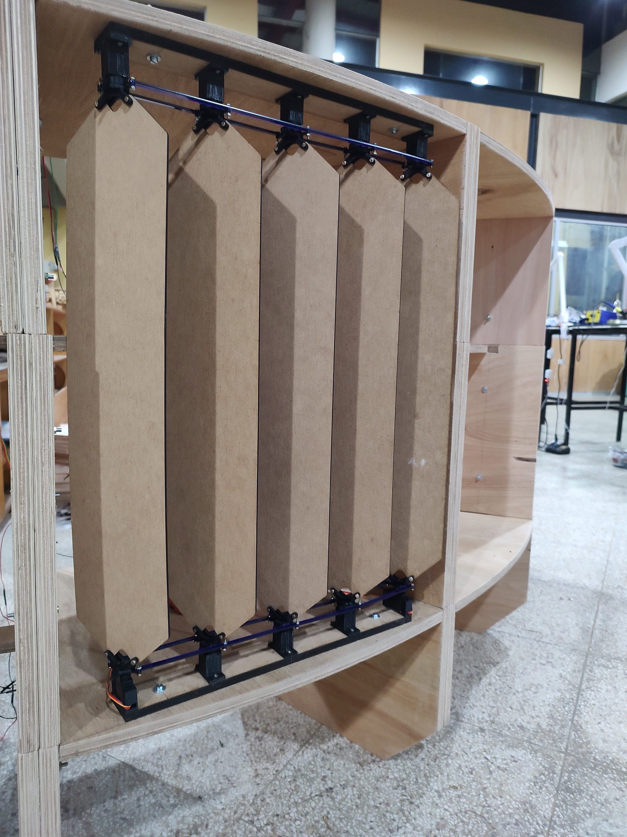
Image: testing blinds and rods in the module
Video: mechanical test of motion for the blinds
Video: Blinds in motion controlled by servo PCB and Light sensor PCB
For Electronics Design:
All PCBs were designed by me, based on the “Hello Echo” boards available at the Fab Academy website.
Where will the materiasl come from?
All materials are part of the Lab’s inventory, except for screws, bolts, nuts, washers and bearings. These small metallic parts were all bought in local hardware stores.
How much will they cost?
- Metallic parts (screws, bolts, nuts, washers and bearings): 150 US$.
- 3d printing filament: 30 US$.
- MDF Boards (9 mm, 15 mm and 18 mm) : 300 US$
- Electronic components: 20 US$
- Total 500 US$
Costs refers only to materials. Machine time and labor costs are not included.
What parts and systems will be made?
- All parts of the Cylinder were made in the lab using the CNC Shopbot Alpha.
- All PCBs were machined in the lab using the Roland MDX 540.
- All Blinds cutted in the JQ laser cutter .
- All transition pieces between bearings, servos and blinds, were made in the lab, using Flashforge Dreamer 3d printers, except for the transmission rods which were cutted in the lab.
What processes will be used?
- Object design and mechanical design using 2d and 3d CAD.
- 3d Printing. (additive)
- CNC Cutting. (subtractive)
- Laser Cutting. (subtractive)
- Electronics Design.
- Networking and communication (using serial).
What questions need to be answered?
In this cycle of development:
- Can I actually assemble everything and make it work?
- Can I obtain all required parts in the lab and the local market?
In a future cycle of development (working with farmer’s cooperatives, after Fab Academy)
- Will this be a contribution for farmers?
- What can be improved in the design with the orientation of the farmers.
How will it be evaluated?
In this cycle of development:
- Completing a fully functioning prototype of the Shadowhouse.
In the next cycle of development:
- Establishing an association with farmers cooperatives to work together in the improvement of the first version of the working prototype.
The Checklist
Your project should incorporate 2D and 3D design,
Object Design, Mechanical Design, Electronics Design, involves both 2d and 3d drawings developed at Rhino, Fusion and Eagle. Conceptual bidimensional and tridimensional sketches were developed in graph paper and boards.
Additive and subtractive fabrication processes,
As previously mentioned both additive and subtractive fabrication processes were used. - 3D Printing. (additive) - holders for bearings and servos, support for blinds. - CNC Cutting. (subtractive) - All major MDF pieces for the cylinder. - Laser Cutting. (subtractive) - Blinds, transmission rods cutted in Acrylic.
Electronics design and production,
- Customized PCB board for controlling Servos.
- Customized PCB for light sensor based on phototransistor.
Embedded microcontroller interfacing and programming,
- Firmware developed to translate light levels into specific positions or the servo, using PWM and serial communication.
System integration and packaging
- Object Design was carefully developed to produce an ergonomic and visually cohesive product.
Where possible, you should make rather than buy the parts of your project.
- Everything was designed and built in the lab, with the exception of small metal pieces: screws, bolts, nuts, washers and bearings.
Projects can be separate or joint, but need to show individual mastery of the skills, and be independently operable
- It was an independent project developed from templates provided in the course and based on previous experiences developed at the Fab Lab Network.