14. Networking and communications
Week 14 / April 27
Individual assignment:
Design, build, and connect wired or wireless node(s) with network or bus addresses
Group assignment:
Send a message between two projects
Indvidual assingment - Connecting the servo board to a second board which is able to control it.
Related to the final project. First steps in order to connect the servo to the Main Board and light Sensor.
For this week I connected the Servo PCB developed at Week 11 with the “Hello echo light button” PCB and the light sensor developed at Week 13. I will form two simple neworks with these three elements, using serial communication.
What I did.
My full exploration went through the following stages:
1) Calibration of the servo motors: in order to know values of Pulse Width Modulation (PWM) - The objective is to determine values of PWM that correspond to three key positions of the servo: 0 degrees, 90 degrees and 180 degrees. This firmware will be applied to the “Servo controlling PCB” (based on the “Hello Servo PCB”)
2) Write and test a “Time signal” firmware: that transmits the states 0, 1, 2. These three states will later be related to positions 0 degrees, 90 degrees and 170 degrees. This time signal will be uploaded in the “Hello echo light button board”.
3) Write and test a firmware: that moves the servo to known PWM and positions, according to three States, following the table below:
| PWM | Angle | State |
|---|---|---|
| 6 | 0 | 0 |
| 22 | 90 | 1 |
| 36 | 170 | 2 |
This firmware will be based on serial communication, and on a first phase the states 0, 1, and 2 will be loaded manually on the monitor of Arduino IDE. This firmware will be applied to the “Servo controlling PCB” (based on the “Hello Servo PCB”)
4) Form a first network: linking the “Hello echo light button board” with the “Servo controlling PCB”. The servo will move periodically, to positions 0,1 and 2 according to the input received from the “Hello echo light button board”.
5) Develop a serial-based firmware for the “Light Sensor PCB”: the phototransistor produces an analog signal from 0 to 1024. This range will be initially divided also in three states of 0, 1 and 2.
| Analog Signal from phototransistor | Observation: | state | angle |
|---|---|---|---|
| 0 - 340 | More light, lower the number | 0 | 0 |
| 341 - 682 | 1 | 90 | |
| 683 - 1024 | Less light, higher the number | 2 | 170 |
6) Form a second network, linking the “Light Sensor PCB” with the “Servo Controlling PCB”: The servo will move inversely in reference to light levels. More light, the servo will go to “Closed” position (170 degrees) and with less light, the servo will go to “Open” or “Full Open” (90 degrees and 0 degrees, respectivelly). This is the basic network necessary for my final project.
I will now develop each one of these phases.
1) Calibration of the servo motors: (again)
Really calibrate input to movement for the two types of servo we have in the lab. (May 8th) As reported in the Week 10, outputs, I developed a long exploration to know the inputs related to movement in the servos. The synthesis of my findings using the oscilloscope is the following:
For the HobbyKing HK-15138 Servo (Big Servo):
Standard Analog Servo 4.3Kg / 0.17Sec / 38G
0o = 6
170o = 36
Does not complete 180o of rotation
For the HobbyKing HK-15178 Servo (Small Servo):
Standard Analog Servo 1.4kg / 0.10sec / 10g
0o = 7 180o = 37 Does complete 180o of rotation
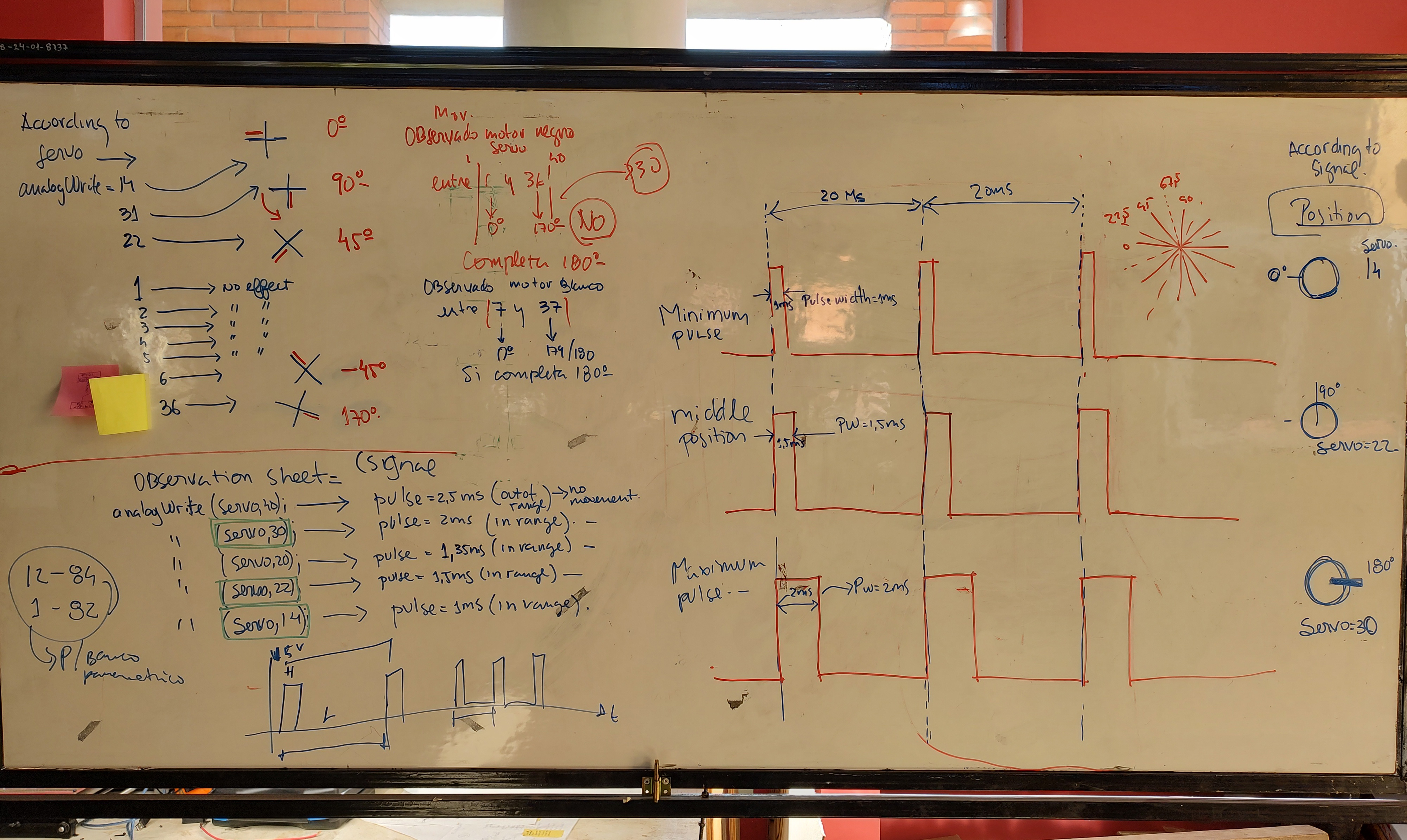
Calibrating the Servos according to PWM
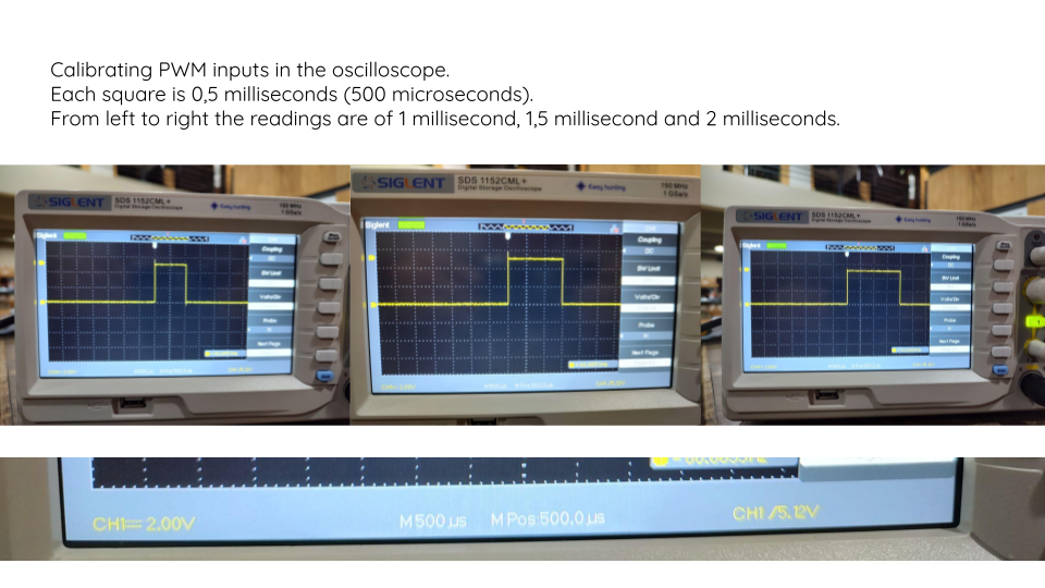
Calibrating the Servos - reading the oscilloscope
This is the firmware I developed to calibrate PWM relative to position:
#include <SoftwareSerial.h>

int rx = 1;    //Declares the RX 1 pin 3
int tx = 0;    //Declares the TX 2 pin 4

SoftwareSerial mySerial(rx, tx);  //Setting up the RX/TX pins as a SoftwareSerial

char buttonState = '0';//Declares the character that represents the virtual button current state
char lastButtonState = '0'; //Declares the character that represents the virtual button last state

int servoPin = 6;     //Declares the pin where the Servo is already attached
int servoPinb = 7;     //Declares the pin where the Servo is already attached
int dutycycle = 6;
int dutycycleb = 6;
void setup(){
  mySerial.begin(4800);       //Start the serial communication and select the its speed that deppends of the frequency that it will be program the attiny

  pinMode(servoPin, OUTPUT);      //Configures the LED pin as an output
  pinMode(servoPinb, OUTPUT);      //Configures the LED pin as an output


}

void loop(){
analogWrite(servoPin, 6);     //Moves to 0 degrees
analogWrite(servoPinb, 6);     //Moves to 0 degrees
delay (3000);
analogWrite(servoPin, 22);     //Moves to 90 degrees
analogWrite(servoPinb, 22);     //Moves to 90 degrees
delay (3000);
analogWrite(servoPin, 36);     //Moves to 170 degrees
analogWrite(servoPinb, 36);     //Moves to 170 degrees
delay (3000);
}
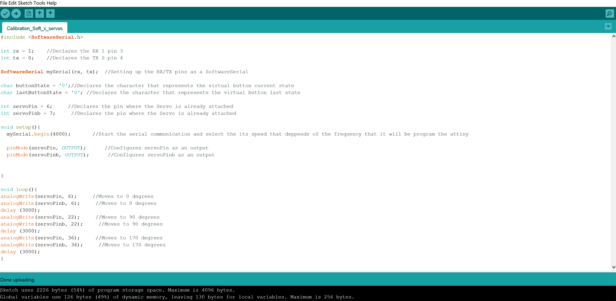
Code for calibrating Servo with PWM in Arduino IDE
Video of Calibrated Servo moving according to PWM
2) Write and test a “Time signal” firmware:
The objective here was to generate a code in arduino to send a time signal from a different board, and to make the servo board to move regularly, based on the input received.
For this we develop a simple program to be loaded in a second board. The objective of this code would be to correlate time periods with positions of the servo. This is another spiral in the electronics & software development of my final project. The second board used here is again the modest Hello echo light button board, which will be then substituted by the Main Board, a FabDuino Board. The code developed is the following
test_0_1_2_for_servo_motor_from_echo_light_time_signal

#include <SoftwareSerial.h>

int rx = 2;    //Declares the RX 1 pin 3
int tx = 1;    //Declares the TX 2 pin 4

SoftwareSerial mySerial(rx, tx);  //Setting up the RX/TX pins as a SoftwareSerial

void setup(){
  mySerial.begin(4800);       //Start the serial communication and select the its speed that deppends of the frequency that it will be program the attiny
}

void loop() {
  //mySerial.println("alo_alo");
  mySerial.println('0');
  delay(5000);
  mySerial.println('1');
  delay(5000);
  mySerial.println('2');
  delay(5000);
}
I used Arduino IDE to test and load the code. I used the Attiny 44 programmer to program the code in the Servo_Board. We checked the proper functioning of the code by serial communication via FTDI cable, receiving the “0”, “1” and “2” texts in the defined time interval.
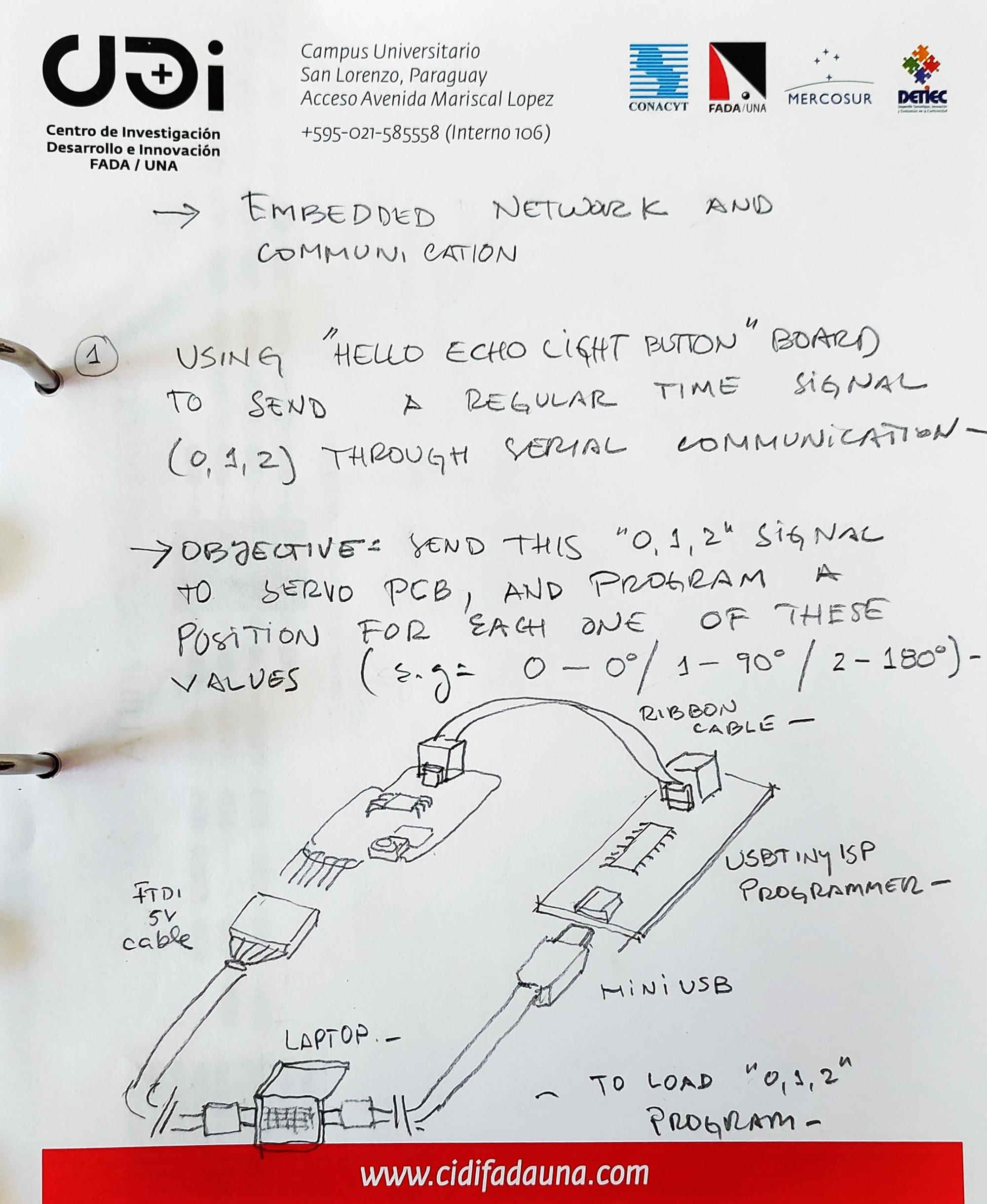
Diagram for 0,1,2 programming process
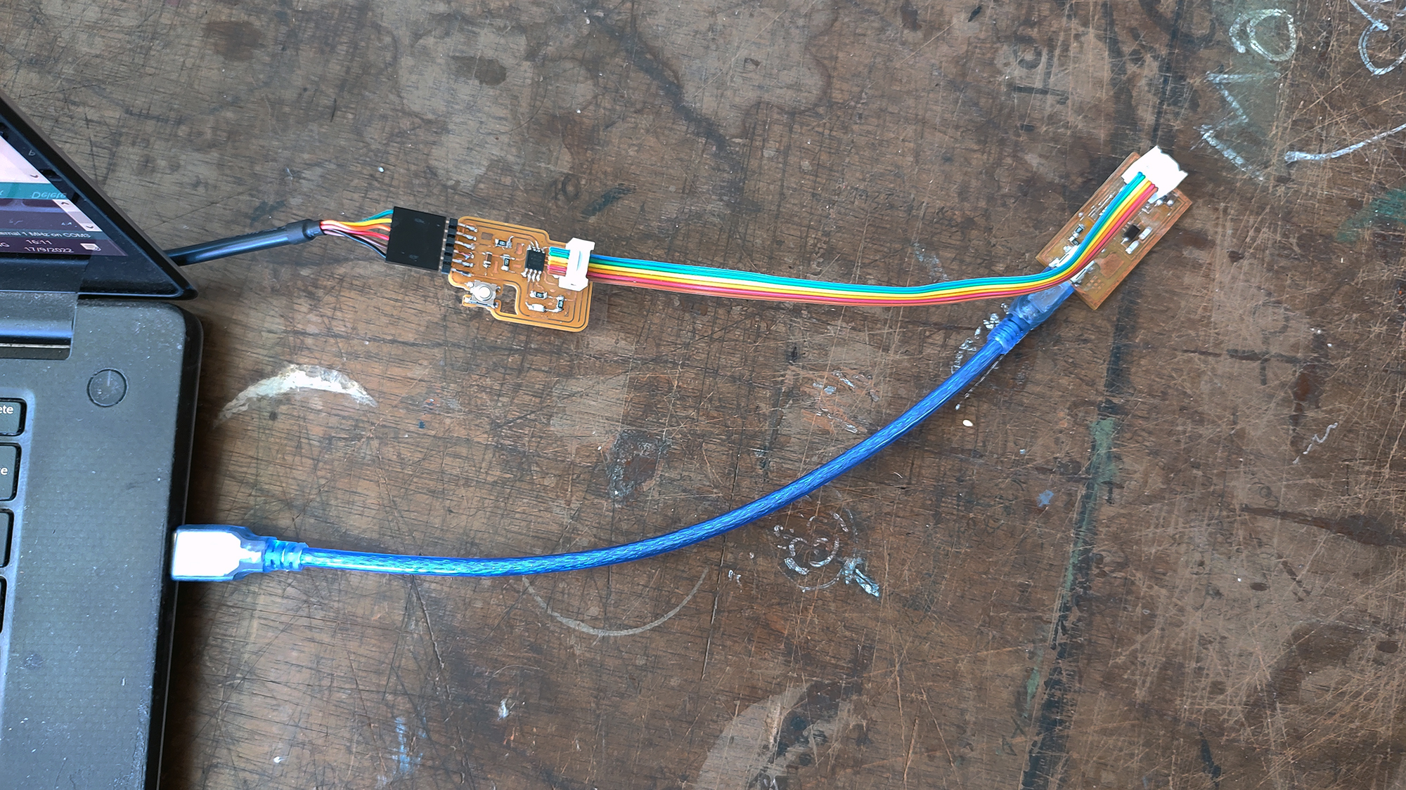
Programmer and hello echo world button PCB
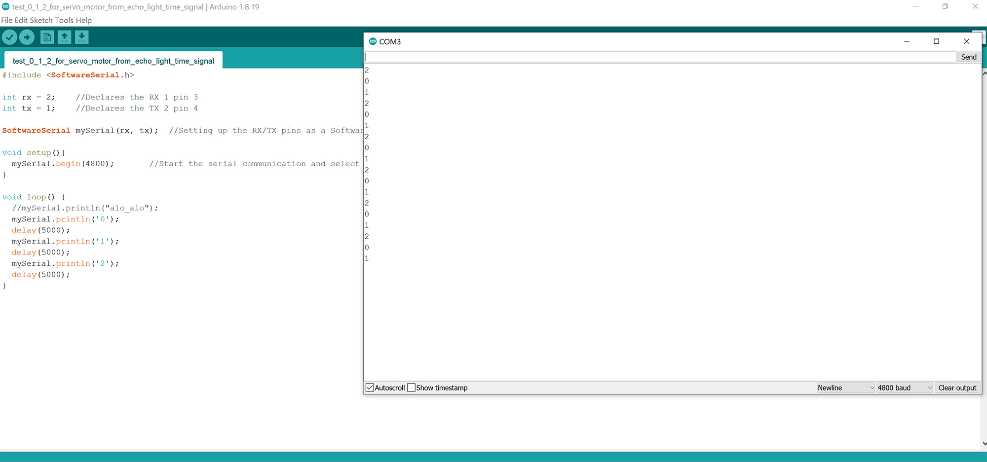
Seeing results in the monitor of Arduino IDE
3) Write and test a firmware to control servos according to PWM:
Generate a code in arduino for moving the servo to three angular positions (0o, 90o, and 170o) Working with Abdón I looked for several options to develop a code that could control the position of the servos. Finally we developed the following code:
#include <SoftwareSerial.h>

int rx = 0;    //Declares the RX 1 pin 3
int tx = 1;    //Declares the TX 2 pin 4

SoftwareSerial mySerial(rx, tx);  //Setting up the RX/TX pins as a SoftwareSerial

char buttonState = '0';//Declares the character that represents the virtual button current state
char lastButtonState = '0'; //Declares the character that represents the virtual button last state

int servoPin = 7;     //Declares the pin where the Servo is already attached
int dutycycle = 6;
void setup(){
  mySerial.begin(4800);       //Start the serial communication and select the its speed that deppends of the frequency that it will be program the attiny

  pinMode(servoPin, OUTPUT);      //Configures the LED pin as an output

}

void loop() {
  //mySerial.println("probando");

  buttonState = mySerial.read();    //Reads the message a "1" or a "0" from the command line

  if (buttonState != lastButtonState) {   //Checks if there exist a change in the virtual button state

    if (buttonState == '0') {         // Condition For Motor ON

      mySerial.println("Servo IS 0 deg \r");         //Prints in the screen the actual state
      dutycycle = 6;
    }
    else if (buttonState == '1'){      // Condition For Motor OFF

      mySerial.println("Servo IS 90 deg \r");         //Prints in the screen the actual state
      dutycycle = 20;
    }
    else if (buttonState == '2'){      // Condition For Motor OFF

      mySerial.println("Servo IS 180 deg \r");         //Prints in the screen the actual state
      dutycycle = 36;
    }
    analogWrite(servoPin, dutycycle);     //Turns ON the indicator LED


  }

  lastButtonState = buttonState;        //Sets the current state as a last state

}
I used Arduino IDE to test and load the code. I used the Attiny 44 programmer to program the code in the Servo_Board. We checked the proper functioning of the code by two separate modes of verification:
a) serial communication via FTDI cable, where we received the feedback texts corresponding to the instructions given to the board, and
b) the motion of the servo itself.
4) Form a first network:
Everything was now ready to form the first network and… Nothing worked! (debug, debug, debug)
After successfully completing the two parts of the network project, we connected the Hello_Servo board and the Hello_echo_light_button and …. nothing worked. The servo did move a couple of times (providing evidence that some form of communication was going on between the two boards) and then it stop. We took the following steps for debbugging:
- We verified again the proper functioning of the two programmed boards, and tested the connection again. Same result. - Hypothesis: there is a problem with one of the two boards (separately) - Discarded.
- We assessed the possibility that the frequency was incorrect. The serial number communication messages showed us that definitely, 1 mhz was the proper frequency, as any other frequency used would provide no results in the monitor window, or random results. - Hypothesis: the frequency is incorrect - Discarded.
- We assessed the possibility that baud was incorrect. Changed from 9600 to 4800. Reprogrammed the two boards. Each worked well independently. Connected, again it did not work. - Hypothesis: the baud is incorrect - Discarded.
- We assessed the possibility that the Attiny 45 and Attiny 44 could not work properly together, due to some hardware limitation. Thus we decided to use an Arduino Board instead of the Hello_echo_light_button board. We programmed and used the Arduino board and it worked well. In this process we provided energy to the servo not through the Hello_Servo board but through the Arduino. - Hypothesis: Attiny 45 and 44 do not work properly together - Result: Partial confirmation - The Arduino board improved the performance of the network. The motor moved correctly.
- The following question was, in which way was arduino better? Was it the expanded logical capacity of the Arduino board? Or was it the fact that we provided energy to the servo independently which led to the improved result?
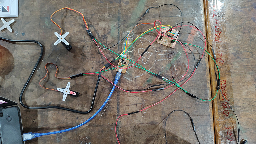
- To confirm or disconfirm this, we developed a simple test: we provided the data from the Hello_echo_light_button board to the Hello_servo_board, and energy to the motor through the Arduino board.
Finally!!
It worked perfectly. By successive tests we could conclude and prove that the problem was that the energy supply to the motor was in some way negatively affecting the data transfer between the boards, or between the Hello_servo and the motor. For the final project the conclusion is that we will provide energy to the motors independently.
Programmer and hello echo world button PCB
Video of First network working
5) Develop a serial-based firmware for the “Light Sensor PCB”:
Phase five of this project was to develop one more firmware. This is the firmware required to relate input analog light signals ranging from 0 to 1024, to codified states designed with numbers 0,1 and 2. Each one of these three numbers is then related to one of the servo positions of 0, 90 and 170 degrees, respectively. This firmware contains all the basic definitions necessary for the final project.
Please see the code below:
// This example code is in the public domain

#include <SoftwareSerial.h>

int rx = 0;    //Declares the RX 1 pin 3
int tx = 2;    //Declares the TX to be PB2
int sensorPin = A3; // Declares input sensor
int sensorValue;
int limitOne = 340;
int limitTwo = 682;


SoftwareSerial mySerial(rx, tx);  //Setting up the RX/TX pins as a SoftwareSerial


void setup() {

mySerial.begin(4800);

}

void loop() {

  sensorValue = analogRead(sensorPin);

  if (sensorValue <=limitOne){
    mySerial.println('0');
  }
  else if (sensorValue >limitOne && sensorValue <=limitTwo){
     mySerial.println('1');
  }
  else if (sensorValue >limitTwo){
    mySerial.println('2');
  }


  delay(1000);

}

// reference : https://www.arduino.cc/en/Tutorial/AnalogReadSerial
6) Form a second network, linking the “Light Sensor PCB” with the “Servo Controlling PCB”:
The final phase of the exercise was to form a second network between the “Light Sensor PCB” and the “Servo Controlling PCB” The network worked properly from the first attempt. Please see the result in the video below:
Video of the second network working:
What I learned this week.
- Debug patiently. Record every step in order to discard hypotheses that have been disproven.
- Making something work is different than knowing why it works. Try always to isolate WHY it works or it doesn’t work
- Making different parts of a network to work properly is different than making the network work. As you integrate pieces, new complexities and unforeseen problems arise. Be ready for the fact that each step of the spiral may need to be debugged.
Design and fabrication Files here:
Shadow Servo
Shadow Light Sensor
Link to the lab’s webpage:
See the collective network assignement we did at CIDi