9. Embedded programming
Week 08 / March 16
This week’s assignment:
Group assignment:
- compare the performance and development workflows for other architectures
Individual assignment:
- read the data sheet for your microcontroller
- use your programmer to program your board to do something
- extra credit: try other programming languages and development environments
Mba’éichapa Arapy
(Hello World in Guaraní)
(I wrote a code, which contains a text translated to morse code, to be “played” byt the board and then read by a computer)
The full cycle would be:
-
Computer (coding)
-
Board
-
Output (light and sound)
-
Computer (to recognize the sounds produced by the board and translate back from Morse to text).
For this week, I focused on testing the developed program using:
- An Arduino UNO Board and,
- Also programming the hello-echo board I have previously developed.
Research on the Datasheet for the microcontrollers:
ATmega328P
The ATmega328P is the microcontroller at the center of Arduino UNO.
Image 1: Atmega328P Datasheet
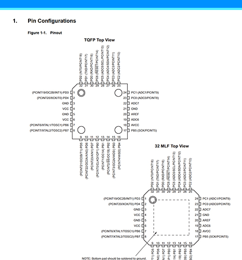
Image 2: Atmega328P Pinout
Attiny45
The ATtiny45 is the microcontroller used in the hello-echo-light-button board.
Image 3: Attiny45 Datasheet
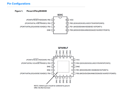
Image 4: Attiny45 Pinout
The Arduino IDE iteration
I had the idea of using our hello-echo world to “talk back” at us, using Morse Code. Furthermore, I wanted to speak Guaraní, one of the native languages of paraguay, and its second oficial idiom, alongside Spanish.
Learning about morse code:
It was clear that morse code is composed of a succession of dots and dashes. Thus, the first step was to understand the “rhythm” of morse code. After looking on several web pages, I found out the following structure:
dot=one time unit
dash = three time units.
delay after dot and dash (in the same letter)=one time unit.
delay after each full letter=three time units
delay after each word= seven time units
Following that, I had to transform the text “Mba’éichapa Arapy” (Hello World) to morse. It’s a relatively long text, - much longer than the usual S.O.S. used as first iteration text - but some of the words repeated letters (vowels specially), helping abbreviate the process.
Finally, we had to close the circle and make a computer “hear” the message and translate it back from either sound or light to text again.
Working with my instructor Abdón Troche, we tried several apps and devices that claimed to decode light or sound to inteligible text again, but none of them worked.
We added an additional (and more powerful) led light to the standard arduino light. We also added a resistance and a piezo to add audio (in synchrony with the lights). None of this brought any positive results. The reading of the morse code both in audio and with lights rendered only meaningless characters as result.
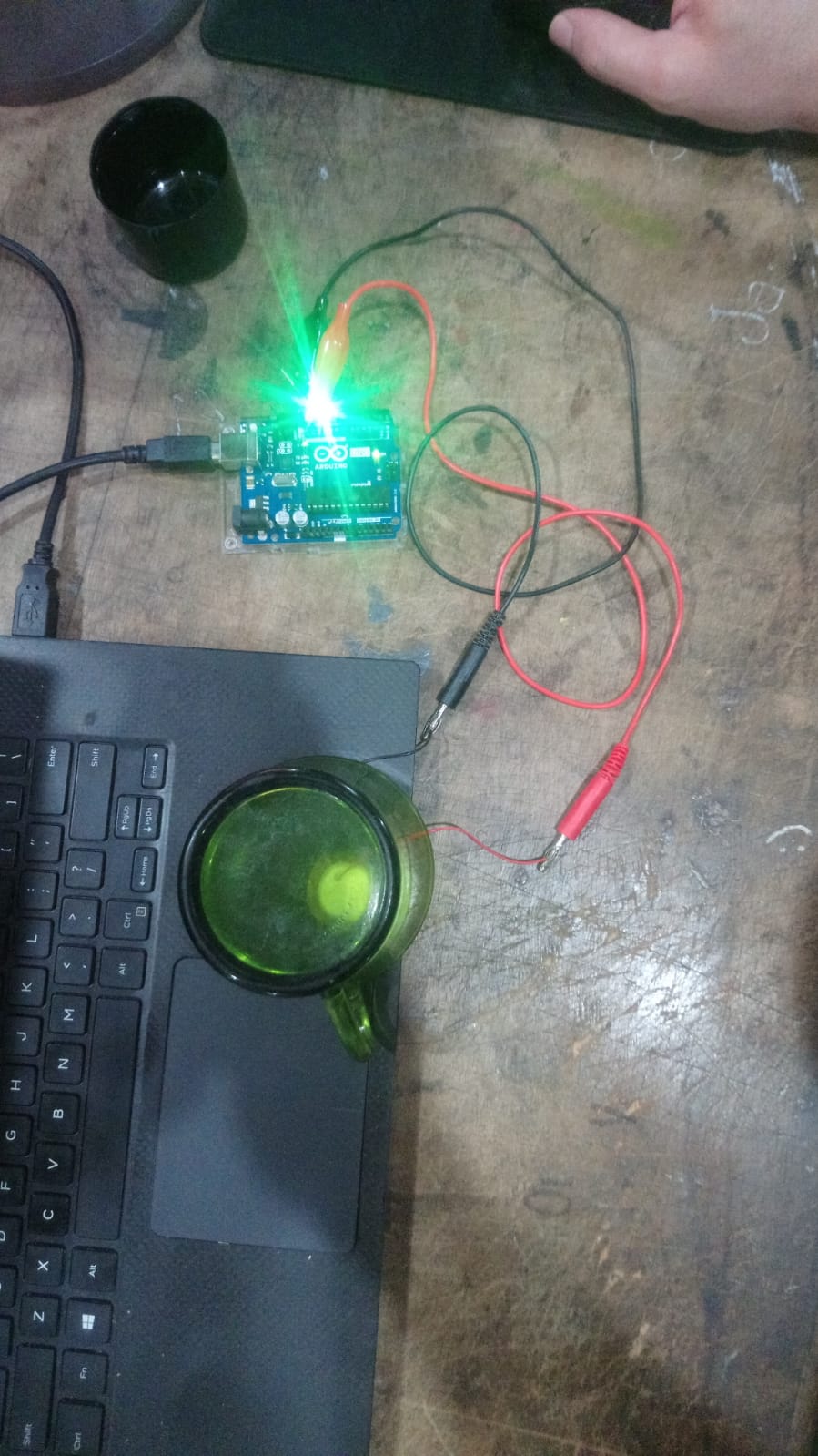 Image 5: Arduino board and aditional led, with piezo and tea cup amplifier
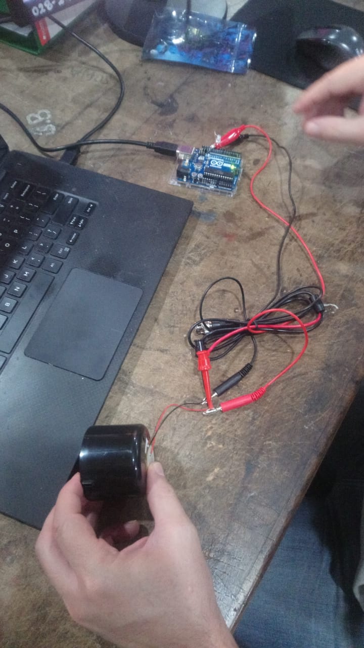 Image 6: Piezo and spray cap amplifier
Apps tried:
Finally, we found a viable option in the Morse Code Adaptive Audio Decoder, from Morse Code World
We had to change the frequency and also the tempo of the sound in order to make the code clearer. Morse Code Translator was very useful to give us an adequate reference framework of how actual morse code sounded like.
After several iterations changing the duration of the time for dots, and also the frequency, in order to change the sound, we obtained a positive result. The base time unit is the dot, and what proved to work correctly was a dot equal to 80 miliseconds. Adjusting for this value, the website was able to decode the audio back to text in guaraní. We could do this several times.
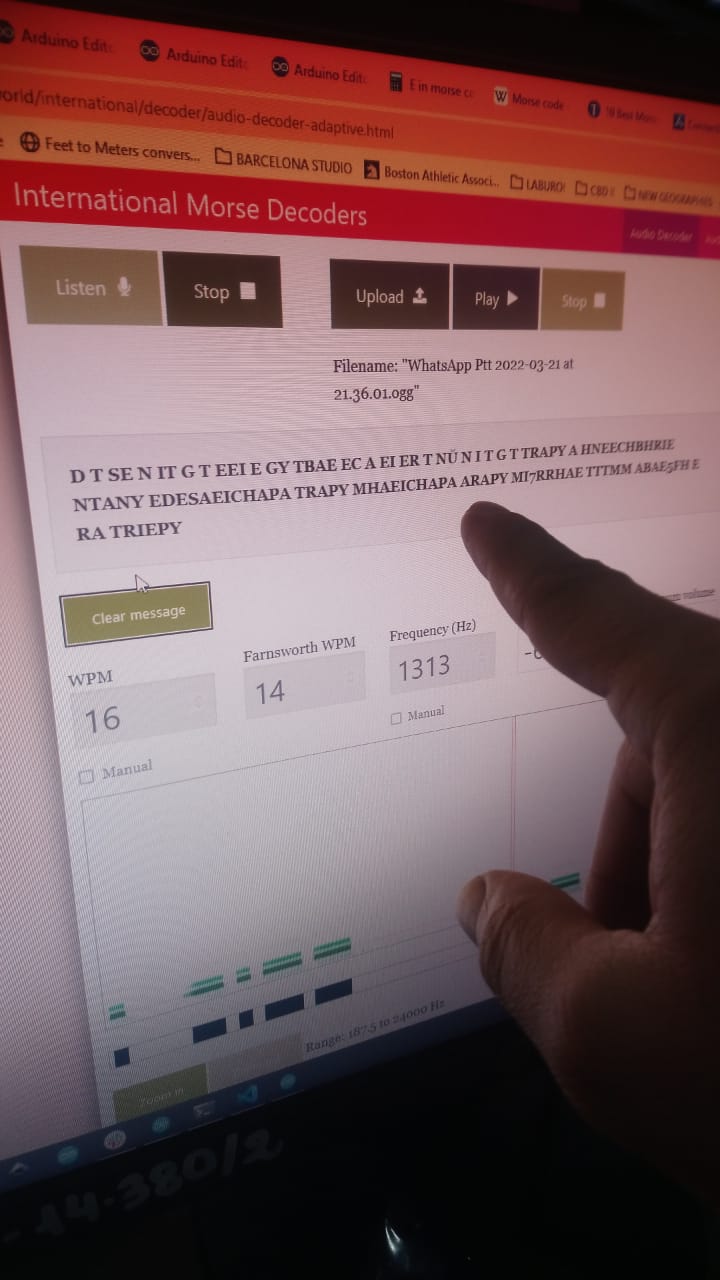 Image 7: First good result
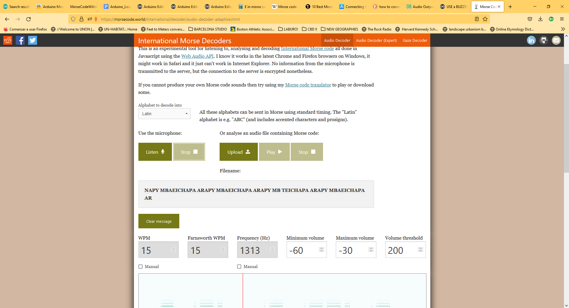
Image 8: confirmation of good results
!So cool to see the computer understanding Guarani morse code!
The Hello-Echo-Light-Button iteration:
After we finished the iteration on the Arduino UNO, we loaded the same program on the PCB I have previously developed, the Hello-Echo-Light-Button, which runs on an Attiny 45. The morse code worked perfectly, but only with the LED light. In a further iteration I want to develop a board that combines both sound and light.
Relevant information about the microcontrollers:
Reading the datasheets I could find out the capabilities related to each Pin. This Pin layout and function is called the Pinout. For the Attiny 45 the pinout is the following:
- Physical Pin 1: (PCINT5/RESET/ADC0/dW) PB5
- Physical Pin 2: (PCINT3/XTAL1/OC1B/ADC3) PB3
- Physical Pin 3: (PCINT4/XTAL2/CLKO/OC1B/ADC2) PB4
- Physical Pin 4: GND
- Physical Pin 5: PB0 (MOSI/DI/SDA/AIN0/OC0A/OC1A/AREF/PCINT0)
- Physical Pin 6: PB1 (MISO/DO/AIN1/OC0B/OC1A/PCINT
- Physical Pin 7: PB2 (SCK/USCK/SCL/ADC1/T0/INT0/PCINT2
- Physical Pin 8: VCC
I am an architect and urban designer, and thus, prior to Fab Academy I had no contact whatsoever with Electronics or programming, other than perhaps, to use Rhino and Grasshopper for parametric and generative design. Thus the entire aspect of getting familiarized with all the details about each microcontroller is totally new for me. Thanks to the careful observation of the datasheets I could learn that each Pin has a certain number of possible capabilities or capacities, and some of them are configurable and other are not.
I learned that in the case of the Attiny 45 (and its brothers in the series of the Attiny family, the Attiny 25 and 85), this is a Surface Mount Device (SMD) microcontroller with 8 physical pins. There is also a quad flat no-lead package (QFN) for the Attiny 25, 45, 85 series but we do not have it in the inventory of Fab Lab CIDi.Thus, all the observations here developed refer to the ATtiny 45 SMD.
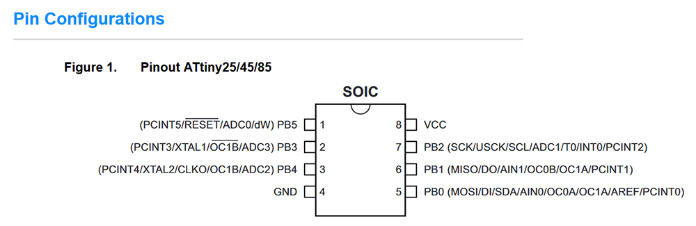 Image 9: Pinout of Attiny45
The numbering of the physical pins begins in the upper left corner and develops counterclockwise (CCW). The only other pattern that is easily recognizable is that GND (Ground, negative) and VCC (Common Collector Voltage; the positive supply voltage for an integrated circuit) are in diagonal and opposite to each other, using Pins Number 4 and Number 8, respectively.
As for the order in which of the remaining physical pins are codified as B Port, there is no clear discernible pattern. The B port designations are related with the internal design of the microcontroller, which, of course, cannot be seen as it is contained and sealed within the package and such design is microscopic.
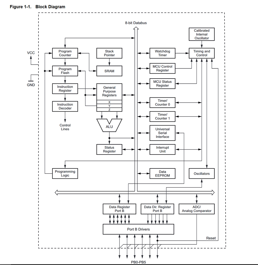 Image 10: Block diagram
A full description of the functions of each B Port is available in the datasheet. In it we can see for instance, that the PB0 is set as Main Out Secondary In (MOSI) and PB1 is set as Main In Secondary Out (MISO). Thus, PB0 could be used to send data to another device, and PB1, to receive data from another device.
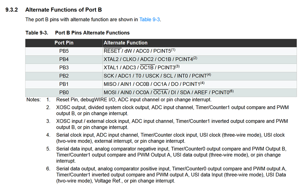 Image 11: Alternate functions of Port B
What it was useful for you in order to program the board:
I used the Arduino IDE (Integrated Development Environment), in combination with my programmer, the Yodaboard, a USBTinyISP device. Thus, I also needed to know the Arduino Pinout for Arduino IDE. This is due to the fact that the codifications of the pins are different in Arduino IDE and in the Physical pinout of the microcontroller.
For instance, in this exercise I developed a morse code program in the Arduino IDE. For this, it is necessary to “tell” the LED to work or not, according to specific time intervals. The functioning of the LED is controlled by the “digitalWrite High” (on) and “digitalWrite Low” (off) commands. To be able to communicate this to the microcontroller, you need to locate:
- Which is the physical Pin that provides energy to the LED (in my case 2),
- Which is its PB Code (PB3),
- and what is the equivalent designation of that Pin in Arduino IDE (3 or A3).
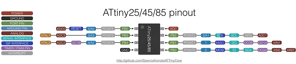 Image 12: Arduino IDE pinout for ATtiny 45
Describe the programming process you used in your PCB ( not arduino ).
Tools> Arduino IDE in combination with Yodaboard, a USBTinyISP programmer.
- Open Arduino IDE.
- Assign Board as ATtiny 25/45/85
- Assign processor as ATtiny 45
- Set clock at 1Mhz
- I looked for a template of code for only-light morse
dot=one time unit (500 miliseconds)
dash = three time units. (1500 milisenconds)
delay after dot and dash (in the same letter)=two time units. (1000 miliseconds)
delay after each full letter= two time units (1000 miliseconds)
delay after each word= four time units (4000 miliseconds)
- I addapted this code template, according to the adequate timing that we tested on the arduino iteration. This is the final setting of dots and dashes:
dot=one time unit (80 miliseconds)
dash = three time units. (240 milisenconds)
delay after dot and dash (in the same letter)=one time unit. (80 miliseconds)
delay after each full letter=three time units (240 miliseconds)
delay after each word= seven time units (560 miliseconds)
- With this adjustment, the code worked correctly.
Which library did you use in the Arduino IDE for programming your PCB ? Describe how you installed it .
All libraries in Arduino IDE are installed using the structure #include , for instance:
#include<SoftwareSerial.h>
I used SoftwareSerial.h extensively in my work throughout the Fab Academy, and in my final project, to connect the servos and shades to the Phototransistor PCB. But in this exercise of Morse Code, I did not include or use any libraries. I worked purely with functions.
Firmware Files here:
Guarani Morse Code - for Arduino - light and sound
Guarani Morse Code - for Hello-Echo-Light-Button - only light
Link to the lab’s webpage:
Please see the notes about performance and development workflows here:
CIDi’s Embedded programming notes