13. Input Devices
Week 13 / April 20
This week’s assignment:
Group assignment:
- Probe an input device’s analog levels and digital signals
Reading Analog levels:
Reading Digital levels:
Individual assignment:
- Measure something: add a sensor to a microcontroller board that you have designed and read it
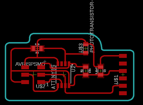
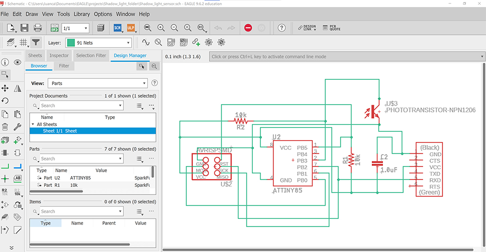
Light Sensor.
Related to the final project, control of shades within Shadowhouse.
What I did:
I designed a board, based on the Hello Servo Attiny45 example. In the overall design of my final project, this board is responsible to collect information about light levels and report to the Primary Board, in order to move the shutters within Shadowhouse. The motion will be controlled by a Secondary Board which will activate the servos.
This was a very special week. It was the first time after two years of pandemic that we had a proper commencement ceremony here at the university. This had a rather funny effect on my working attire while developing the phototransistor board.
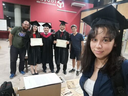
From left to wright, Abdón, Silvia Arévalos, myself, Tomás Lopez, Doc Jorge Roig, and Silvia Lugo
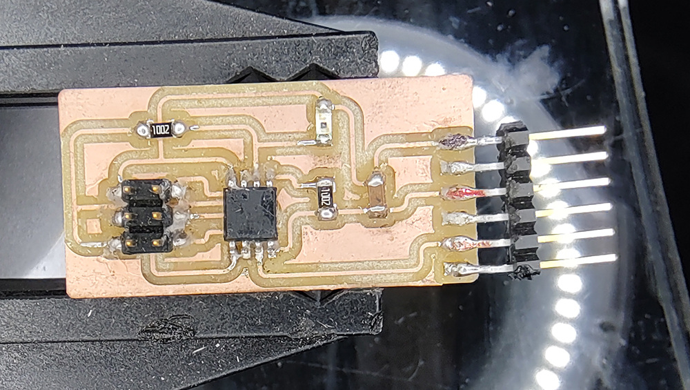
The phototransistor.
Fabrication process:
The fabrication process, both the milling at the Roland MDX 540 and the soldering was straightforward and uneventful. Everything worked on the first attempt (Unlike the process of the boards to control the servos!).
Programming:
I used the Arduino IDE to upload the codes provided, both the C code for the board itself and the Python code for the graphic interface which reports the light levels detected by the phototransistor.
The C Code was obtained at the Fab Academy web site
The Python Code for the board, used to get the visualization bar linked to the phototransistor is the following, in its original format as obtained from the Fab Academy web site:
#
# hello.light.45.py
#
# receive and display light level
# hello.light.45.py serial_port
#
# Neil Gershenfeld
# CBA MIT 10/24/09
#
# (c) Massachusetts Institute of Technology 2009
# Permission granted for experimental and personal use;
# license for commercial sale available from MIT
#

from tkinter import *
import serial

WINDOW = 600 # window size
eps = 0.5 # filter time constant
filter = 0.0 # filtered value

def idle(parent,canvas):
   global filter, eps
   #
   # idle routine
   #
   byte2 = 0
   byte3 = 0
   byte4 = 0
   ser.flush()
   while 1:
      #
      # find framing
      #
      byte1 = byte2
      byte2 = byte3
      byte3 = byte4
      byte4 = ord(ser.read())
      if ((byte1 == 1) & (byte2 == 2) & (byte3 == 3) & (byte4 == 4)):
         break
   low = ord(ser.read())
   high = ord(ser.read())
   value = 256*high + low
   filter = (1-eps)*filter + eps*value
   x = int(.2*WINDOW + (.9-.2)*WINDOW*filter/1024.0)
   canvas.itemconfigure("text",text="%.1f"%filter)
   canvas.coords('rect1',.2*WINDOW,.05*WINDOW,x,.2*WINDOW)
   canvas.coords('rect2',x,.05*WINDOW,.9*WINDOW,.2*WINDOW)
   canvas.update()
   parent.after_idle(idle,parent,canvas)

#
#  check command line arguments
#
if (len(sys.argv) != 2):
   print("command line: hello.light.45.py serial_port")
   sys.exit()
port = sys.argv[1]
#
# open serial port
#
ser = serial.Serial(port,9600)
ser.setDTR()
#
# set up GUI
#
root = Tk()
root.title('hello.light.45.py (q to exit)')
root.bind('q','exit')
canvas = Canvas(root, width=WINDOW, height=.25*WINDOW, background='white')
canvas.create_text(.1*WINDOW,.125*WINDOW,text=".33",font=("Helvetica", 24),tags="text",fill="#0000b0")
canvas.create_rectangle(.2*WINDOW,.05*WINDOW,.3*WINDOW,.2*WINDOW, tags='rect1', fill='#b00000')
canvas.create_rectangle(.3*WINDOW,.05*WINDOW,.9*WINDOW,.2*WINDOW, tags='rect2', fill='#0000b0')
canvas.pack()
#
# start idle loop
#
root.after(100,idle,root,canvas)
root.mainloop()
Initially, the program was not functioning properly, and thus, we did not get the readings on the horizontal bar. Looking for an anser in stack overflow we found the suggestion of adding two new lines to solve a traceback error. After applying this fix, we obtained a correct reading of the phototransistor.
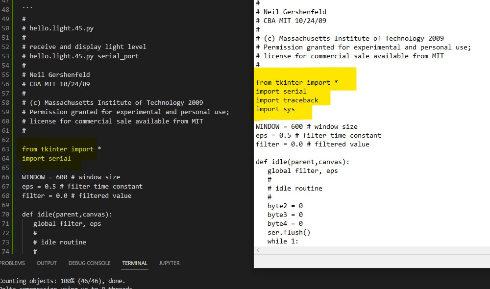
Please see the debugged version of the Python code, for use in Windows 10
#
# hello.light.45.py
#
# receive and display light level
# hello.light.45.py serial_port
#
# Neil Gershenfeld
# CBA MIT 10/24/09
#
# (c) Massachusetts Institute of Technology 2009
# Permission granted for experimental and personal use;
# license for commercial sale available from MIT
#

from tkinter import *
import serial
import traceback
import sys

WINDOW = 600 # window size
eps = 0.5 # filter time constant
filter = 0.0 # filtered value

def idle(parent,canvas):
   global filter, eps
   #
   # idle routine
   #
   byte2 = 0
   byte3 = 0
   byte4 = 0
   ser.flush()
   while 1:
      #
      # find framing
      #
      byte1 = byte2
      byte2 = byte3
      byte3 = byte4
      byte4 = ord(ser.read())
      if ((byte1 == 1) & (byte2 == 2) & (byte3 == 3) & (byte4 == 4)):
         break
   low = ord(ser.read())
   high = ord(ser.read())
   value = 256*high + low
   filter = (1-eps)*filter + eps*value
   x = int(.2*WINDOW + (.9-.2)*WINDOW*filter/1024.0)
   canvas.itemconfigure("text",text="%.1f"%filter)
   canvas.coords('rect1',.2*WINDOW,.05*WINDOW,x,.2*WINDOW)
   canvas.coords('rect2',x,.05*WINDOW,.9*WINDOW,.2*WINDOW)
   canvas.update()
   parent.after_idle(idle,parent,canvas)

#
#  check command line arguments
#
if (len(sys.argv) != 2):
   print("command line: hello.light.45.py serial_port")
   sys.exit()
port = sys.argv[1]
#
# open serial port
#
ser = serial.Serial(port,9600)
ser.setDTR()
#
# set up GUI
#
root = Tk()
root.title('hello.light.45.py (q to exit)')
root.bind('q','exit')
canvas = Canvas(root, width=WINDOW, height=.25*WINDOW, background='white')
canvas.create_text(.1*WINDOW,.125*WINDOW,text=".33",font=("Helvetica", 24),tags="text",fill="#0000b0")
canvas.create_rectangle(.2*WINDOW,.05*WINDOW,.3*WINDOW,.2*WINDOW, tags='rect1', fill='#b00000')
canvas.create_rectangle(.3*WINDOW,.05*WINDOW,.9*WINDOW,.2*WINDOW, tags='rect2', fill='#0000b0')
canvas.pack()
#
# start idle loop
#
root.after(100,idle,root,canvas)
root.mainloop()
Final Result:
I have a working light sensor, one of the key parts of my final project.
What I learned this week:
I could fabricate, program and obtain readings from a phototransistor. This will be one of the key PCBs for my final project, acting as the input device to provide information wich in turn will serve as parameters to open or close the blinds on the Shadowhouse. For the final project however, I will have to develop a new firmware, using serial communication.
Design, fabrication and programming Files here: