
This work is licensed under a Creative Commons Attribution-NonCommercial-ShareAlike 4.0 International License
Week 3: Computer-Controlled Cutting
Feb 16, 2021Summary
This week's assignments
- Group assignment:(**Please check our Group Assignment page**)
- Characterize your laser cutter's focus, power, speed, rate, kerf, joint clearance and types ✔
- Individual assignment:
- Cut something on the vinyl cutter and document how you made your vinyl cutting ✔
- Design, laser cut, and document a parametric construction kit, accounting for the laser cutter kerf, which can be assembled in multiple ways, and for extra credit include elements that aren't flat:
- Explain how you parametrically designed your files ✔
- Document how you made your press-fit kit ✔
- Include your original design files ✔
- Include your hero shots ✔
Resources Used
- Software: SOLIDWORKS, Adobe Illustrator
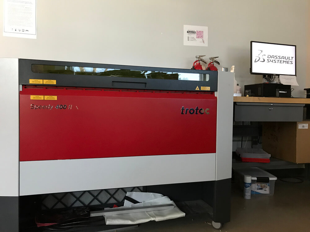
- Hardware: Trotec Speedy 400 Flexx (laser cutter), Roland DG CAMM-1 GS-24 desktop cutter (vinyl cutter)
Skills Gained
- Parametric design, Laser cutting, Vinyl cutting
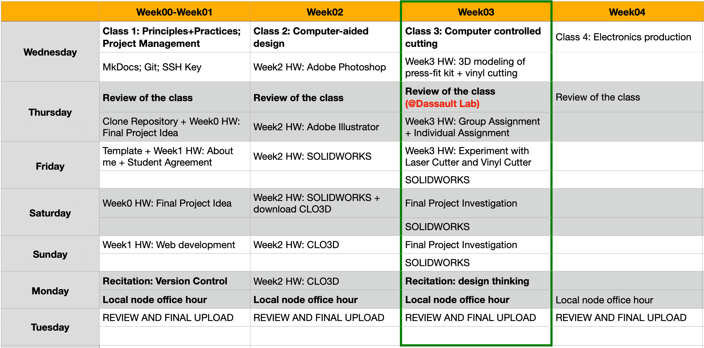
My Weekly Schedule
Training Session and Group Assignment
I have been looking forward to this week since I got accepted by the Fab Academy program. On Thursday, we received trainings from Greg and Alex on the vinyl cutting and laser cutting machines at Dassault Systèmes 3DEXPERIENCE Lab. Through the training, I have learned how to calibrate, use, and maintain the machines to extend their longevity. The most important lesson was safety, and I must keep this in mind all the time, not just for working with the vinyl cutter or laser cutter.
The group assignment this week was to characterize the focus, power, speed, rate, kerf, join clearance and types of the Trotec Speedy 400Flexx laser cutter in our lab. From this group assignment, I have learned how different combinations of speed, power, and frequencies can lead to different cutting and engraving performance. Please check our Group Assignment Page for more details.
Individual Assignment 1 - Vinyl Cutting
Chinese Knotting Design in Adobe Illustrator
After I found that the Lunar New Year (2021 is the Year of the Ox) was entering on Friday, I decided to create new year decorations as a way to celebrate this significant holiday in Chinese Culture.
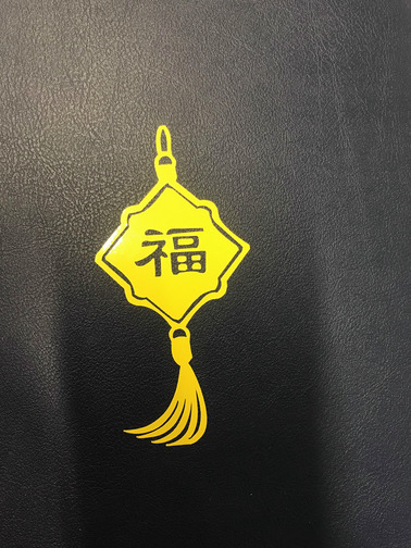
For the vinyl cutting assignment, I designed a Chinese Knotting with the Chinese character 福 [fú] in Adobe Illustrator.
The Chinese character 福 [fú] means "fortune" or "good luck". It is a common and widespread tradition for Chinese to display the Chinese character 福 [fú] on the wall in the living room, kitchen or on entrance of their home during the Spring Festival (春节 [chūn-jié]) each year.
The Chinese character 福 [fú] is often printed on a square piece of red paper and displayed upside-down. It is said that this is because the character for "upside-down", "倒" [dào], is a homonym of the character for "to arrive", "到" [dào]. So this means that "福" (happiness, good fortune, etc.) is "arriving".

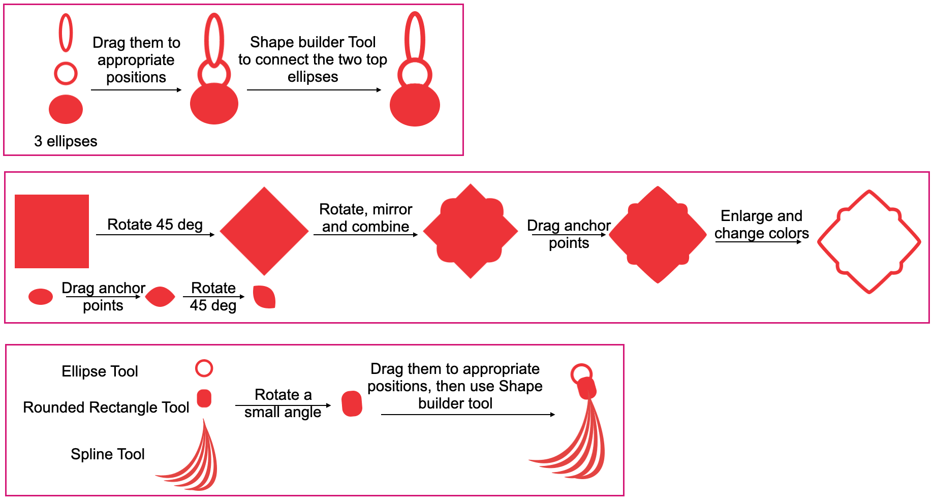
By combining common shapes with the simple Boolean operations, rotation and mirror, I was able to make the Chinese knotting. The font that I used for the Chinese character was the clerical script (隸書 / 隶书), which is a very old style of Chinese calligraphy.
After saving the file as a black-and-white bitmap image (.png), I was ready for vinyl cutting.
Vinyl Cutting
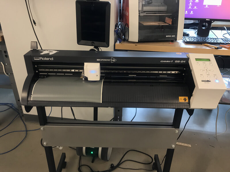
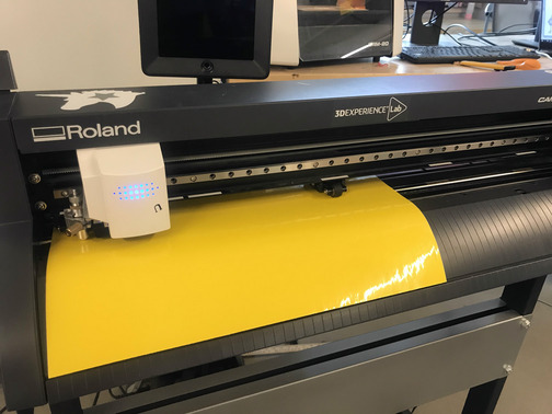
With the vinyl cutter, we can make crafts such as signs, labels and screen printing T-shirts, we can also make flexible circuits with copper vinyl. The vinyl cutter at the 3DEXPERIENCE Lab is a Roland DG CAMM-1 GS-24 cnc cutting machine, and the bundled software is Roland CutStudio.
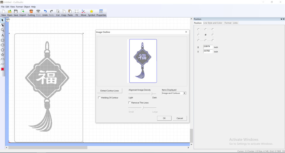
- I dragged my design (.png) to the Roland CutStudio software. The default start position is the bottom left corner of the canvas. I right clicked the image for contour detection. After the outlines were dected, I knew that the image was ready for vinyl cutting. As the CutStudio couldn't read an .svg file, I needed to use the .png file, which was not as accurate, as shown from the image outlines.
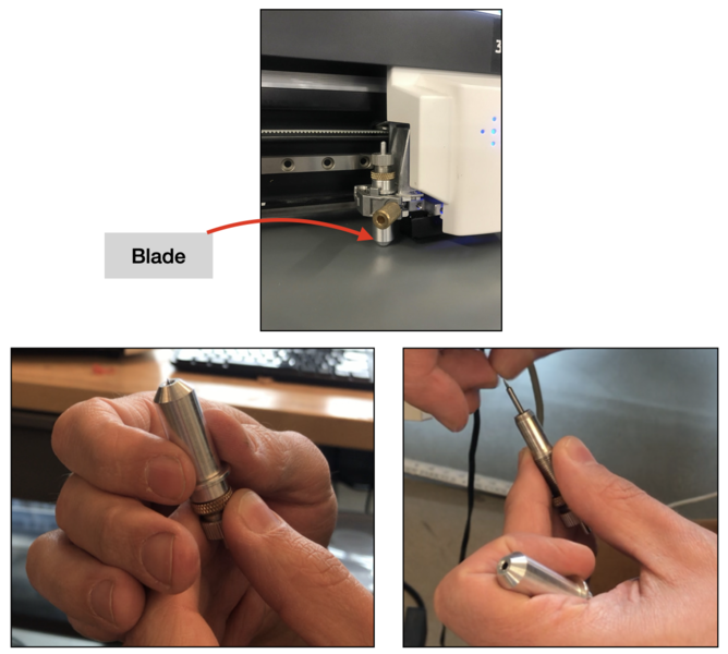
- The blade that we use for the machine is the Roland 45 degree blade (choosing the right blade). As the blade still looked new to me (Greg changed it on Thursday), I skipped this step and moved onto the next one.
- I lowered the loading lever (located on the back side of the machine) and inserted the vinyl film (I didn't notice that there was a roll of red vinyl sitting next to the sewing machine 😂). I pushed the vinyl film through the machine and pulled out on the front side of machine. Since the two edges of the vinyl film was not leveling, I used a box cutter to cut out the excess so that the bottom of the film aligned with the guideline (the straight groove). I also adjusted the pinch rollers and aligned with the appropriate white verification marks. Then I raised the loading lever to secure the material in place.
- After turning on the machine, I set the following settings on the vinyl cutter interface.
- Sheet mode: Roll
- Speed: 15 cm/s
- Force: 70gf 0.250 mm
- And I ran my first cut by printing the image from the CutStudio interface.
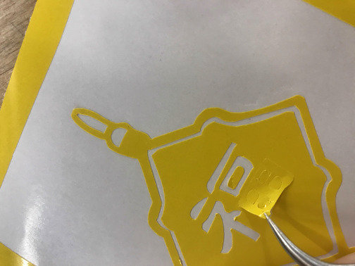
- I examined the cut, and I felt that I should have decreased the force a little since some delicate parts looked tearing up.I lowered the speed to 10 cm/s as well as the force to 60gf 0.250 mm. The result came out fine, so I proceeded to the next step, which was "weeding".
- To make sure not to damage the delicate parts, I used a tweezer to weed the excess vinyl. At first I was gently peeling the excess vinyl, but I found that I would have to "poke" the paper a little to get some delicate parts out, which was not effective, then after several trial-and-error, I figured that the result would be much cleaner when "shearing" instead of "peeling".
- At that moment, I was not access to the transfer tape, so I needed to apply my vinyl sticker to my laptop piece by piece. Although the final placement was not perfect, I enjoyed the blessing from my little sticker 😌!
I think vinyl cutting was very fun, and I learned a lot during the "weeding" process. There were delicate parts in my design and I think it was a good practice to me. This experience has given me more courage to experiment with copper vinyl as I would like to make flexible circuits for my project. I would also like to learn to use mods to operate the vinyl cutter - it seems so cool!
Individual Assignment 2 - Laser Cutting
Parametric Design in SOLIDWORKS
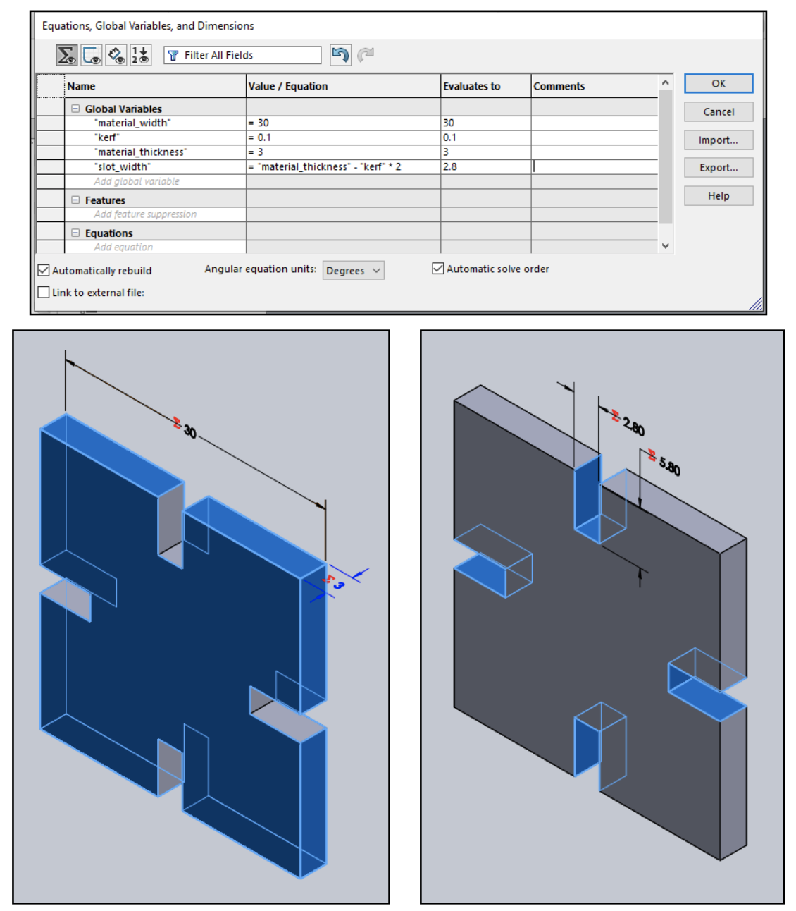
My first parametric press-fit construction kit was a six-piece identical small square piece with 30 mm x 30mm x 3 mm in measurement. It was a quick design, and the parameters that I used were: the square side, the slot width, the kerf, and the material thickness.
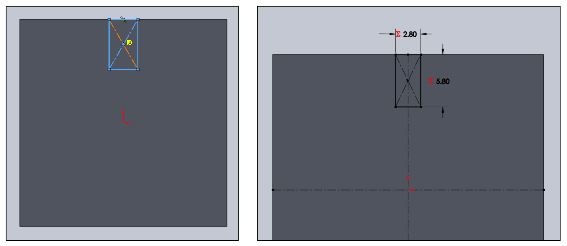
I used the 3 Point Center Rectangle tool when creating the slot because I wanted to take advantage of the center line and the drag function to set the constrains to the edge. Once I created my first slot, I used the Mirror tool to create the other three slots for my design.
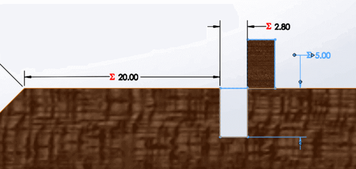
Laser cutting is a very precise process but there is still some material burned away by the laser, and that creates a differce. In order to create a press-fit construction kit, I need to make sure to account for the offset introduced by the laser when calculating the slot width. From the group assignment, I figured that the best-fit for the 3 mm plywood would be when the slot was equal to 2.8 mm, and since:
kerf = material_thickness - slot_width
The kerf for the 3 mm plywood would be 0.2 mm. However, when we are designing in CAD software, I should be dividing this number by 2 and use 0.1 mm for my calculation.
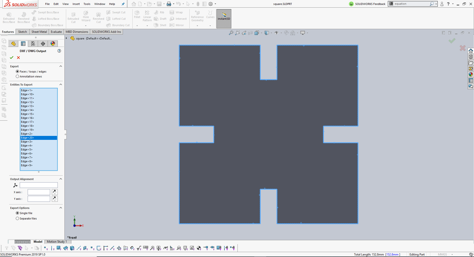
Once the part model was ready, I followed a similar process that I took in my previous assignment to export the file to .dxf format so that I could post-process the file in Adobe Illustrator for laser cutting. This time, I exported the edges instead of the front face, I was told that this could result in a more crisp look in Adobe Illustrator.
Laser Cutting and Kit Assembling
These is the machine, material and settings that I used for this assigment:
- Model: Trotec Speedy 400 Flexx
- Software: Adobe Illustrator + JobControl
- Work area: 40 x 24 inch
- Setting: Laser power - CO2
- Material: 3 mm plywood
- Engraving (Power/Speed/Frequency): 55/30/1000
- Cutting (Power/Speed/Frequency): 90/0.7/500
- After importing the .dxf to Adobe Illustrator, I made sure to adjust the thickness of the cutline to be 0.001 inch and set the color to true red (R/G/B = 255/0/0).
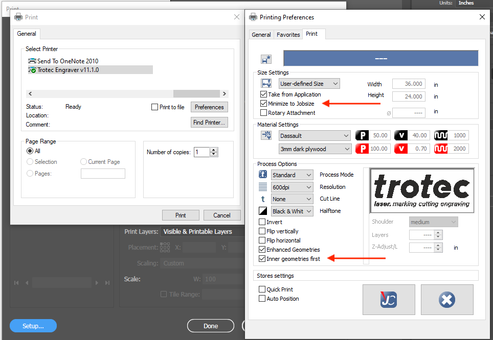
- Then, I pressed Ctrl + P on the keyboard, and I was greeted with the print preview window. Here, I made sure the following were checked in the setup preference window:
- Minimize to jobsize
- Inner Geometries first (which means the machine will perform the engraving first)
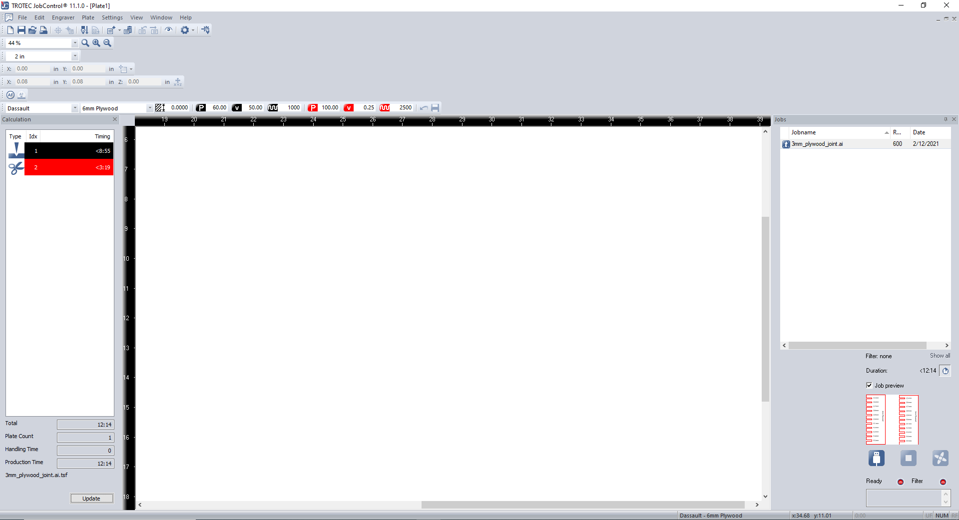
- After clicking the "Print" button on this window, Adobe Illustrator would connect to JobControl, which is the software that speaks to the Trotec laser cutter.
- Then, I powered on the trotec machine and connected it to the software by clicking the "Ready" button on the bottom right corner of the JobControl Interface. li>
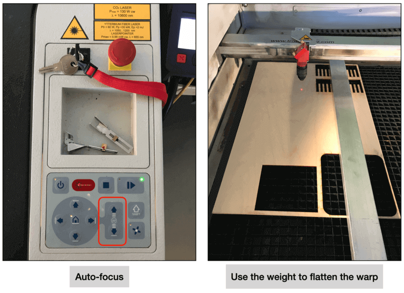
- I double clicked my file on the right panel and it showed up on the canvas. Next we would need to set the focus. The machine has a auto-focus function. Since the plywood that I was going to use was warping, I used a weight to flatten the warp and did the auto-focus a second time. I also used the four arrows (next to the auto-focus function) on the control panel to ensure the weight was not in the way of the job.
- Then, I set the material as 3 mm plywood and applied the following setting that I decided on from the group assignment.
- Engraving: (Power/Velocity/Frequency) = 55/30/1000
- Cutting: (Power/Velocity/Frequency) = 90/0.7/500
- Here is a video of the laser cutting in action. I found it mesmerizing to watch the laser do its job, however watching this for too long can hurt the eyes. Yet...
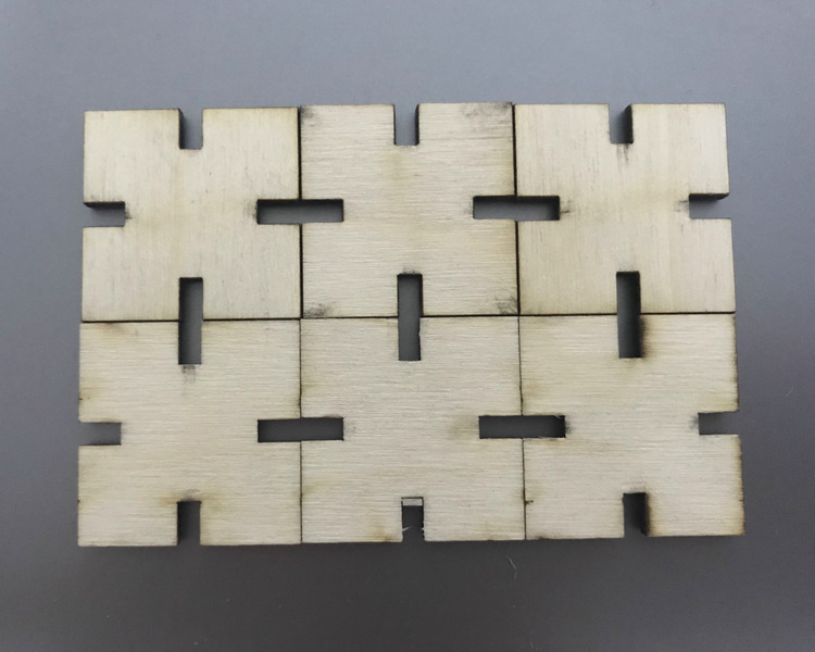
- Here is a picture of the six pieces for my first kit:
- Finally, playing around with assembling the parts in multiple ways...
**Note: engraving is true black (R/G/B = 0/0/0)
Alex also reminded us not to start the job at the origin (top left corner), and that means the job should start at least at (X,Y) = (0.1, 0.1).
Never turn your back on the laser 😎!!
Experimenting with the Joint
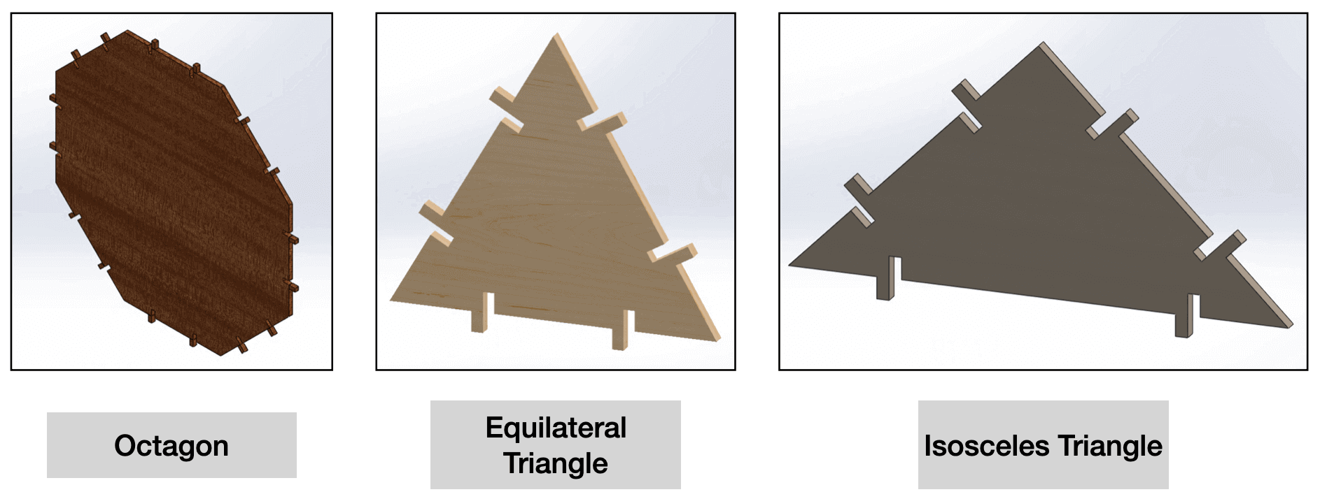
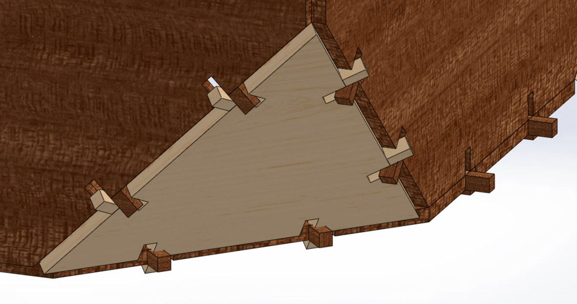
Over the weekend, I designeed another kit in SOLIDWORKS, which consisted of various number of octagonal, equilateral triangular, and isosceles triangular pieces.
I wanted to cut the pieces out of 3 mm plywood, and the group assignment has helped me understand what kerf size I wanted to apply.

I designed the same positive and negative slots sitting next to each other because I wanted to see if the shapes can still result in a snug fit without an extra joint piece.
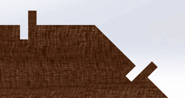
At this moment, I was using a slot length that was slightly longer than the thickness of the material. I was not sure which value would provide the best fit and I would need to test it with the laser cutting machine.
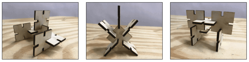
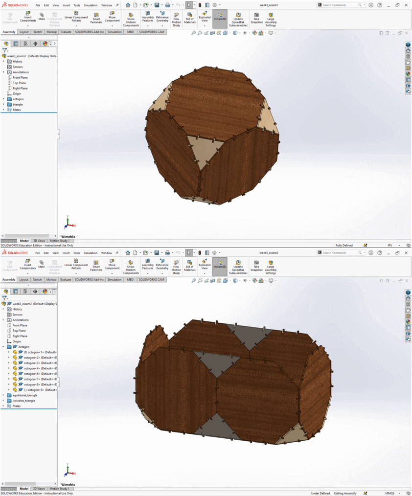
As I was not access to the lab during the weekend, I decided to test the kit in SOLIDWORKS. The assembly model has shown that there would be a small portion of the joint extruding when placing the pieces in perpendicular position (Image 2 - Assembly 2), and I had expected that because I set the slot length to be slightly longer than the material thickness so that the pieces can be when joined at an angle to create a dodecahedron (Image 2 - Assembly 1).
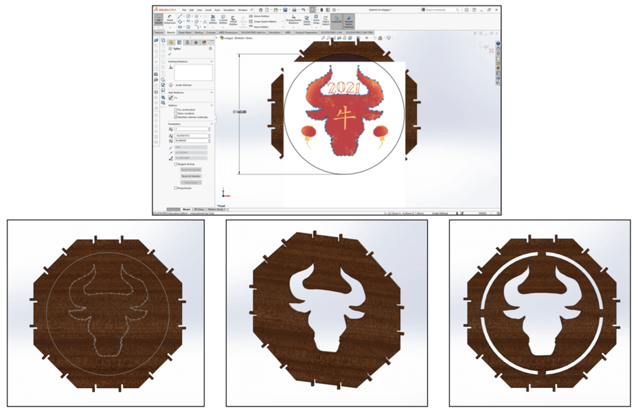
To add some fun, I used the Sketch Picture tool in SOLIDWORKS and played with it by tracing the ox with the Splines tool, extruded cut to visualize how it would look for laser cut.
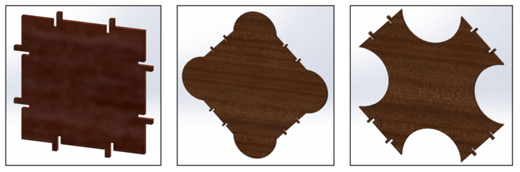
Finally, I added a square piece to the kit, and manipulated the octagonal piece to have two more shapes (i.e. adding or subtracing a half circle for 4 sides).
Currently I set the dimension for a side as 80 mm so that the joint would be relatively small for a more visually appealing look. However, this might not be feasible as I could be cutting many pieces to form a kit that can be assembled in multiple ways. To this point, I would still need to experiment with the dimensions before proceeding to the laser cutting step. Always "measure twice, cut once" 😄!
Files
Please find below the files that I made for this assignment.
- Group Assignment - Joint Clearance Design Files
- Vinyl Cutting - Chinese Knotting with "Fu"
- First Parametric Press-fit Construction Kit
- Second Parametric Press-fit Construction Kit