
This work is licensed under a Creative Commons Attribution-NonCommercial-ShareAlike 4.0 International License
Final Prototype and Presentation
Summary
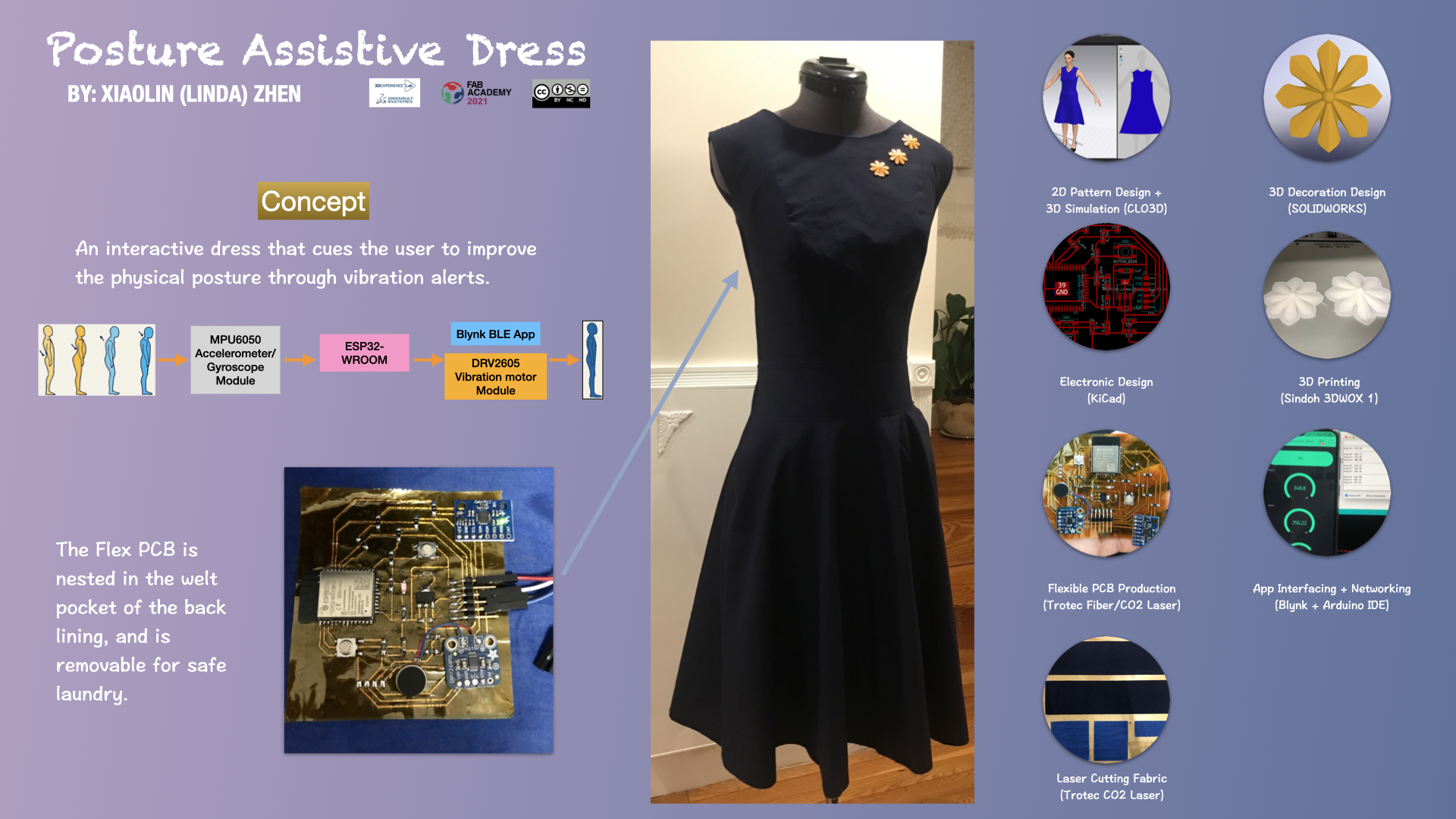
Giada (the final project's name) is an interactive dress that responds to the poor posture of the user and cues her through vibration alerts, and the inspiration behind this project was the aesthetic and medical purposes of corsets.
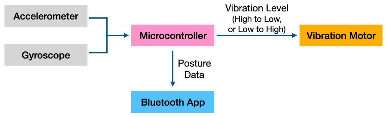
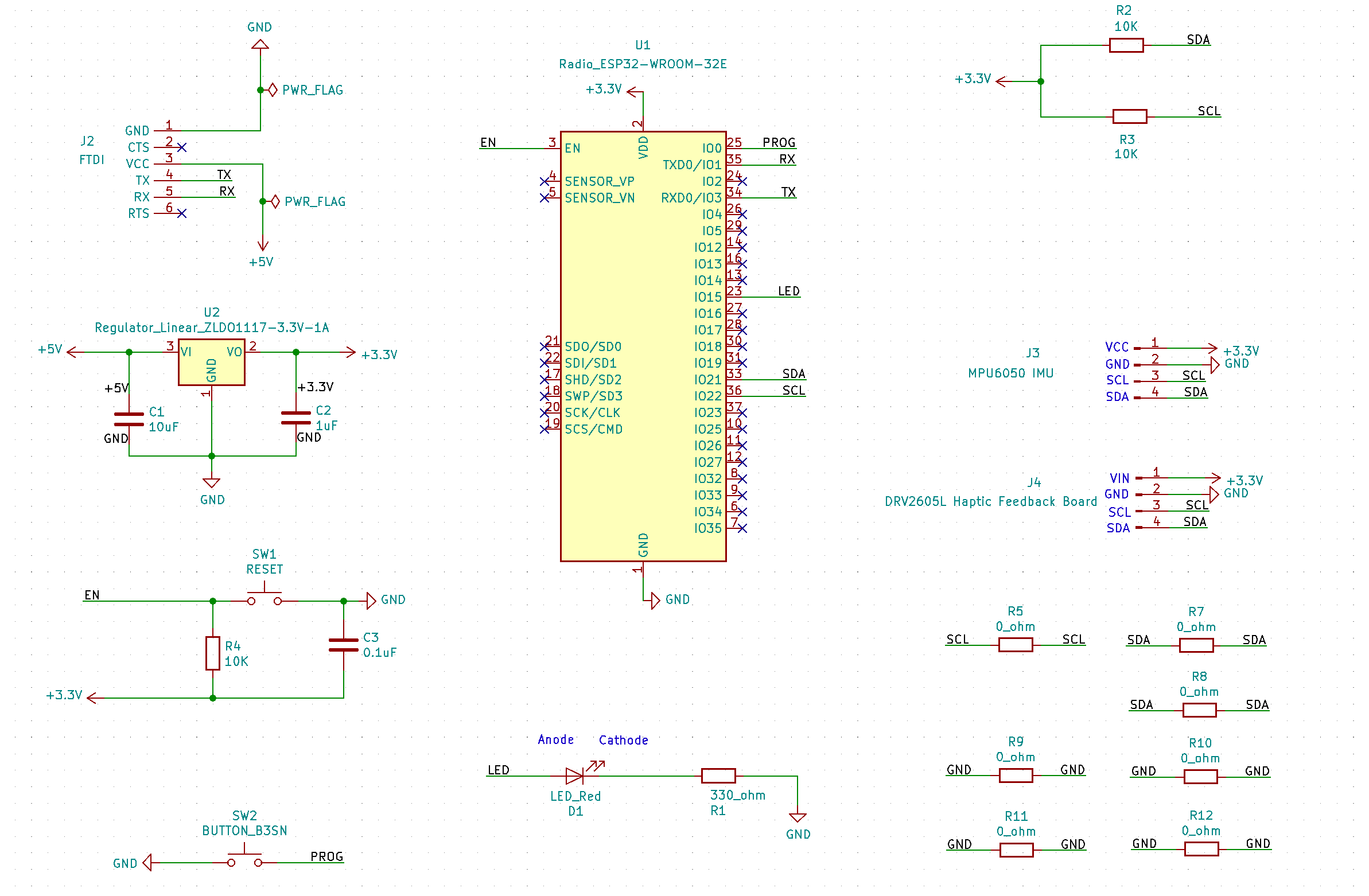
One of the key creative accomplishments was the flexible PCB. Controlled by ESP32-WROOM, the flexible PCB has the MPU6050 accelerometer/gyroscope as the input device and the Adafruit DRV2605 vibration motor module as the output device. Both modules utilize I2C for communication.
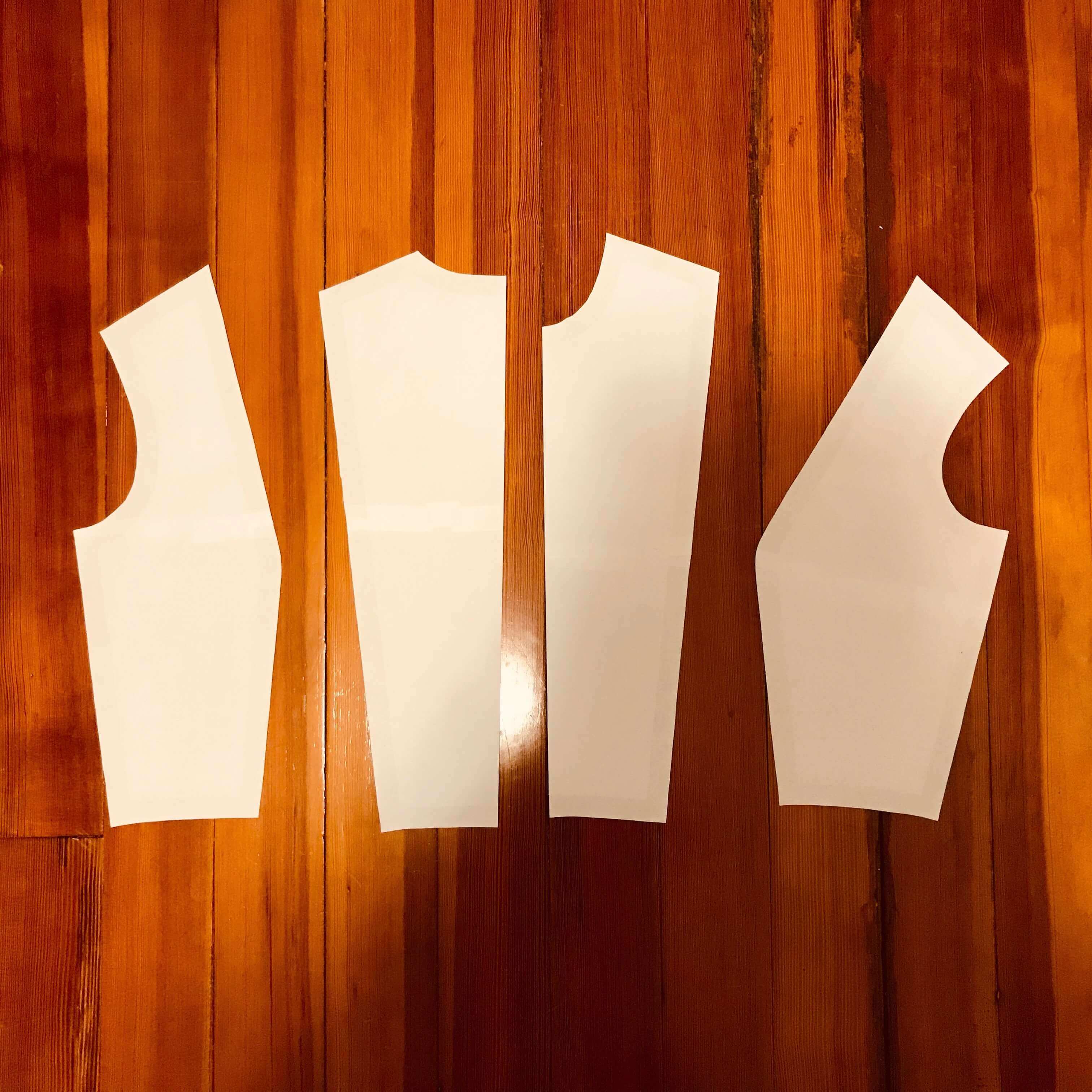
The first version of the dress was designed using CLO3D fashion design software and the later versions of the dress was modified in paper patterns. I learned that a dress with a fitted bodice is important as this allows the flexible PCB to "attach" to the back of the user as much as possible, which in turn to provide more accurate results.
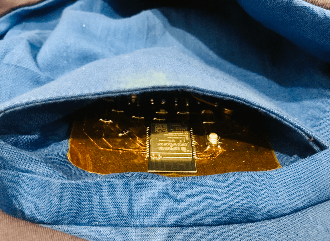
For systems integration: initially I was thinking of sandwiching the flexible PCB in the main fabric and lining of the dress. Later, as I discovered that I wanted to iterate the PCB design post-fabacademy, I decided not to sew the flexible PCB into the lining. In this new approach, I chose to create a "welt pocket" inside the back lining to serve as the nesting place for the flexible PCB. As the flexible PCB has a taped back, it is easily removable for safe laundry.
Below you could find the final project summary slide and the accompanied video featuring the processes and the functional testing of the dress.
Jul 5, 2021
Update: Please find below a short video for the flex PCB testing, which was performed about 3 weeks after the flex PCB production (Jun 07, 2021). Part 1 is for testing the networking between the input device (accelerometer/gyroscope module) and output device (vibration motor) and Part 2 is for testing the Blynk App. While testing, I noticed that besides being more delicate than an FR1 PCB, the flex PCB was not as sensistive as its first test (Jun 10, 2021). As a result, there was time lag in getting the readings from the Blynk app. When debugging, I noticed that the recurring error that I received from my flexible PCB was as follows, Failed to connect to ESP32: Timed out waiting for packet header, which was the same error that I received in Activity Log 2. However, I have made sure the continuity was all right, so I assumed it was some other problems. From this online tutorial, I learned that I could connect a 10 uF electrolytic capacitor between the EN pin and GND.
Analysis
1. What does it do?
The project is about an interactive dress that responds to the poor posture of the user and cues her through vibration alerts.
2. Who has done what beforehand?
My project was inspired by Wearable X's smart yoga pants which help monitor the right posture of the user during yoga practice.
Here are some prior arts by Fab Academy students:
- Victoria Peredo Robinson: Posturea
- Kiyeon Lee: Posture Nudger
- Carlos Nina Ochoa: Robotic Spiral Brace
3. What did you design?
The designs that were included in this project are:
- Dress sewing pattern (2D design and 3D simulation in CLO3D)
- ESP32 PCB design (KiCad)
- Decoration design for the dress (SOLIDWORKS)
- App design (Blynk and Arduino IDE)
4 - 6. What tasks have been completed, and what tasks remain? What has worked? What hasn't? What questions need to be resolved?
During the Applications and Implications week, I described the following evaluation criteria for my project:
- Does the dress have laser cut and/or 3D printed decorations?
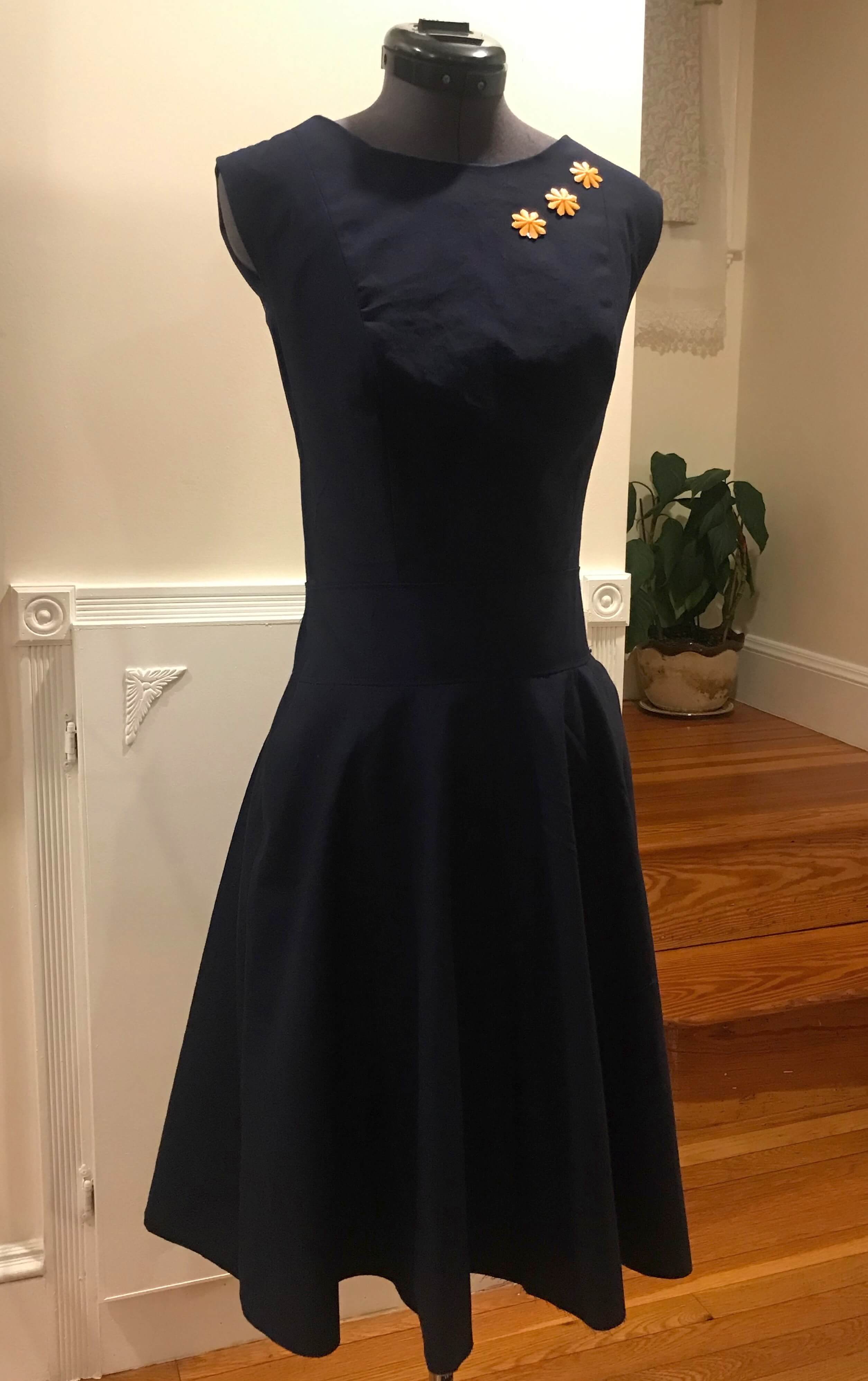
- Result: The dress incorporates 3D printed brooch on the bodice. However, due to most of the pattern sizes exceed the laser cutting machine work area, the dress does not have the laser cut decorations that I planned before. In the future, one workaround could be to laser cut the decoration patterns after manual cutting the sewing pattern pieces on the fabric; another workaround could be to make smaller sewing pattern pieces and include extra seam allowance as needed.
- Does the vibration motor buzz at a certain angle? (use phenolic paper or some thinner boards for testing)
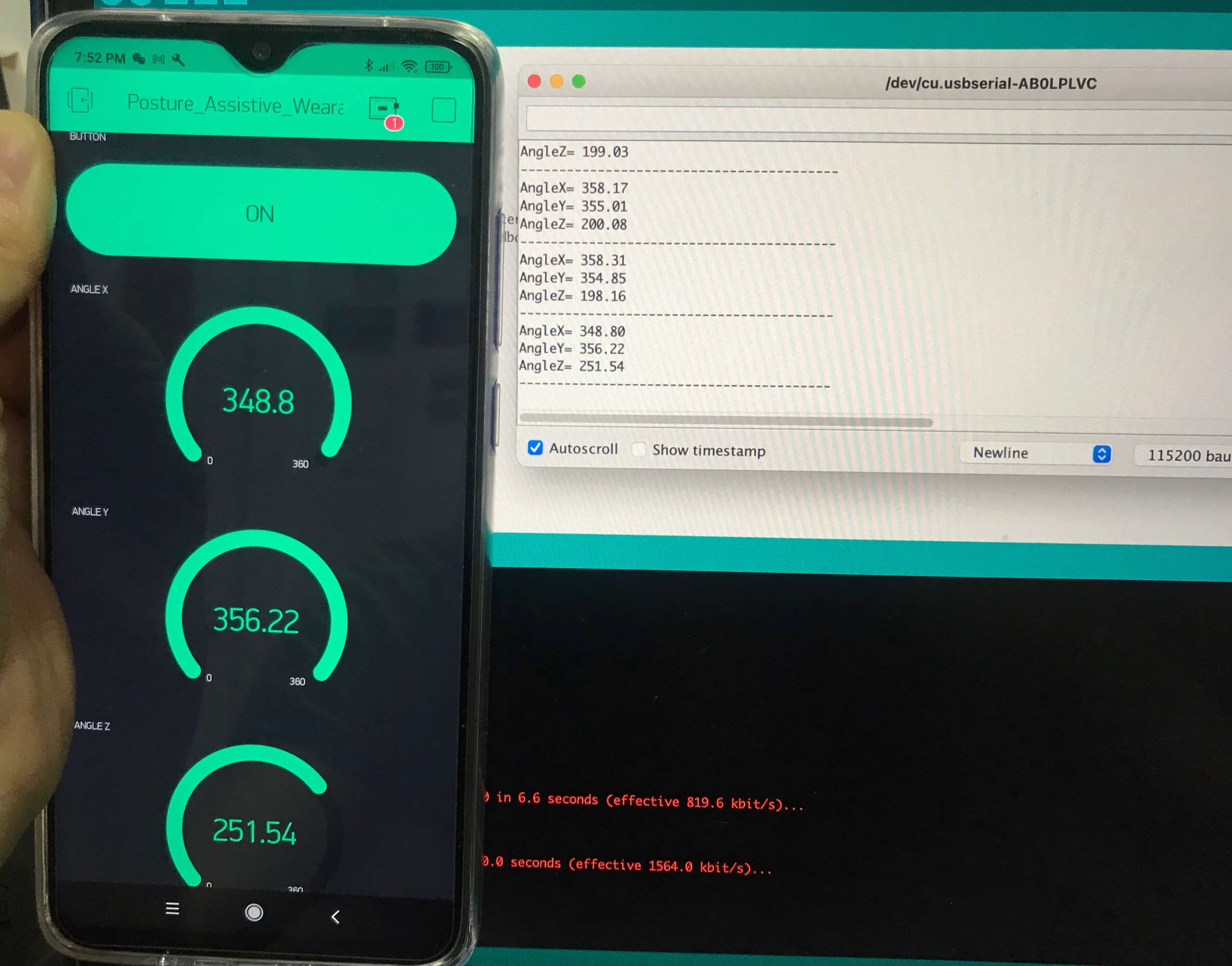
- Result: The vibration motor is able to buzz when X, Y, Z reaches a certain threadshold, as a result, a warning message from the serial monitor of Arduino IDE appears.
- Does the app work?
- Result: The Blynk WiFi/BLE app is able to read real-time gyroscope data (degree angles); the app is able to turn on or off the power indication LED of the flexible PCB. However the app has not been able to warn the user for bad posture yet, and this is an area for improvement in the future.
- Are the electronic components packaged inside the dress well?
- Result: The electronics are sealed nicely with the help of the "welt pocket". Currently, the system is powered by the FTDI programmer and it is connected to the laptop / Arduino IDE. As a matter of fact, the system is dependent on the jumper wire connections. Another drawback for the current system is that, FTDI pins on the flexible PCB are prone to damage, as a result, I must be careful not to stretch the PCB too hard. Now that I have learned about the microcontroller and PCB design, my next spiral would be to create a battery-powered PCB.
7. What will happen when?
Please refer to the Fabrication Processes section for more details.
8. What have you learned?
Overall, I was very proud of my accomplishments. This has been one of the most challenging projects I have worked on so far and I was really happy that my efforts got paid off. Throughout the project, I have strengthened my CAD skills, I have learned how to design for the 3D printer and the laser cutter.
Prior to the Fab Academy course, I knew little about circuit design and application development, however, thanks to this course, I have mastered my soldering skills and flexible PCB production skills.
This experience has sparked my interests in digital fabrication, I look forward to including different skills I acquired from this course to my future projects.
9. What is the dissemination plan and licensing of your final project?
During the Invention, Intellectual Property, and Income week, I proposed to use this dress as a workshop kit to teach children (especially young girls) about sewing, digital fabrication and programming. My instructor has confirmed that it would make a great kit to teach soldering and programming. Moving forward, I think it is ideal to replace the FTDI with the battery supply prior to making this a workshop kit. Another upgrade of the board could be to embed an RF sensor on the back of the flower brooch, to provide the user an option of turning off the buzz that came from the vibration motor.
The licensing of haptic feedback dress will be under Attribution-NonCommercial-ShareAlike 4.0 International (CC BY-NC-SA 4.0).
Fabrication Processes
2D Design and 3D Simulation: Dress Pattern
During the Computer-Aided Design week and the Wildcard Week, I experimented with a fashion design software called CLO3D. This is a power tool that allows pattern creation using either standard sizing tables or an individual's set of measurements. Another nice feature about this tool is their virtual-true-to-life garment visualization engine that allows the user to test the fit of the patterns and experiment with different cloth materials before making the first cut.
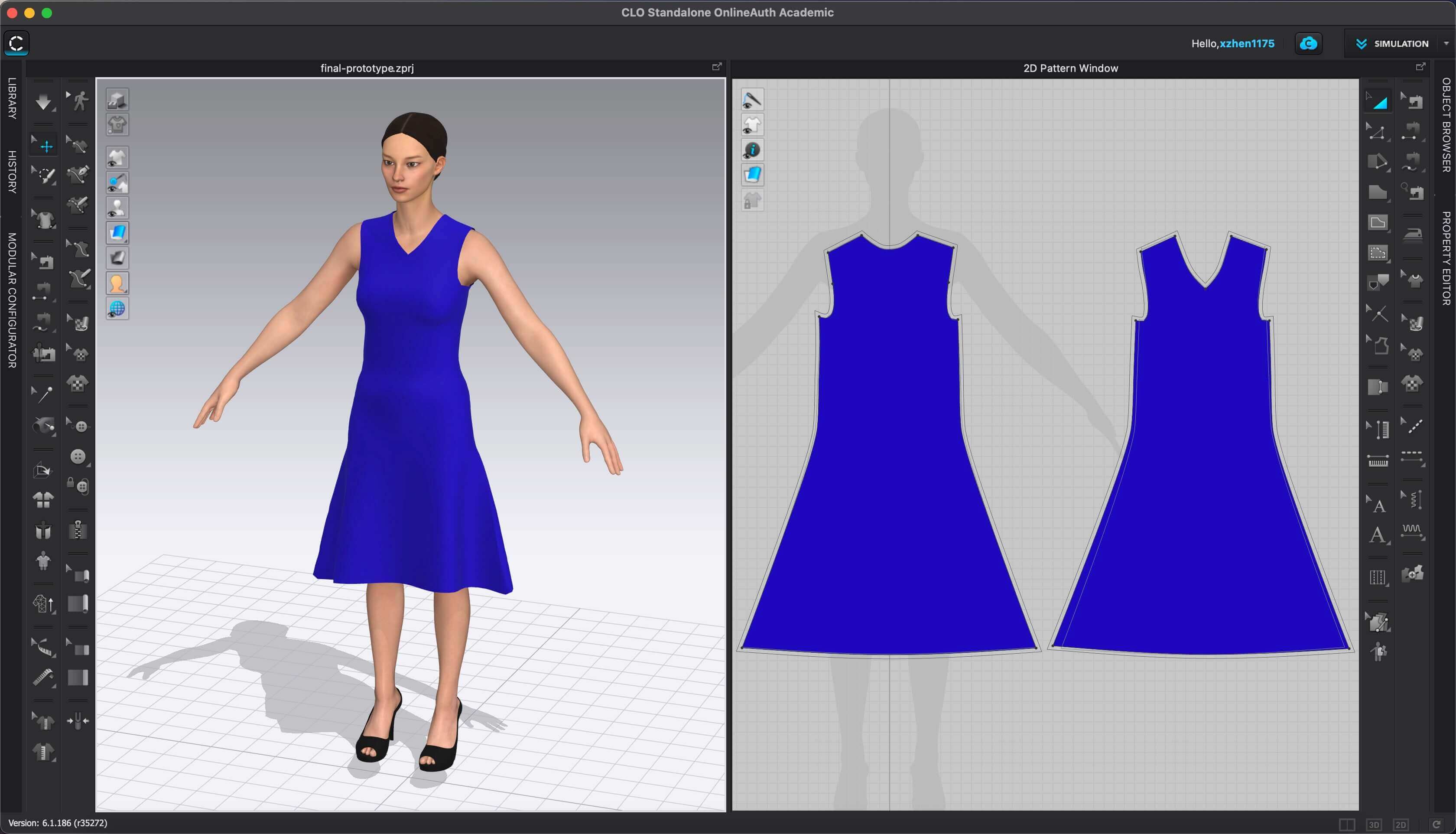
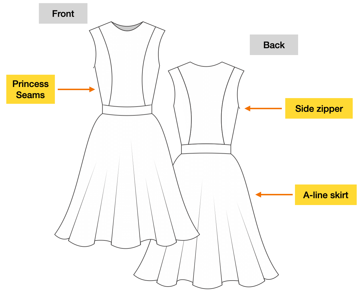
From here, I have the dress bodice for my size. Next, I modified the bodice pattern pieces to include the princess seams. As mentioned above, a fitted bodice is important to the accuracy of the data captured. The princess seam adds style to the top, while maintaining a smooth, body-skimming fit. I was still a little concerned about the thickness because the ESP32-WROOM was quite big as a microcontroller (0.5 mm). To make the dress as comfortable to wear as possible, I included the "tolerance" (0.5mm ease) in my sewing pattern, so this dress is slightly loose if I remove the PCB. I have included a more detailed activity blog (Activity log 1) for the pattern design and sewing process.
3D Design and 3D Printing: Brooch
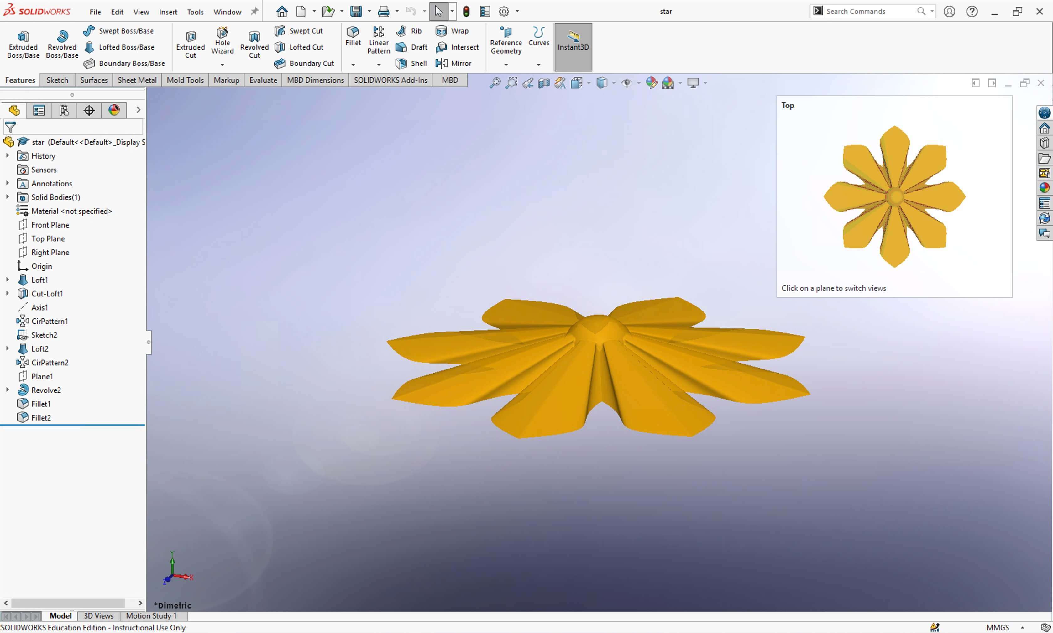
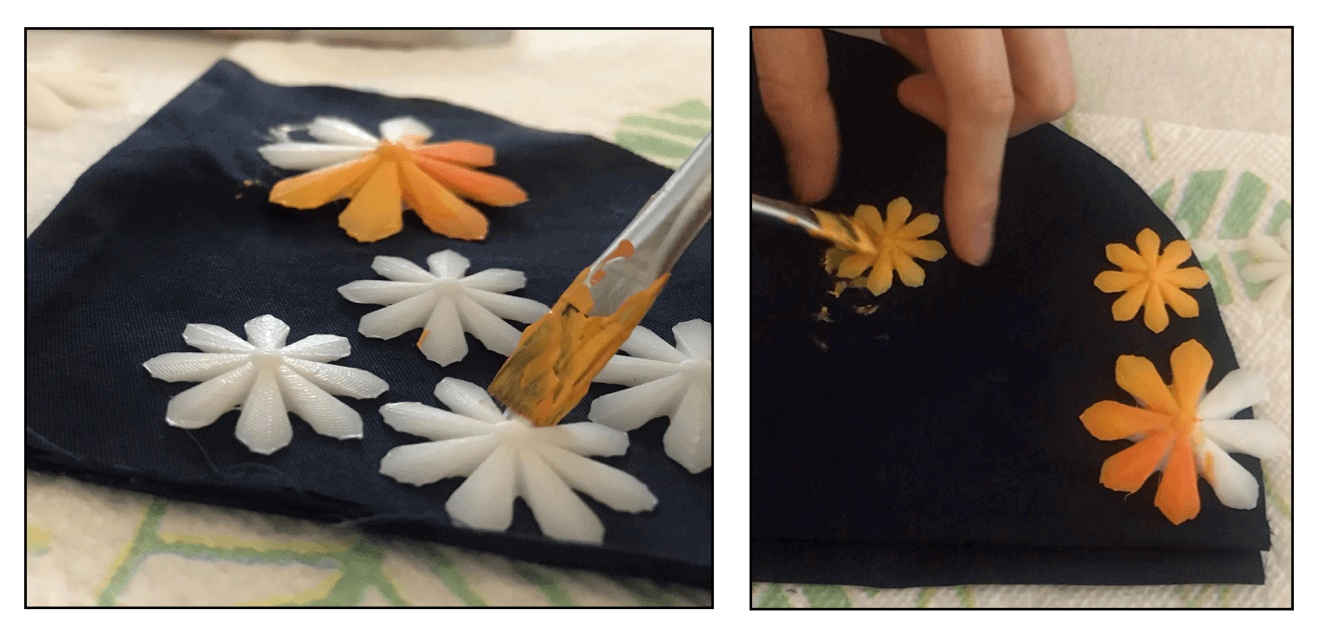
During the 3D Scanning and Printing week, I learned how to work with the different 3D printers in our lab. While I have decided to apply 3D printing techniques in my project during this week, the actual design and manufacturing process were accomplished later. In my project, I chose to apply 3D printing on the decoration. First, utilizing the Loft and Circular Pattern features, I designed a flower brooch in SOLIDWORKS.
Then, I used the Sindoh DWOX DP201 3D printer to print the brooch because this printer print quite efficiently with adequately good precision. I realized that my design was a little large to the dress, so I reduced the flower size to 60% of its original size when printing.
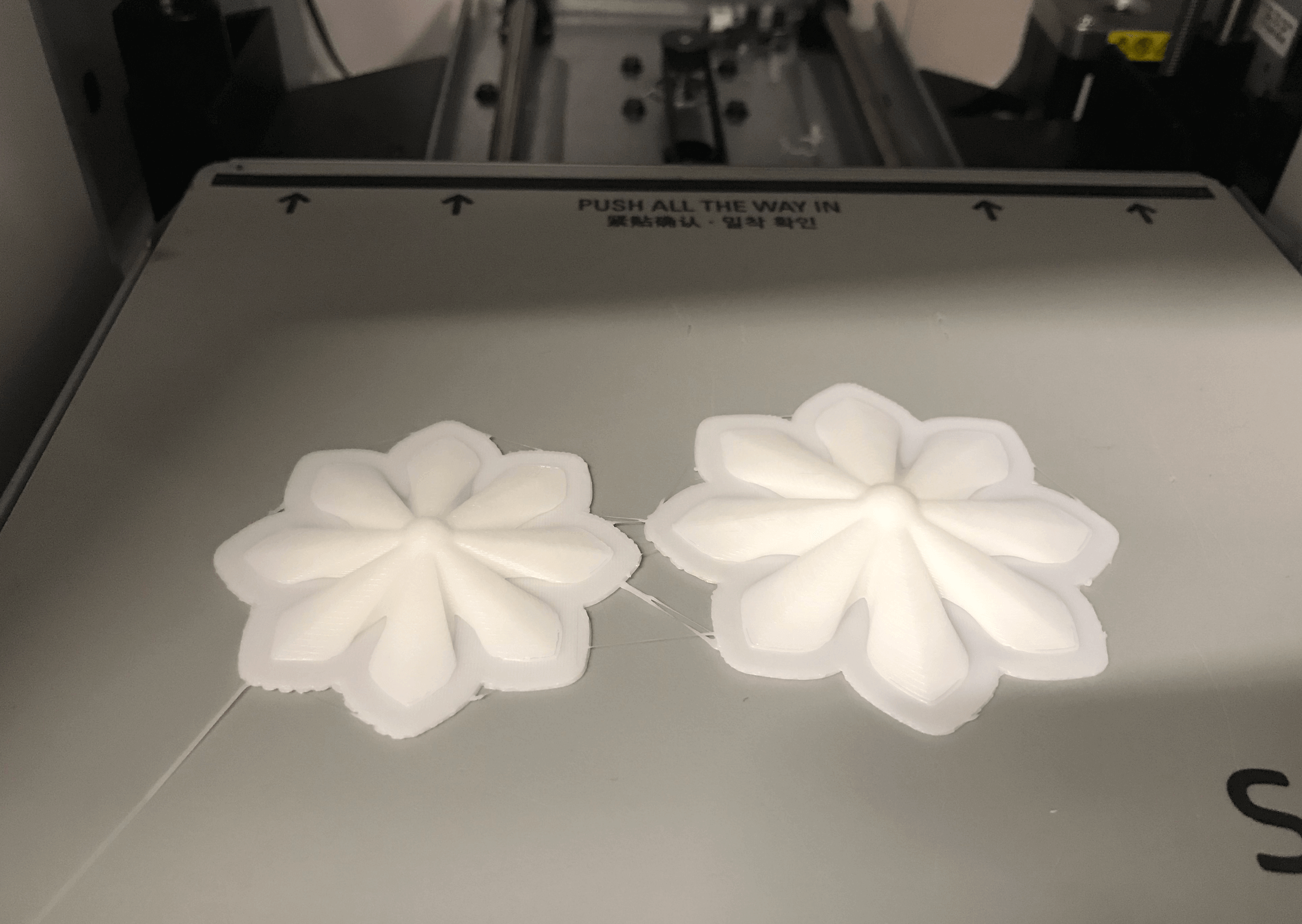
I preferred the flowers have colors other than white, so I painted them using a golden acrylic paint. Lastly, I set aside three flowers that I thought most beautiful as the brooch of the dress. I have included a more detailed activity blog (Activity log 3) for 3D design and printing the decoration.
Electronic Design and Production
During the Networking and Communications week, I took the challenge to upgrade my TinyAVR 1-Series board with the ESP32-WROOM-32 microcontroller. The main reason for that was because this microcontroller has the bluetooth feature, which would help with the bluetooth application development of my project.
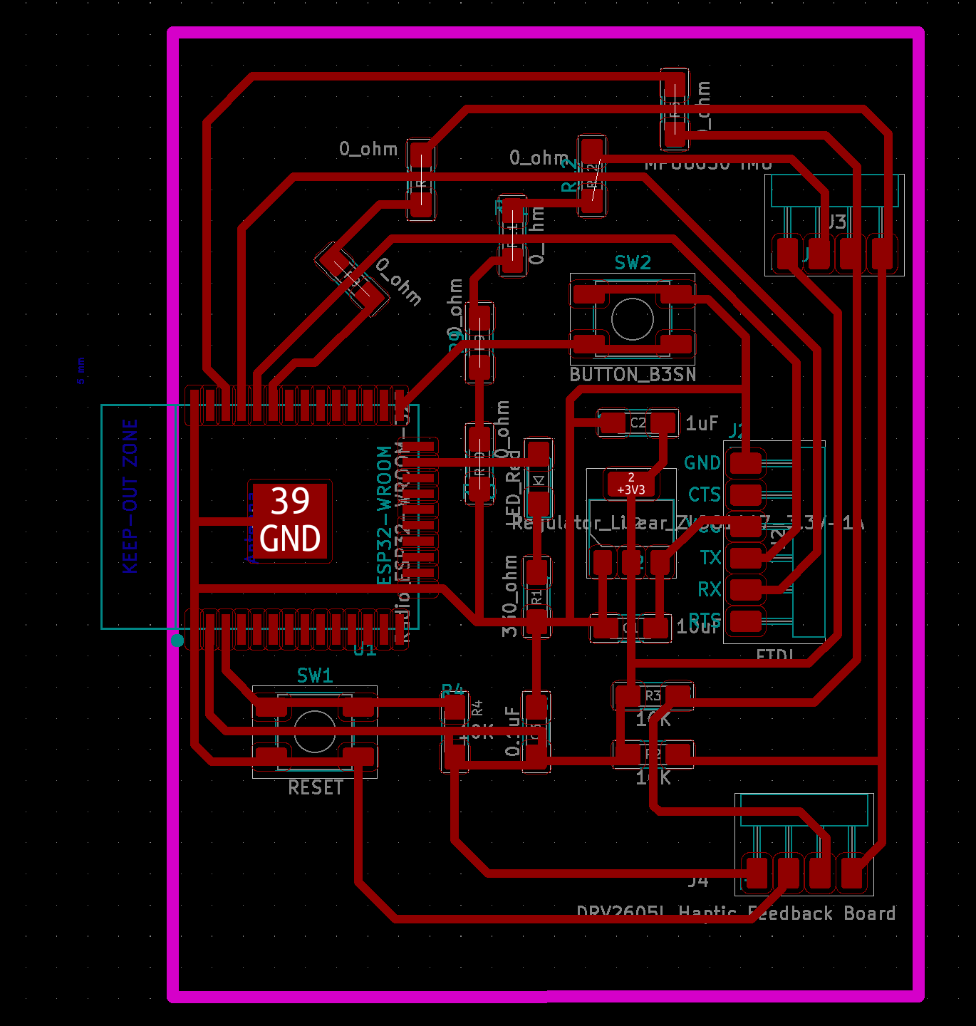
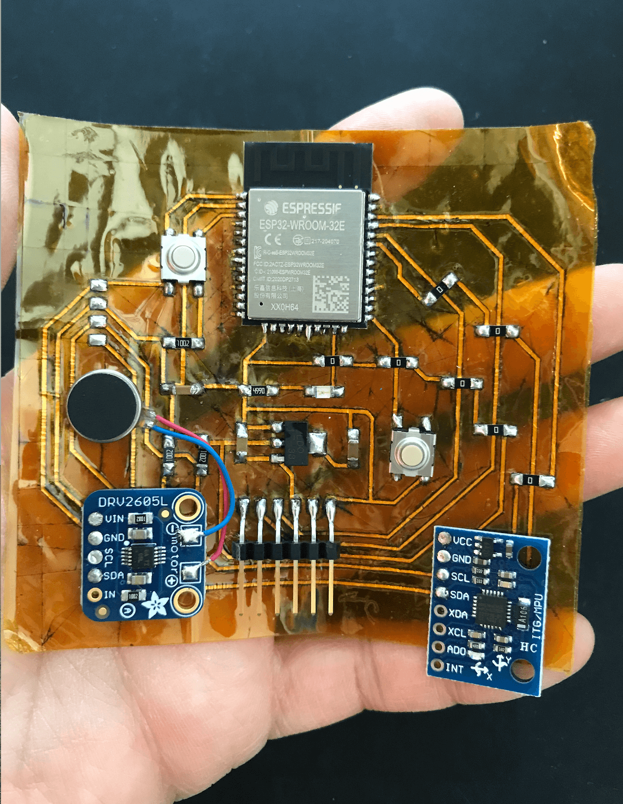
As I learned that it was challenging to produce a flexible PCB using copper vinyl, I chose to work in spirals when building my board. I started with a commerical breakout board to understand how ESP32-WROOM works, then I developed upon Neil's board on my PCB and produced it on a FR1 board. I then tested the I/O devices on my FR1 board, once I made sure the design work, I moved onto optimizing the PCB design and fiber laser settings for flex PCB production. For future reference, the fiber laser settings for this board would be: P: 55; V: 0.6; Frequency: 2000; Pass: 1. The most challenging part was weeding the excess copper traces. However, with patience and practice, I was finally able to produce a programmable flexible PCB in time, and this is how it looks. I have included a more detailed activity blog (Activity log 2) for flexible PCB production.
App Interface and Networking
After screening different tools (Bluetooth Serial, MIT App Inventor and Blynk), I chose to use Blynk and Arduino IDE to develop the bluetooth application (BLE) for my system. I find the Blynk user interface easy to work with and that the BLE feature of the app works for iOS and Android phones. When developing the Arduino sketches, I referred to Adafruit's libraries for MPU6050 and DRV2605 modules. I started with WiFi, then added BLE in the sketch. Below you can find a snippet of the code that I used for the application.
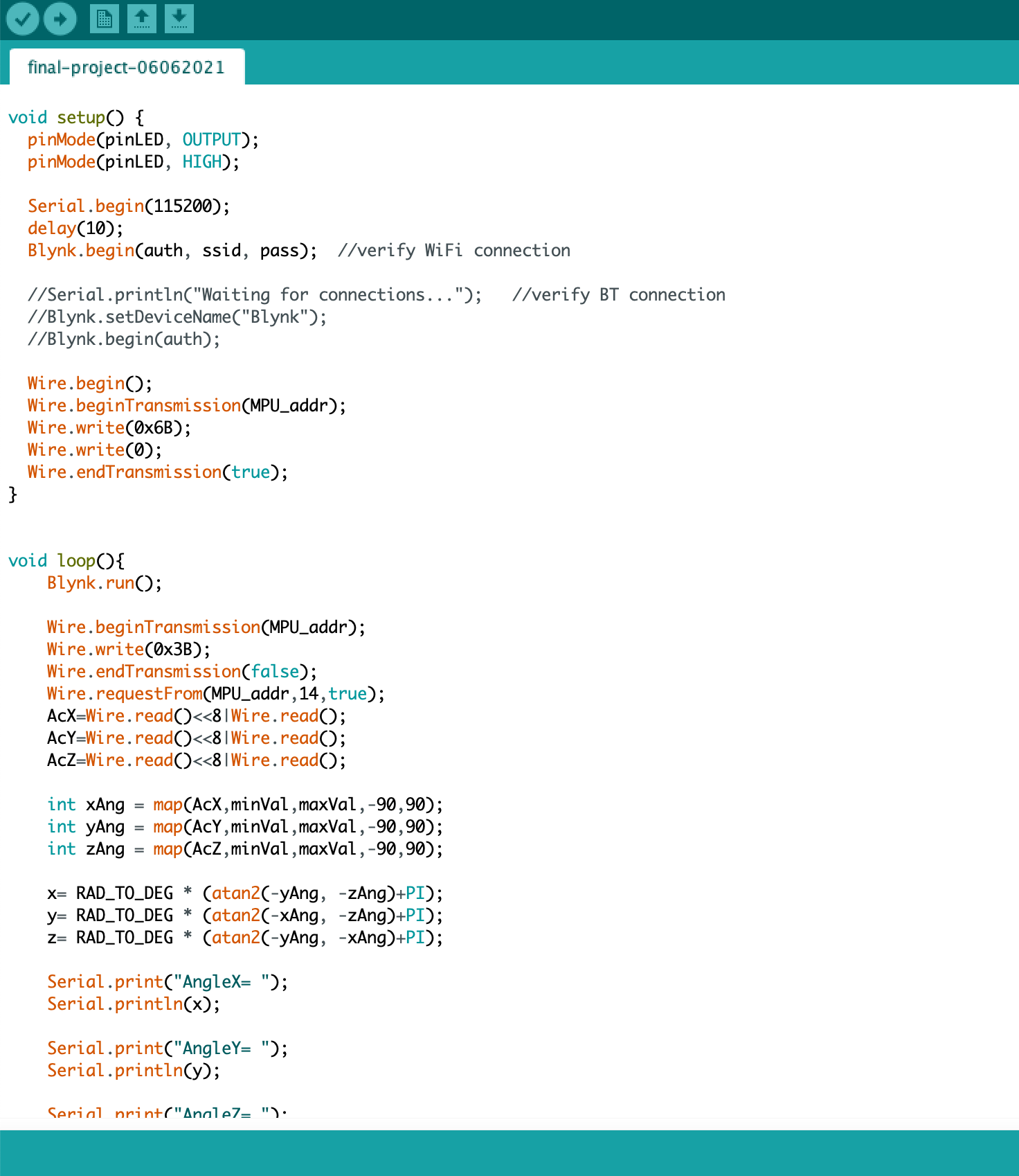
Currently, the app is able to read the real-time gyroscope data and turn on/off the LED. I have included a more detailed activity blog (Activity log 4) for the Bluetooth Application development of the project.
Laser Cutting, Sewing and System Integration
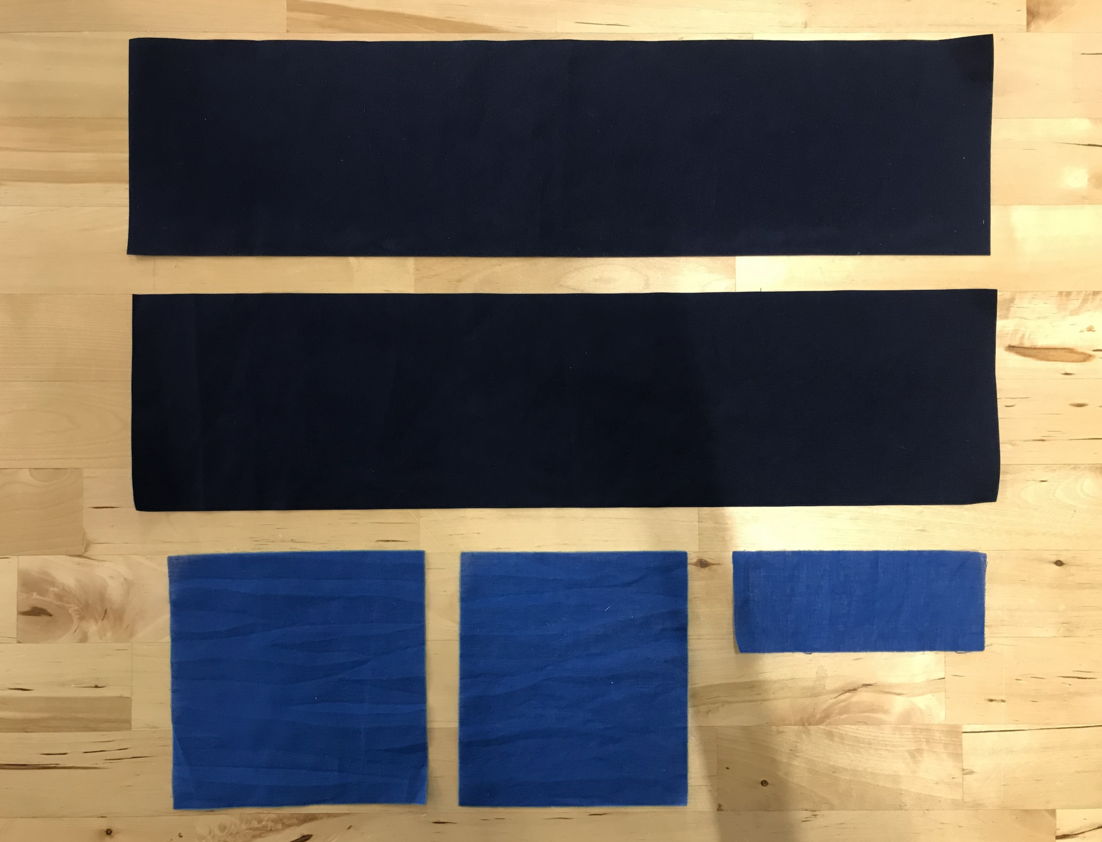
During the Output Devices week, I received training on textile laser cutting. The fabric that I chose for my project is a ligh-to-medium-weighted linen fabric (fabric weight: 190 GSM, color: navy blue). Although I was not able to laser cut most of my sewing pattern pieces because they were too large for the machine work area, I was still able to laser cut the smaller pieces (i.e. welt pocket and the waistband).
For the final prototype, I opted for a side zipper as I had planned to nest the flexible PCB on the center back of the dress bodice. Regarding system integration: initially I was thinking of sandwiching the flexible PCB in the main fabric and lining of the dress. Since I wanted to improve the PCB design post-fabacademy, I decided not to sew the flexible PCB into the lining. In the new approach, I sewed a "welt pocket" inside the back lining to serve as the nesting place for the flexible PCB. As the flexible PCB has a taped back, it can be removed easily for safe laundry.
Next, I used hot glue gun to glue the back of the brooch to the dress, and this is how the final dress looks.
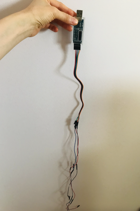
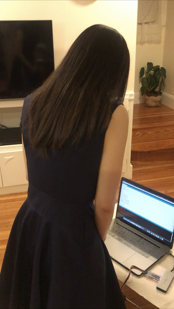
Testing was the fun part! I had prepared a +/- 1.60 meter (~ 5 feet 3 inches) long wire for the connection since the system was still powered by FTDI 😆.
My mother helped start the system on the back of my dress and recorded me testing. I could feel the vibration motor buzz at me if my back was leaning very forward (Gyroscope X, Y, Z was set at a threadshold). In the future, It may be nice to replace the woven fabric with a knit fabric and include the stretch sensor in my project to evaluate the horizontal movement of my back via the pull of the fabric, which would help increase the accuracy of the system.
Bill of Materials (BOM)
| Item | Quantity | Source | Unit Price (USD, $) | Total Cost (USD, $) |
|---|---|---|---|---|
| FTDI (1x6 male header connector) | 1X | 3DExperience Lab | 0.60 | 0.60 |
| "I2C connectors" (1x4 female header connector) | 3X | 3DExperience Lab | 0.74 | 2.22 |
| 3.3V 1A Regulator (ZLDO1117G33DICT-ND) | 1X | 3DExperience Lab | 0.34 | 0.34 |
| Capacitor 10uF (587-3007-1-ND) | 1X | 3DExperience Lab | 0.24 | 0.24 |
| Capacitor 1uF (445-1423-1-ND) | 1X | 3DExperience Lab | 0.07 | 0.07 |
| Capacitor 0.11uF (399-4674-1-ND) | 1X | 3DExperience Lab | 0.12 | 0.12 |
| Resistor 10K ohm (311-10.0KFRCT-ND) | 3X | 3DExperience Lab | 0.01 | 0.03 |
| Resistor 1K ohm (311-1.00KFRCT-ND) | 1X | 3DExperience Lab | 0.01 | 0.01 |
| Resistor 0 ohm (311-0.0ERCT-ND) | 7X | 3DExperience Lab | 0.00477 | ~0.03 |
| Red LED (160-1167-1-ND) | 1X | 3DExperience Lab | 0.13 | 0.13 |
| Tact Switch (SW262CT-ND) | 2X | 3DExperience Lab | 0.84 | 1.68 |
| ESP32-WROOM-32E (1965-ESP32-WROOM-32E(8MB)CT-ND) | 1X | 3DExperience Lab | 2.80 | 2.80 |
| MPU6050 Acceleromter/Gyroscope module | 1X | Amazon.com | 5.39 | 5.39 |
| DRV2605 Haptic Controller module | 1X | Amazon.com | 11.44 | 11.44 |
| Vibration Motor | 1X | Amazon.com | 0.866 | 0.866 |
| Linen fabric and lining | 3 yards each | local fabric store | 2.99 per yard | 17.94 |
| Polyester Thread (547 yard per roll) | 2X | local fabric store | 4.99 | 4.99 |
| Invisible zipper | 1X | local fabric store | 0.92 | 0.92 |
| Total | ~50 |
Files
Please find below all the files that I made for this project.
- CLO3D Fashion Design Files
- Laser Cut Textile Files (.ai file for laser cutting)
- Brooch SOLIDWORKS and .STL File
- Electronics Design and Production Files (KiCad, Illustrator)
- Arduino Sketch for Blynk BLE
- Networking with Input and Output Devices
- Final Project Summary Slide: presentation.png
- Final Project Video: presentation.mp4
- Supplemental Video for Systems Testing: project-testing.mp4