
This work is licensed under a Creative Commons Attribution-NonCommercial-ShareAlike 4.0 International License
Activity Log 4: App Interfacing and Networking
Summary
After screening different tools (Bluetooth Serial, MIT App Inventor and Blynk), I chose to use Blynk and Arduino IDE to develop the bluetooth application (BLE) for my system. I find the Blynk user interface easy to work with and that the BLE feature of the app works for iOS and Android phones. When developing the Arduino sketches, I referred to Adafruit's libraries for MPU6050 and DRV2605 modules. I also used "spiral development" throughout the experience. This post details my process and how I achieved the final result.
Setting Up Blynk
Blynk is a platform to control Ineternet of Things via iOS and Android apps. I liked that this app has already set up the ESP32 Dev Board as one of the devices, what's more, its BLE app works for both iOS and Android phones. As I was new to making application, I decided to work on this exercise in spirals. Currently, I was able to use the app the turn the LED on/off, as well as to monitoring the gygroscope readings.
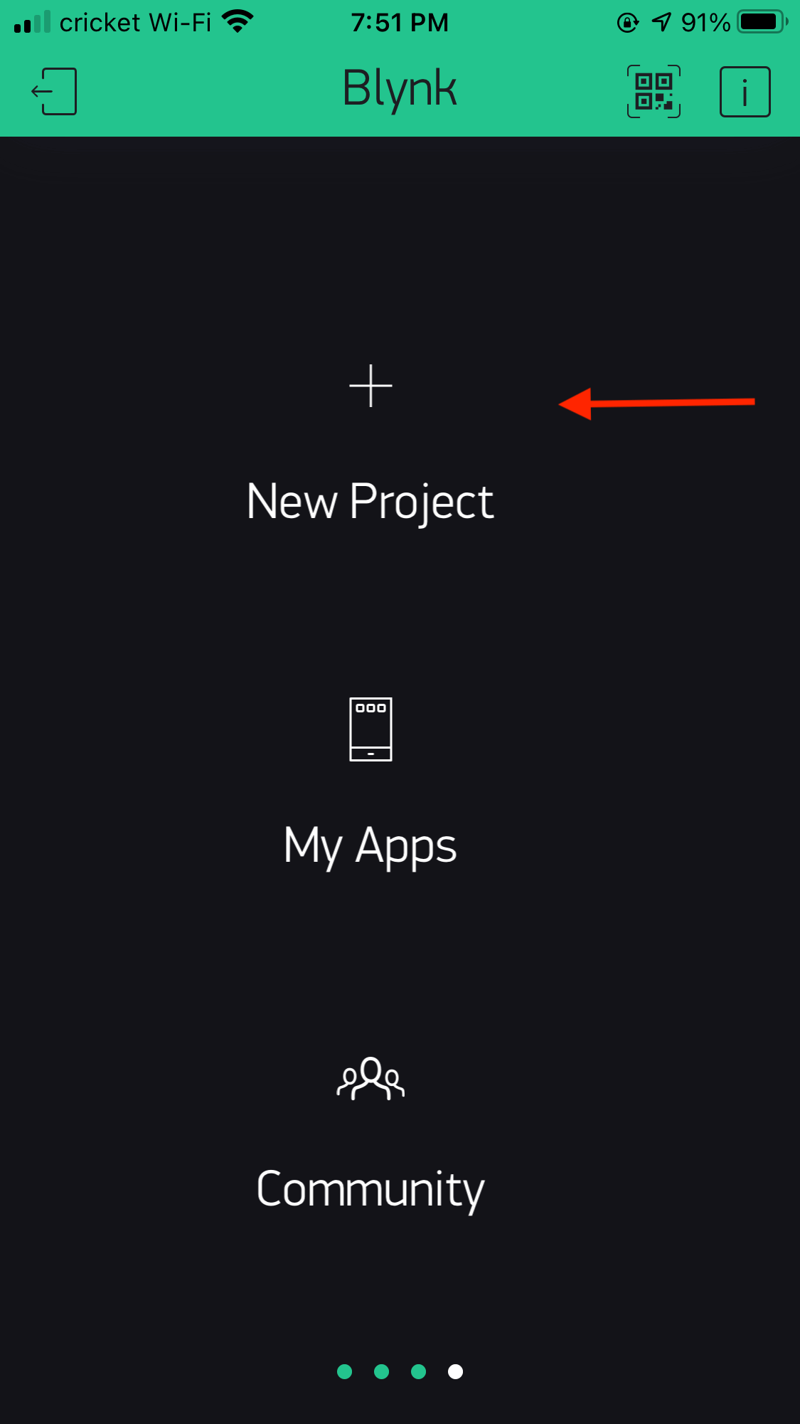
After downloading and installing the Blynk app on my phone, I pressed New Project.
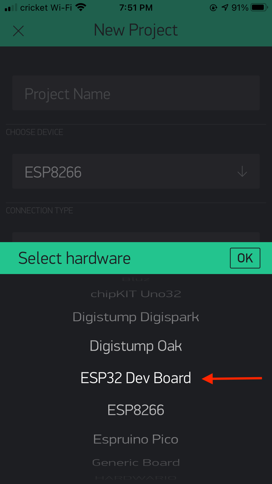
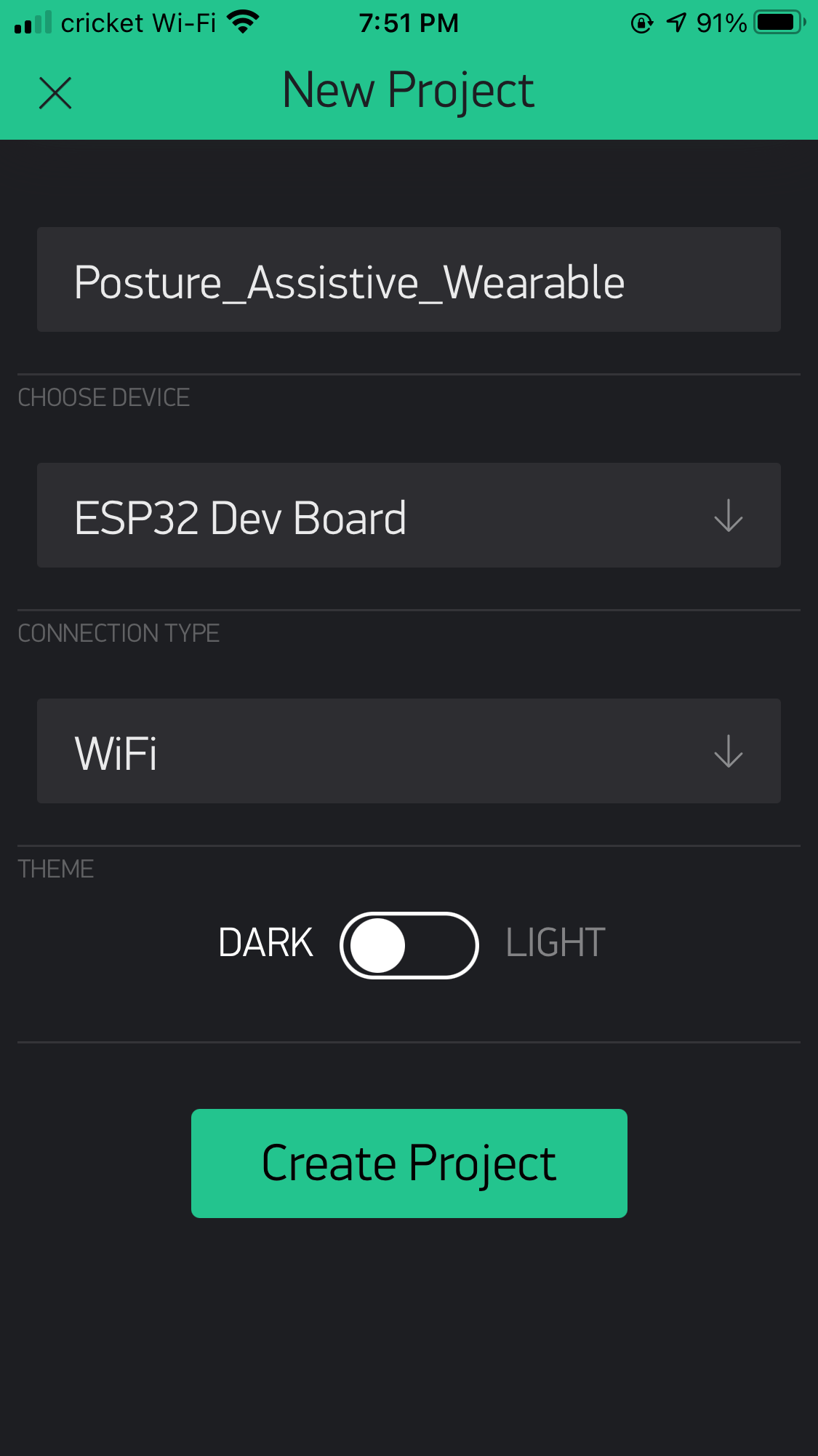
I entered the project name, and chose ESP32 Dev Board as the board, and WiFi as the connection type.
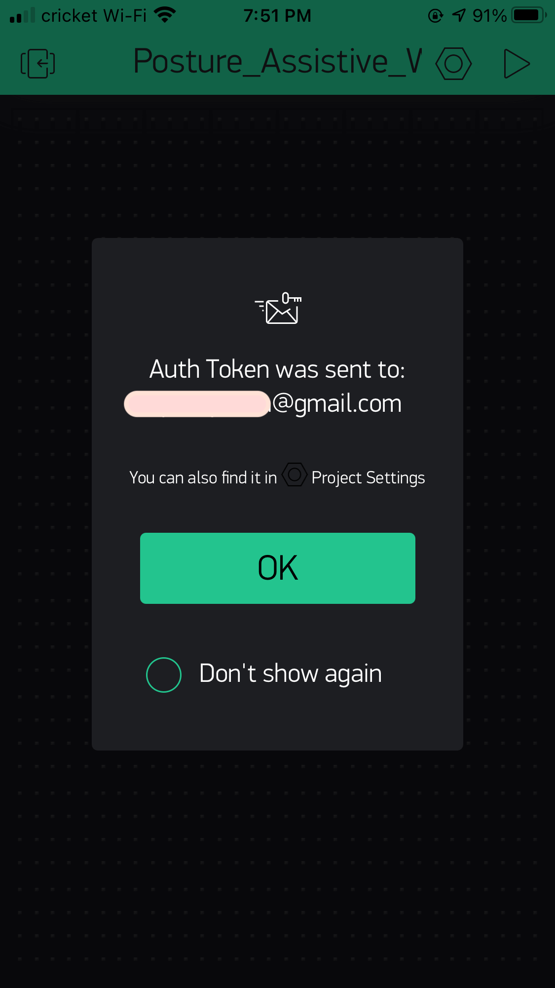
After that, the app will send an Authorization Token to my email. This token is important because we will need to input this information in the Arduino sketch.
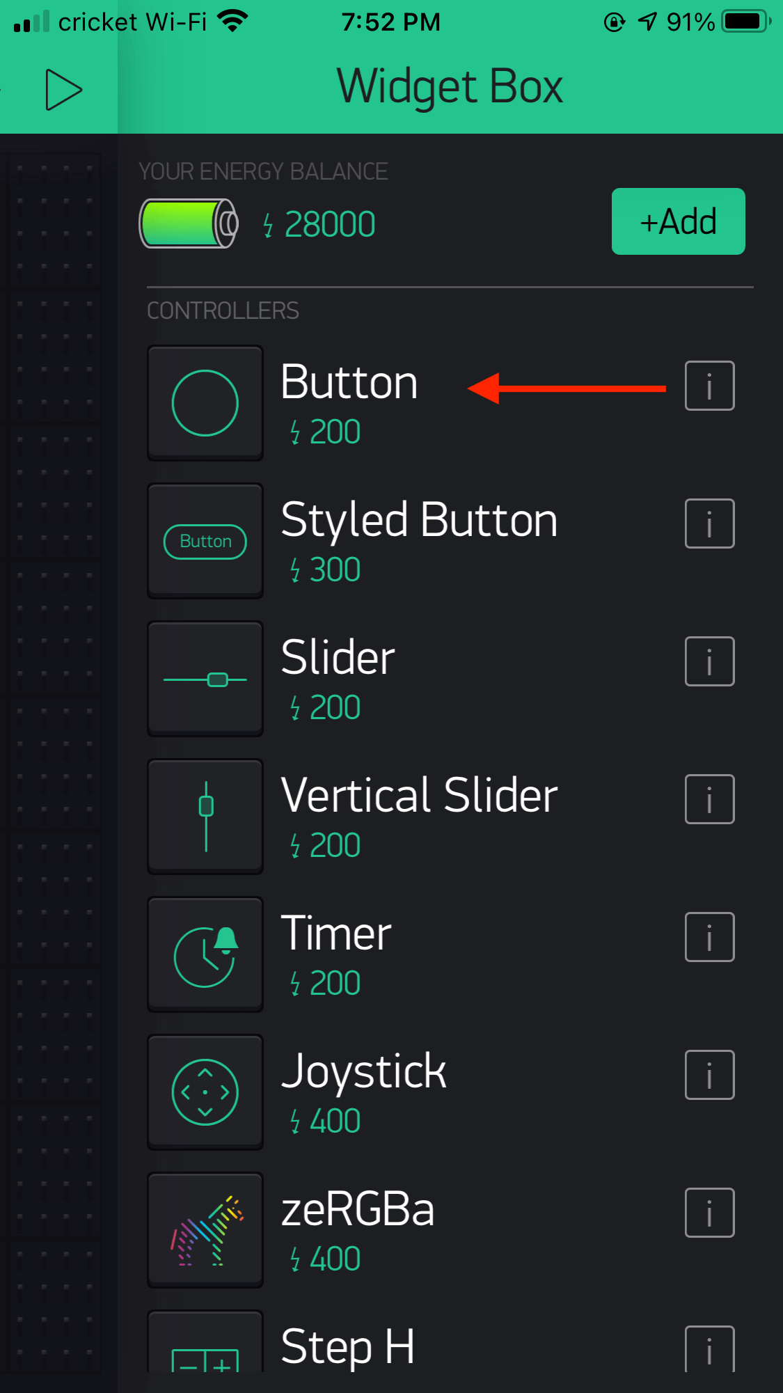
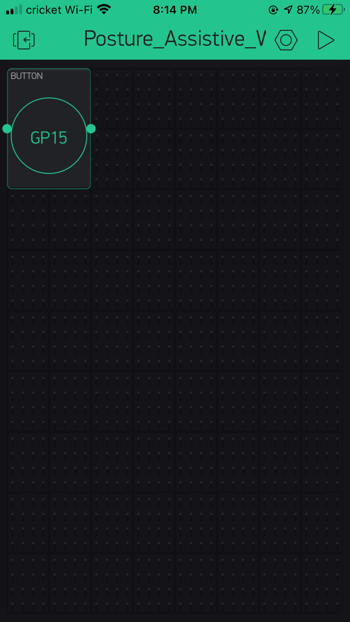
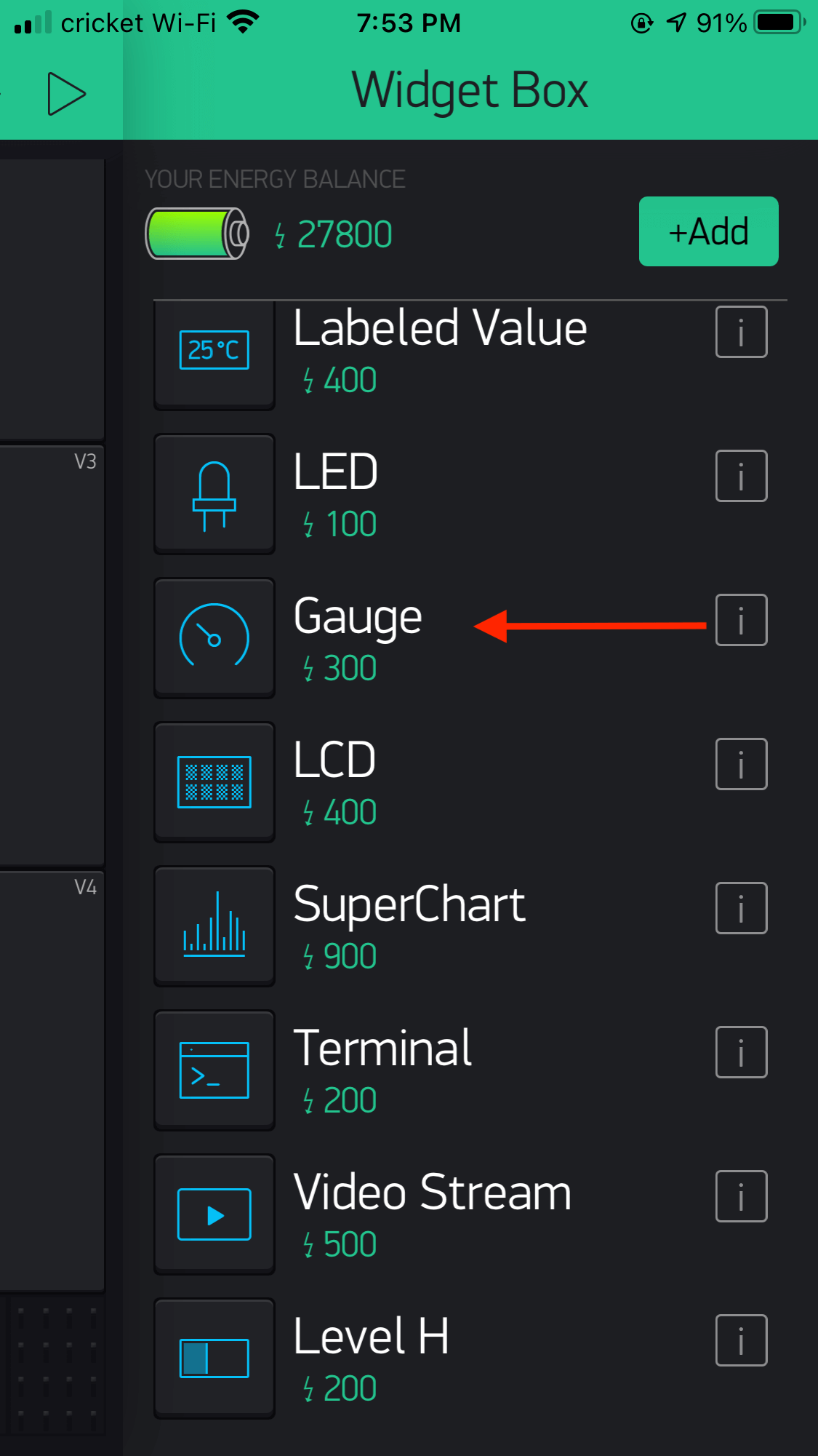
I touched the blank space on the Blynk screen and the Widget Box appeared. I wanted to be able to control the power indication LED on my board, so I picked a Button.
I touched the blank space on the Blynk screen and the Widget Box appeared. I wanted to be able to control the power indication LED on my board, so I picked a Button.
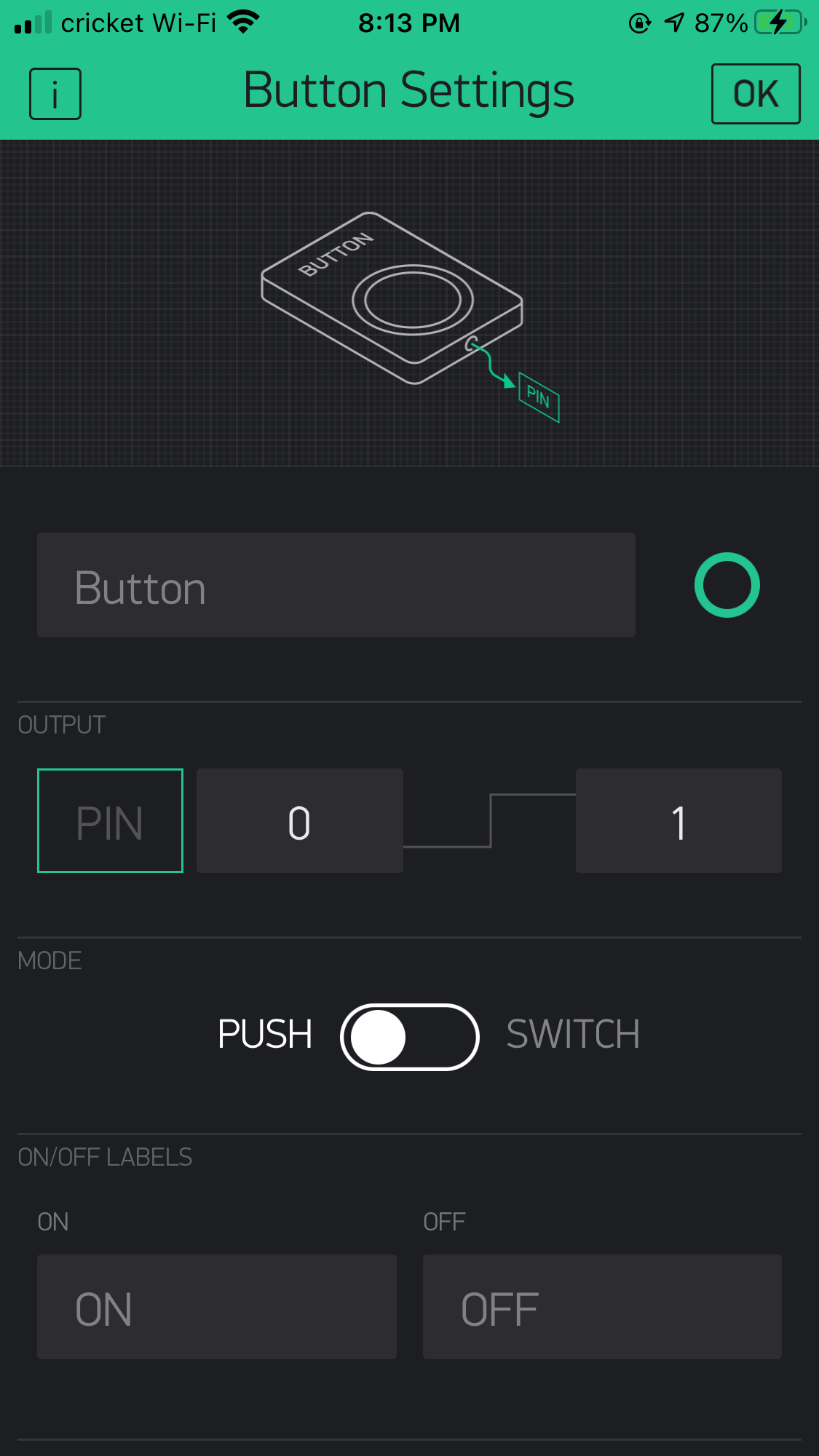
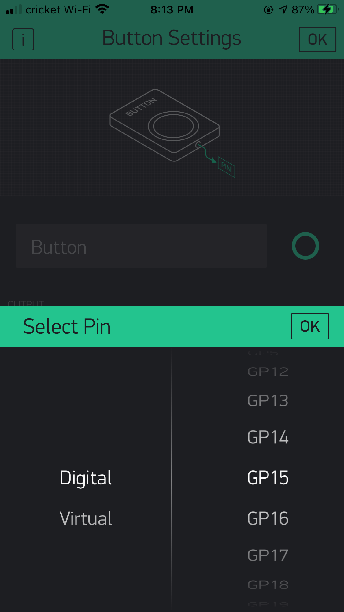
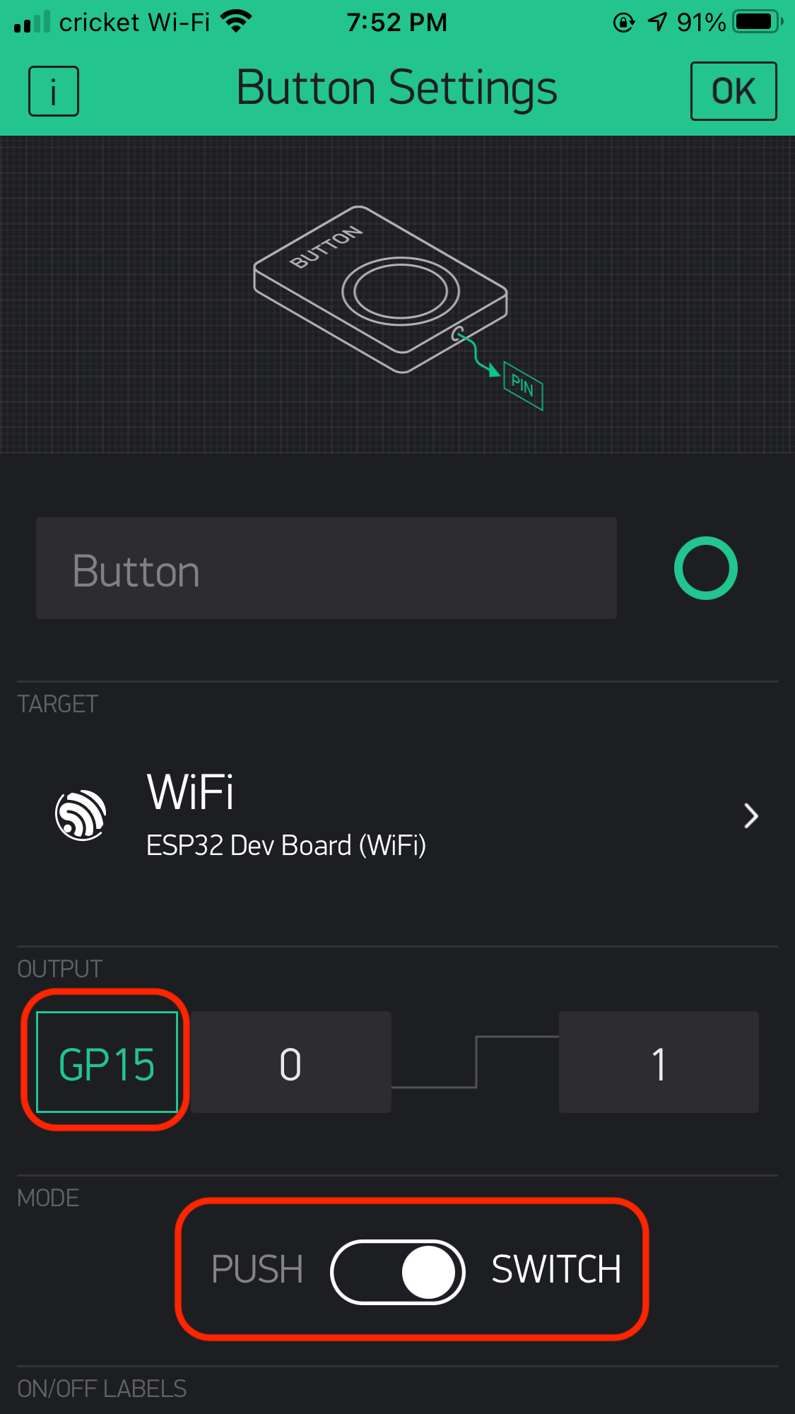
I learned that we can control over Digital pin or Virtual pin. Since I already set up GPIO 15 in my ESP32-WROOM board as the LED pin, I picked Digital > GP15 and set it at a Switch mode.
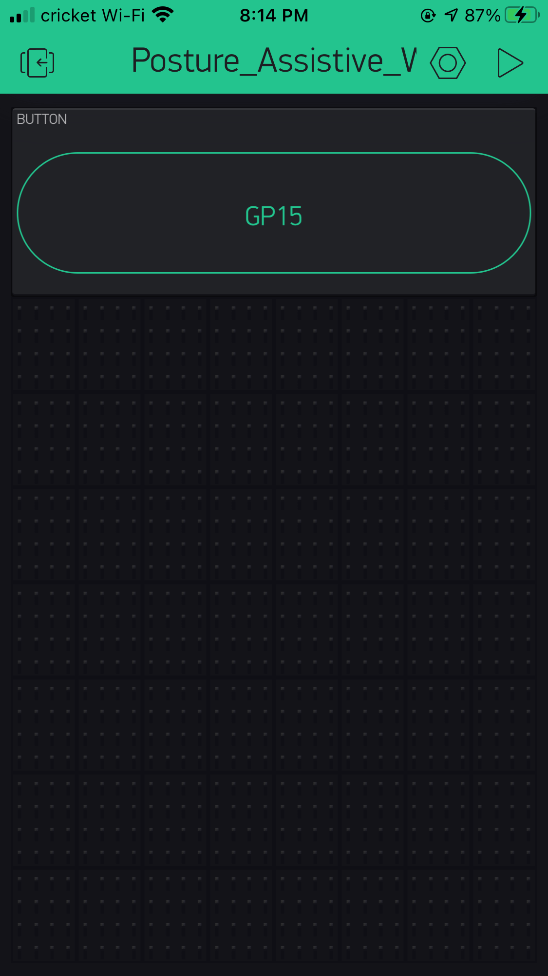
And this is how it looked after adding the button. I dragged the green dot to made the button longer.
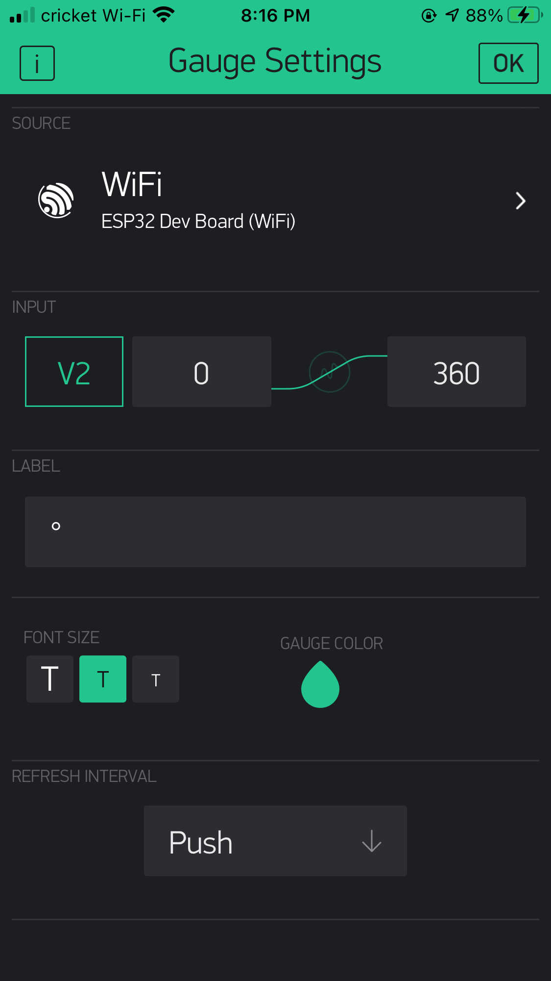
After adding the button, I wanted to work on something related to my I/O devices. I found this tutorial very helpful as it taught me step-by-step how to get the MPU6050 gyroscope readings on the app. This tutorial was designed for an ESP8266 NodeMCU microcontroller, however I only needed to make small adjustments such as changing the libraries. Here is a sample image taken from my phone for this feature.
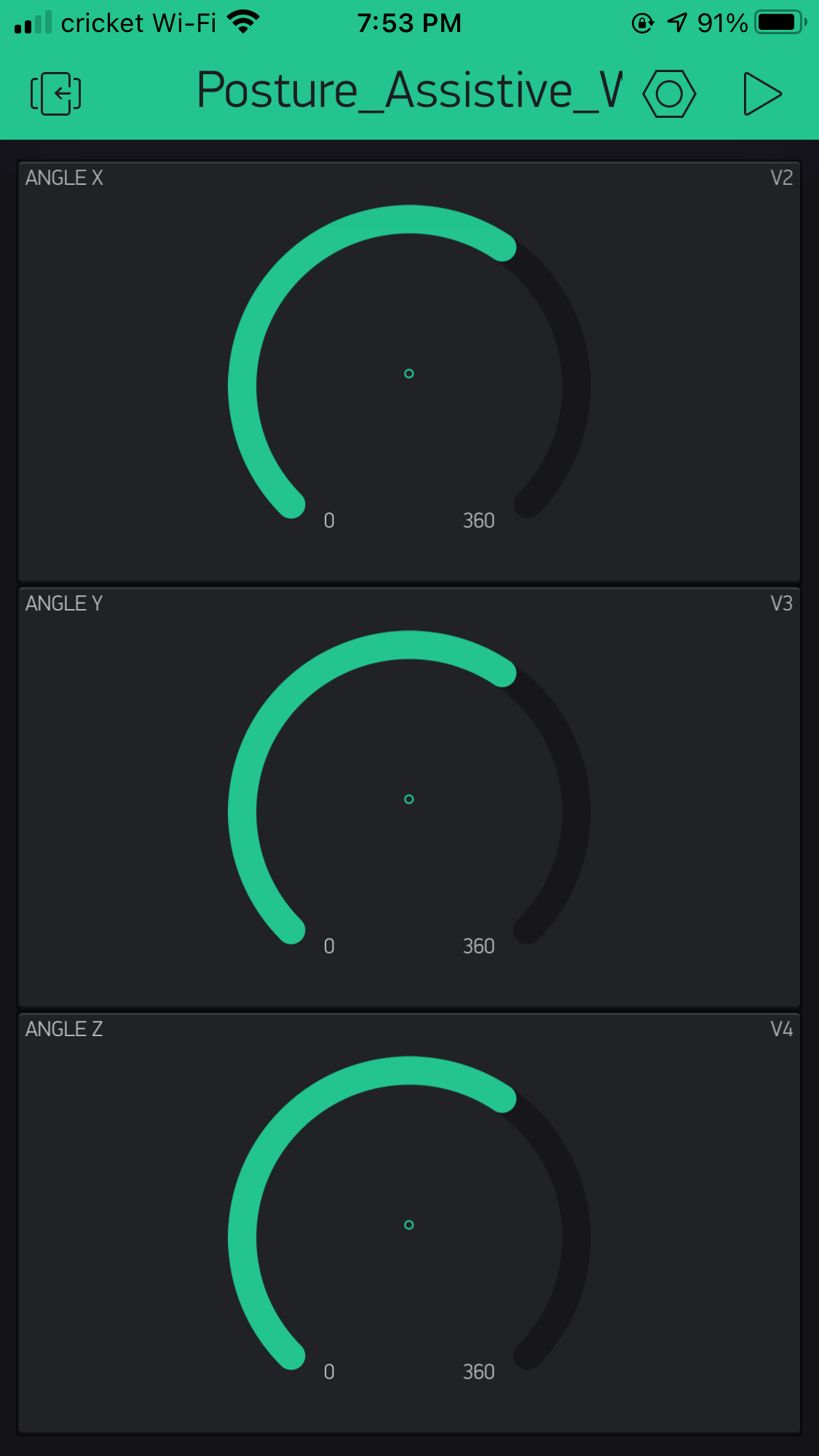
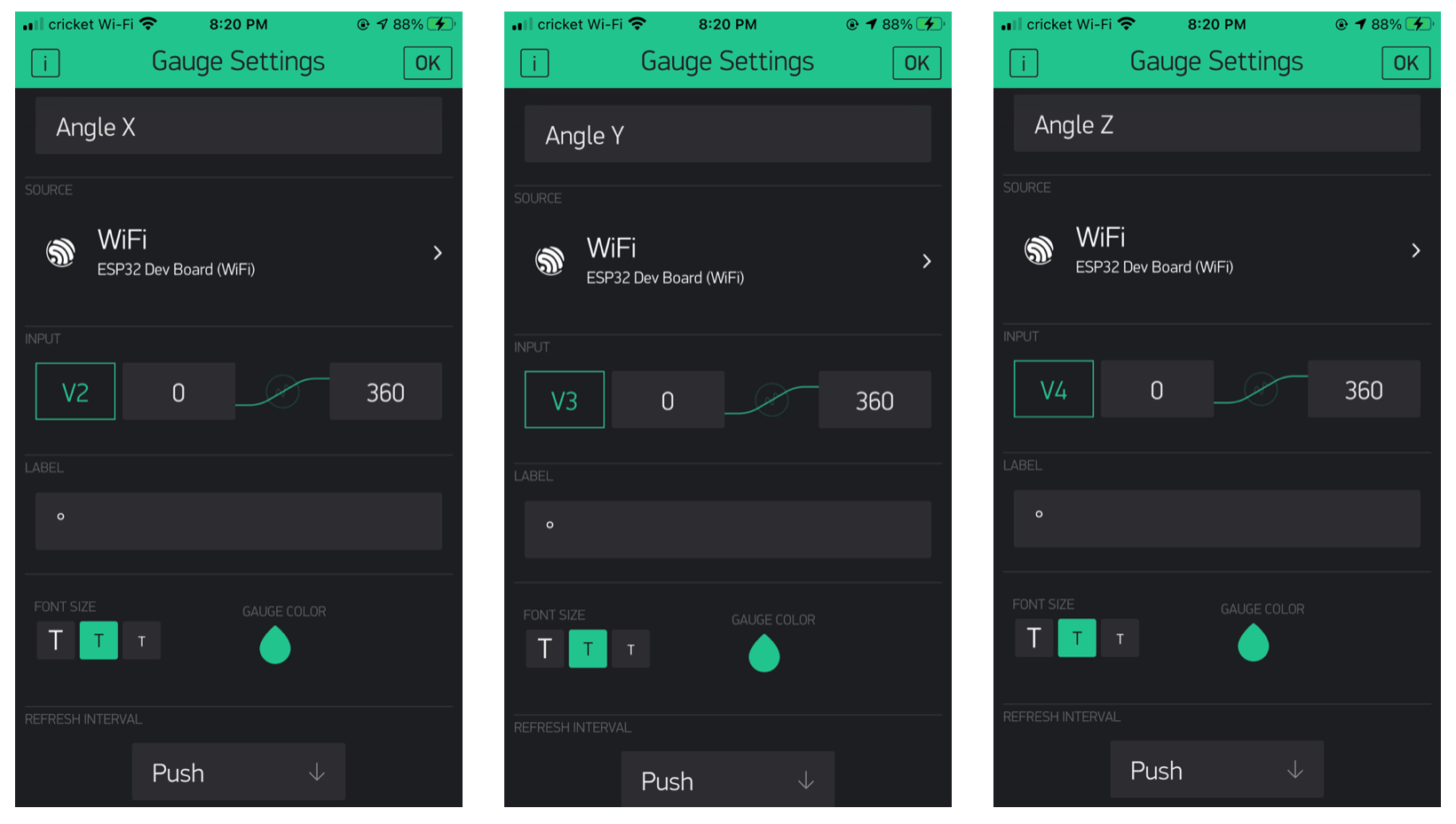
I followed the tutorial to add three gauges to the main screen, and named them as AngleX, AngleY, and AngleZ accordingly.
The MPU6050 accelerometer/gyroscope uses the I2C communication to interface with the ESP32-WROOM. However in this case, since I didn't have a designated pin for the rotation of X, Y, Z axis, I would use the Virtual pins.
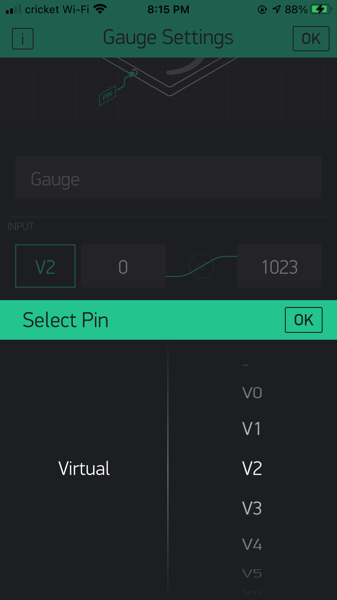
In the app, I picked degree as the unit because I wanted to measure the tilt angles of the MPU6050. According to the tutorial, the output of the gyroscope are degrees per second, so in the Arduino sketch (next section of this activity log), I would need to integrate the angular velocity to get the tilt angle.
And this is how the three gauges looked.
Setting Up Arduino IDE
After setting up the Blynk App, I then proceeded to work on the Arduino sketch. Here is an screen shot of the final sketch:
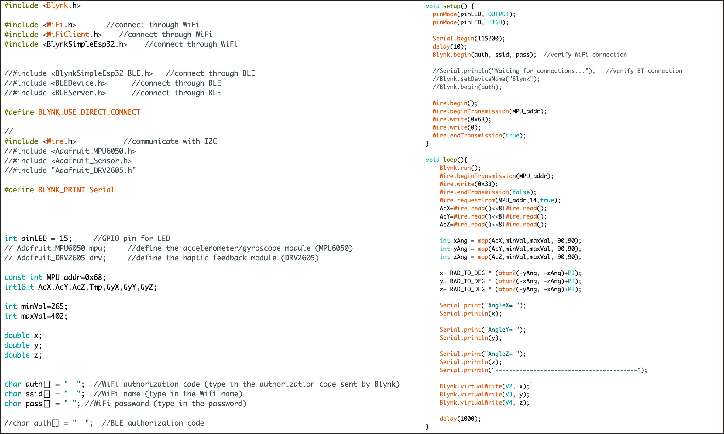
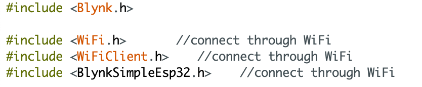
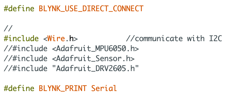
I started by downloading the Blynk library to compile the code (Tools > Manage Libraries). In my case, I referred to the Blynk ESP32 WiFi example sketch (Arduino IDE > Files > Examples > Examples from Custom Libraries > Blynk > Boards_WiFi > ESP32_Wifi), and learned that I would need the libraries as shown in the image below. Please note that since the MPU6050 module communicate with I2C, I also needed to include the Wire.h library as it was designed for this communication.
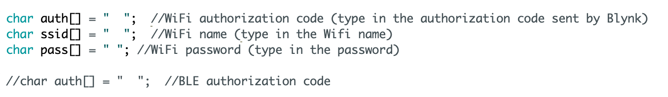
With Blynk, I would need to enter the Autorization Token that I received earlier. Different Blynk app has a different token, but a nice thing about the app is that, we can always resend / refresh to create a new token when working on the app.
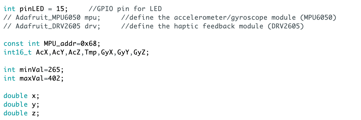
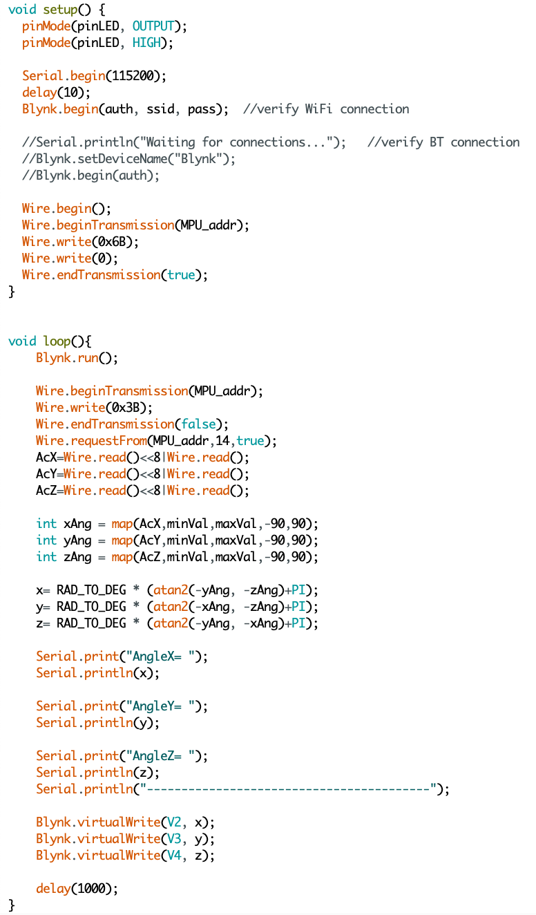
This image shows the pre-setup of the sketch. Note that the MPU_addr=0x68 is indicating the I2C address for MPU6050 is 0x68, and this could be found in this in this document.
Here is an image showing the setup and loop of the sketch. As mentioned previously, I wanted to measure the tilt angles of the MPU6050. so I could achieve this by integrating the angular velocity in this Void loop() step.
Testing Blynk
Testing LED and Gyroscope
I started by testing the app on my ESP32 FR1 board, and here is a short video showing the testing process. After uploading the sketch, I was able to turn on and off the LED on the board. While filming the process with another phone, I lay the board on my computer. And as I nudged the board, the gauages in the app dialed accordingly.
Blynk reading vs. Serial monitor reading
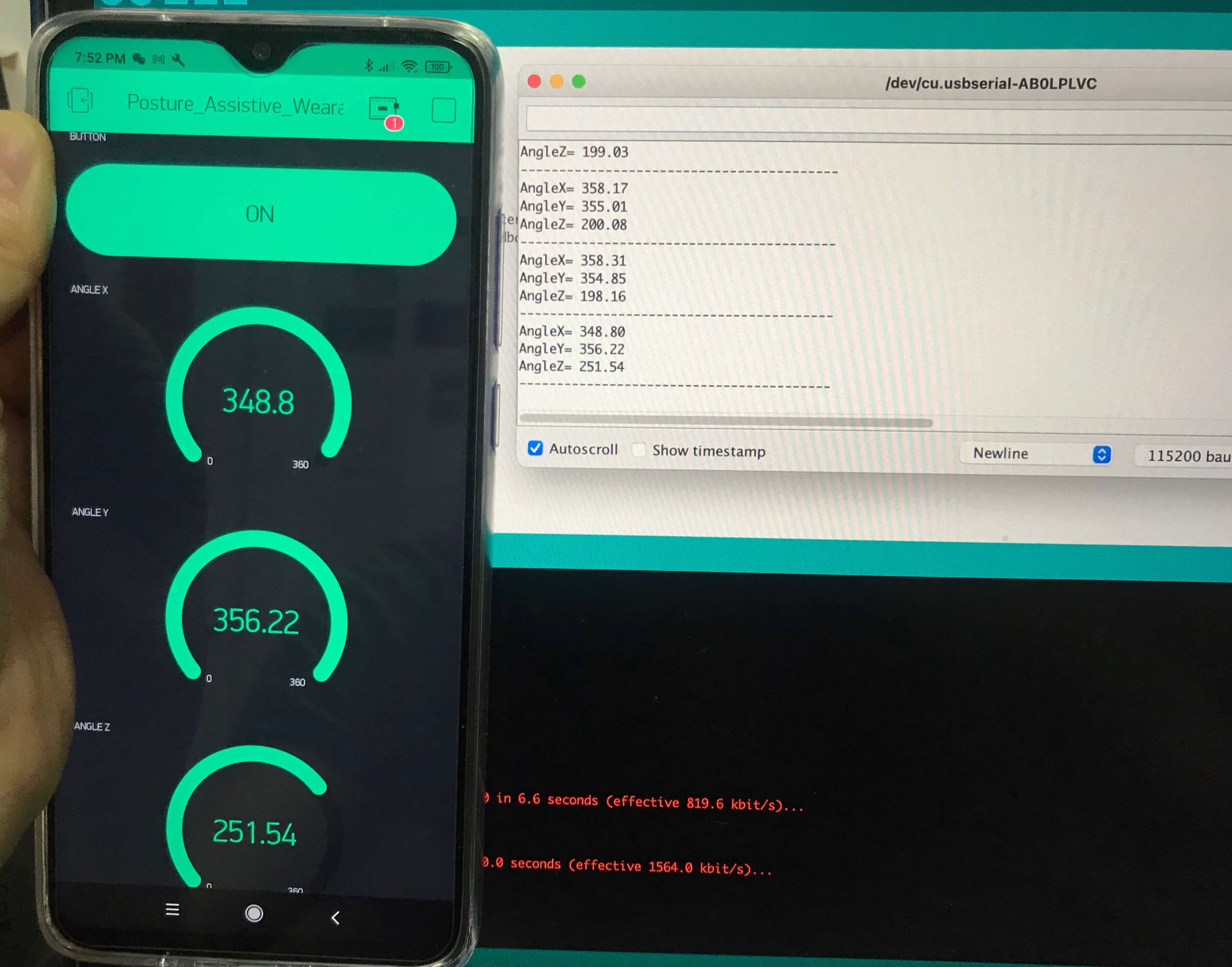
The Arduino sketch above allowed the Serial monitor to get the real-time reading too, so I was able to evaulate how the app performed by comparing them to the Serial monitor readings. As shown in the image below, the readings from the app matched to the last readings from the Serial monitor, and thus the app was able to read real-time gyroscope data.
Networking and Systems Integration
After confirming my input devices worked, I proceeded to add the output device, which was the vibration motor. In my project, I used Adafruit's DRV2605 Haptic Feedback board, so I referred to their documentaiton for this board when developing the sketch.
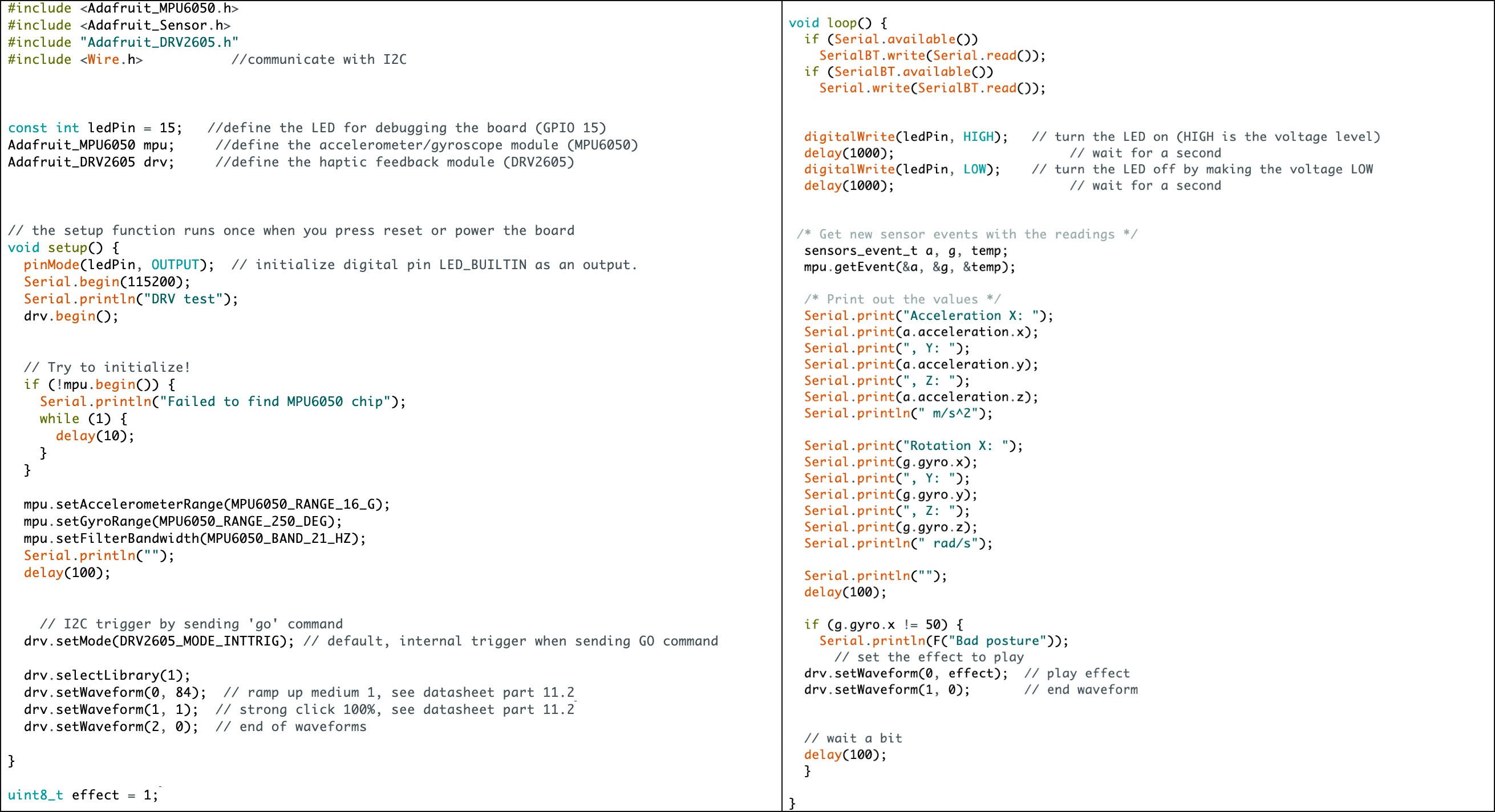
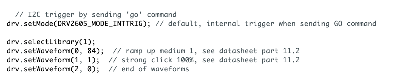
In this system, the input device was the MPU6050 accelerometer/gyroscope module, and the output device was the Adafruit DRV2605 haptic feedback module. Both modules utilized I2C communication so I recalled the Wire.h library. Adafruit has provided some examples to test the haptic feedback module, and the sketch below was developed upon their basic example. In the example, I was allowed to test the 103 vibration settings in the DRV2605. I wanted my system to have a low to high vibration buzz, then stop, so I had the following in the Void Setup().
My flexible PCB was not able to connect to the Blynk app, however I was able to test it on this sketch. Since I wanted to improve the PCB design post-fabacademy, I decided not to sew the flexible PCB into the lining. In the new approach, I sewed a "welt pocket" inside the back lining to serve as the nesting place for the flexible PCB. As the flexible PCB has a taped back, it can be removed easily for safe laundry.
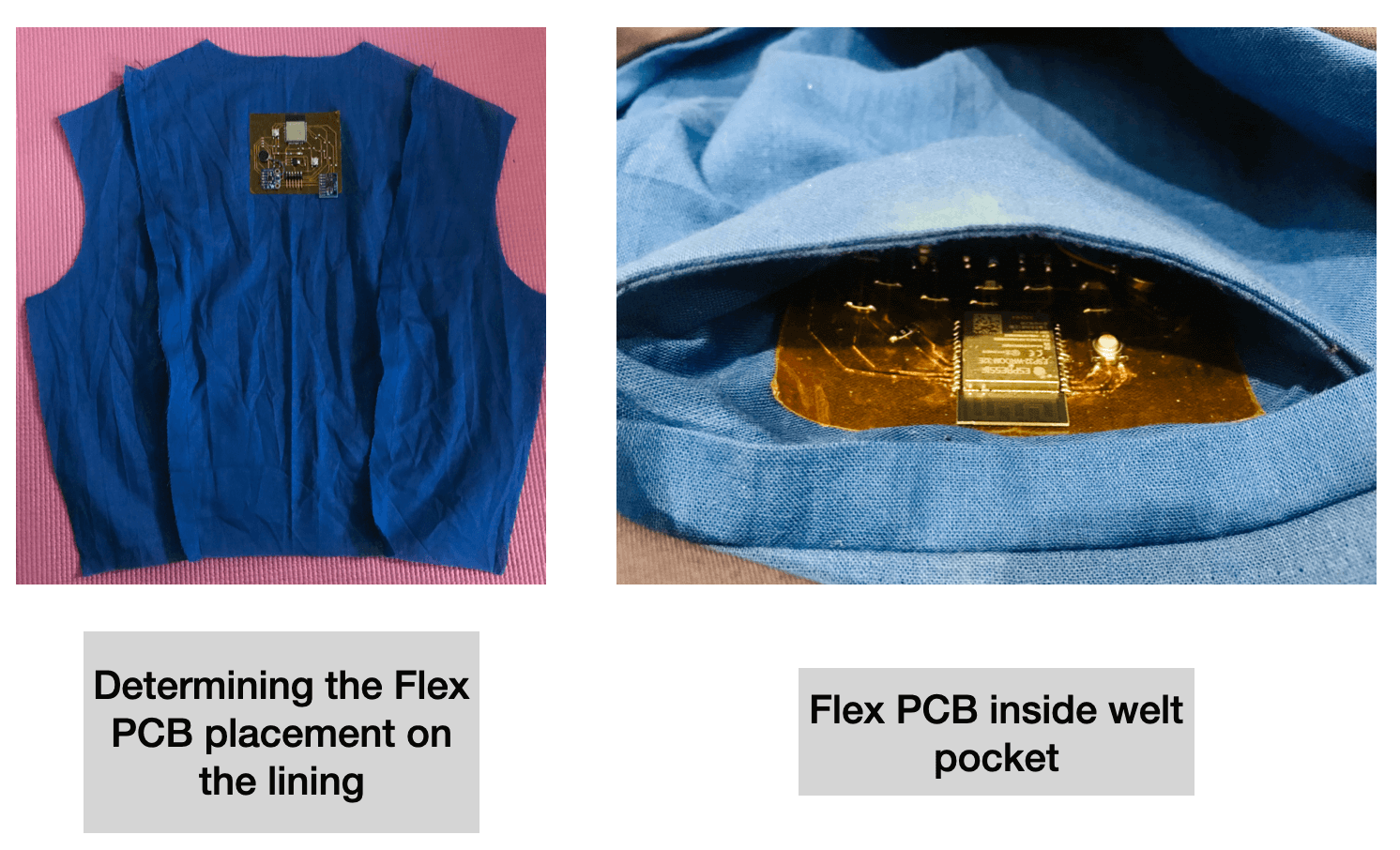
The first image above shows the placement of the flexible PCB on the center back lining. This is towards the upper back, which is the location for noticelly rounded or protruding for poor posture. The second image shows the flexible PCB nesting in the welt pocket of back lining. Since the system was still powered by FTDI, I had left some open space in the bottom of the pocket and had prepared a +/- 1.60 meter (~ 5 feet 3 inches) long wire for the connection.
Here is a video showing the result of the functional test. My mother helped start the system on the back of my dress and recorded me testing. Because the flexible PCB was not as senstive as the FR1 PCB, I had to calibrate a few times to get the threadhold right. I could feel the vibration motor buzz at me if my back was leaning very forward. In the future, It may be nice to replace the woven fabric with a knit fabric and include the stretch sensor in my project to evaluate the horizontal movement of my back via the pull of the fabric, which would help increase the accuracy of the system.
Files
Please find below all the files that I made for this project.