
This work is licensed under a Creative Commons Attribution-NonCommercial-ShareAlike 4.0 International License
Week 7: Computer-Controlled Machining
Mar 16, 2021Summary
This week's assignments
- Group assignment:
- Test runout, alignment, speeds, feeds, and toolpaths for your machine ✔
- Document your work (in a group or individually) ✔
- Individual assignment:
- Make (design + mill + assemble) something big:
- Document how you designed your object (something big) ✔
- Document how you made your CAM-toolpath
- Document how you made something BIG (setting up the machine, using fixings, testing joints, adjusting feeds and speeds, depth of cut etc.)
- Describe problems and how you fixed them
- Include your design files and "hero shot" photos of the final object
Resources Used
- Software: SOLIDWORKS, VCarve Pro
- Hardware: ShopBot
Skills Gained
- 3D modeling, CNC operation
My Weekly Schedule
Introduction to CNC Machining
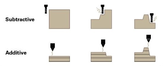
Computer-Controlled machining is a subtractive form of manufacturing, which is opposite of 3D printing (additive manufacturing). In subtractive manufacturing, the material is removed from the workpiece to produce the final design shape layer by layer, so this is one similarity to 3D priniting, which is the add material to the workpiece layer by layer. Other subtractive manufacturing process that I have learned so far included laser cutting and PCB milling.
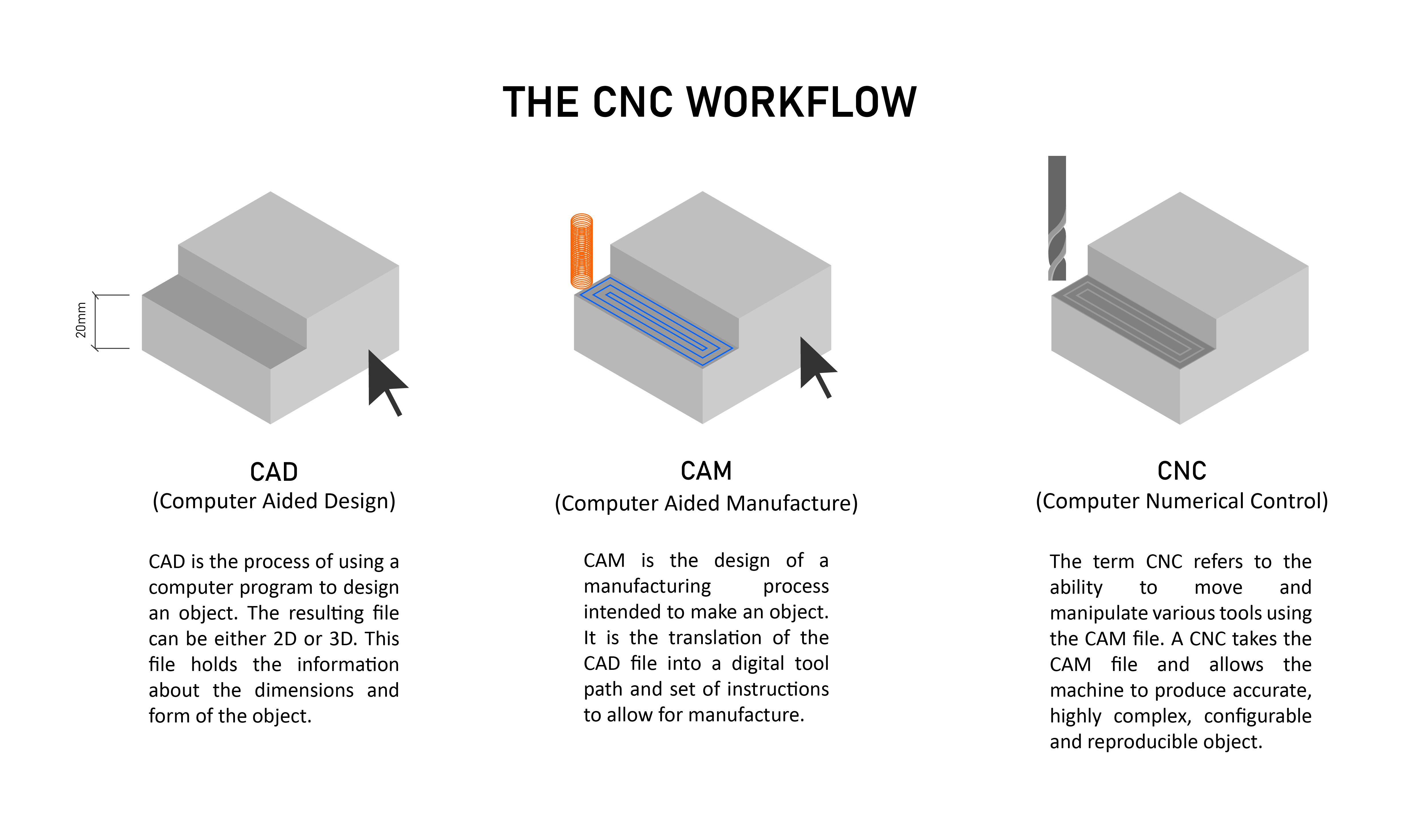
The process for CNC machining starts with computer-adied design (CAD), next the dimensional data (saved in .dxf files) is exported to a computer-aided manufacturing (CAM) software (i.e. VCarve Pro), which generates the toolpaths that the CNC router machine (i.e. ShopBot) understands. In the end, the CNC router reads the generated toolpaths and conducts a series of machine movements along different axes.
Safety Training
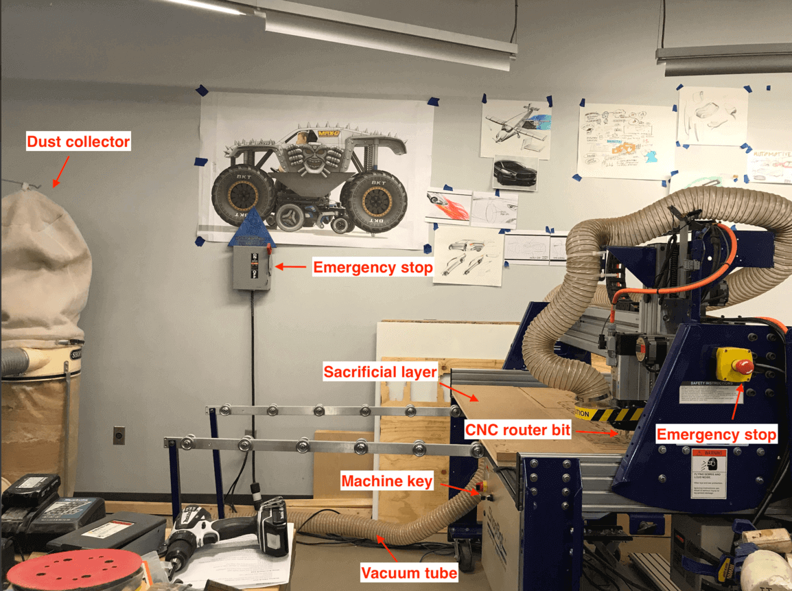
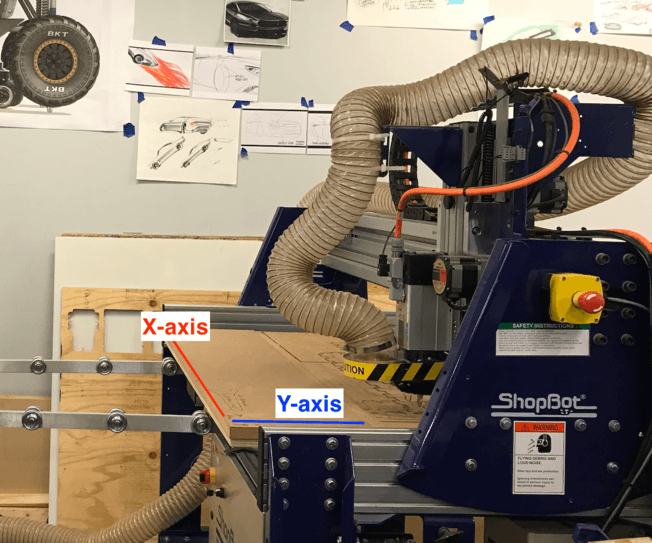
On Thursday, we assembled at 3DExperience Lab to learn how to operate a ShopBot CNC router from our instructor, Spencer. The one at the lab is a 3-axis full-size machine, with a 96" x 48" work area.
During the Global Lecture, Neil told us that the CNC router is the most dangerous machine in a Fab Lab, so I must be extra precautious when operating this machine:
- Do not operate unless I have been properly trained to do so.
- Never work alone. Never work when I am tired.
- Must wear safety glasses and hearing protections.
- Must wear approprite apparel: no loose clothing or jewerly, closed-toes shoes, hair tied back.
- Always keep aisles, exits and access to emergency equipments clear at all times
- Verify the overall condition of the equipment and the material being used
- Double check all toolpaths before hitting the "start" button.
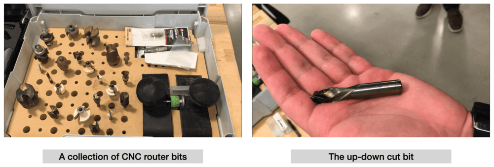
CNC Router Bits
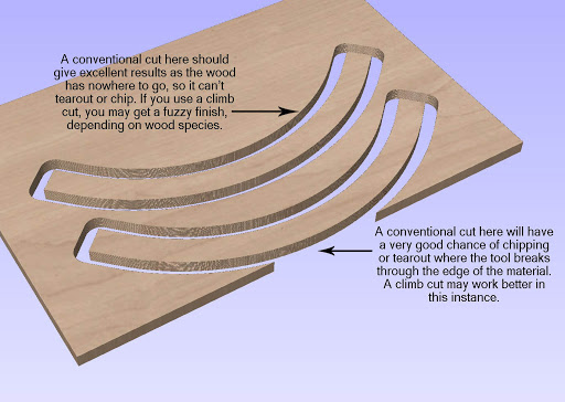
One important concept was about conventional milling (up) and climb milling (down). The difference between these two techniques was the relationship of the roation of the cutter to the direciton of the feed. Climb milling is generally suggested to machine parts since it reduces the load from the cutting edge, so it leaves a better surface finish and improves tool life.
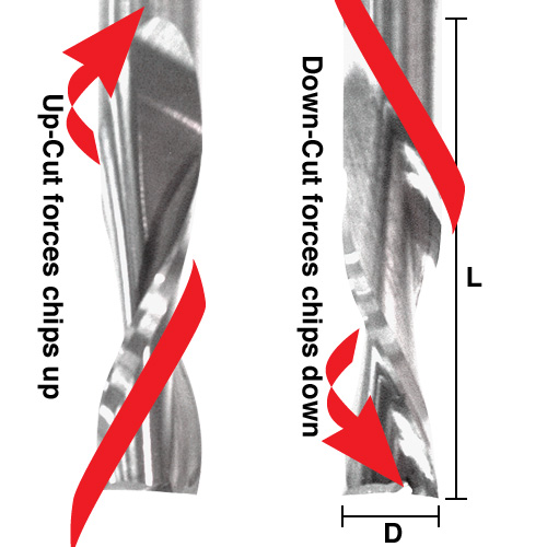
I learned that carbide spiral bits are more popular because they can give a very clean cut. There are two major types of spiral bits: up-cut bit vs. down-cut bit. A down-cut bit will leave a clean edge on top but a rough edge on the bottom; while an up-cut bit will accomplish the opposite. As we most likely will be using the down-cut bits for our assignments, our finished workpieces would have a clean top edges, but we most likely would need to sand the bottom.
During the training, Spencer showed us a collection of all the bits he had, and shared information such as up-cut bits, down-cut bits and v-bits...etc. There was one bit that was particularly interesting: the up-down cut bit (also called the "compression spiral"), which gives a very clean finish from top to bottom for the working piece!
Helpful Resource: Cutting Tools
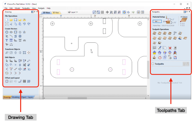
VCarve Pro
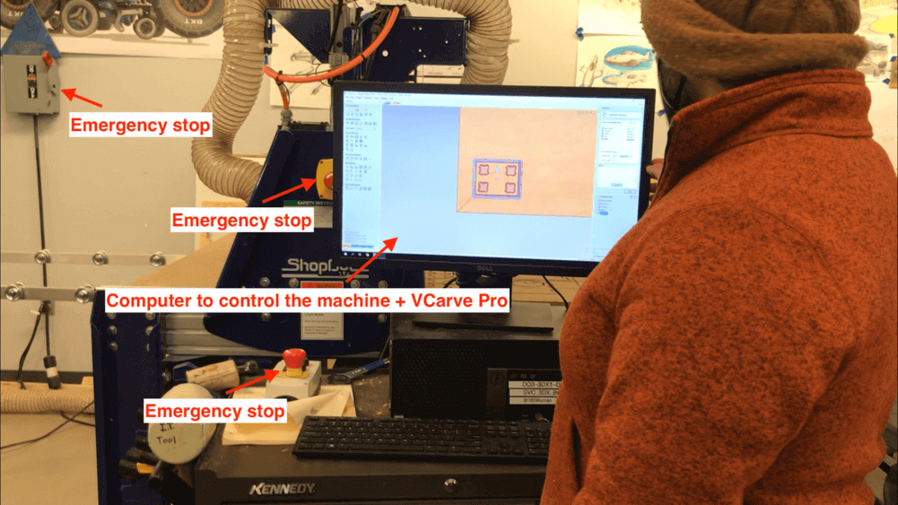
VCarve Pro is the CAM software for ShopBot. A few days before the class, Spencer has recorded a video on how to use Vcarve Pro, and I found it helpful because I knew where to find the different tabs on the CAM software by the time I learned how to use the ShopBot on Thursday.
In general, the two tabs that we would use in VCarve was the Drawing tab for 2D view and the Toolpaths tab for 3D view. We can sketch our design on the 2D view, but we can also import the vector file (.dxf) for our CAD design. We were told that VCarve does not accept .svg filea.
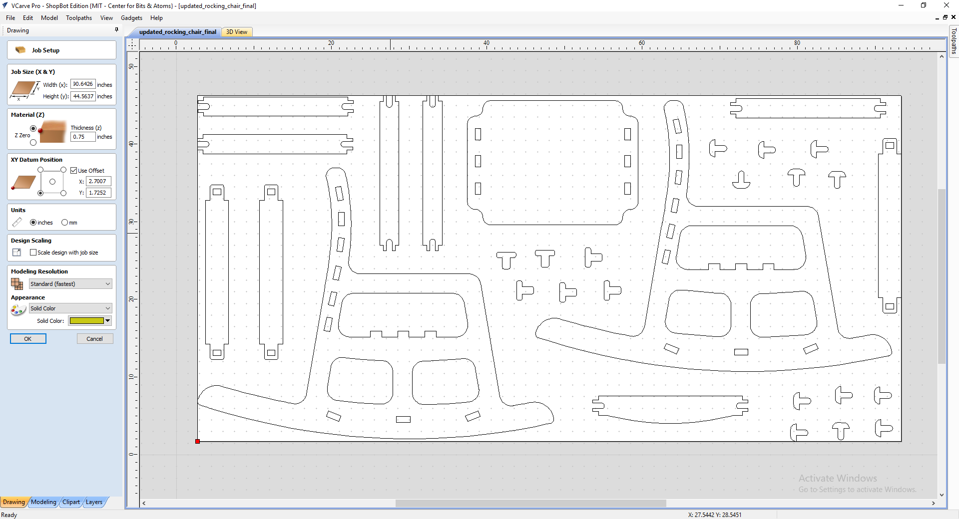
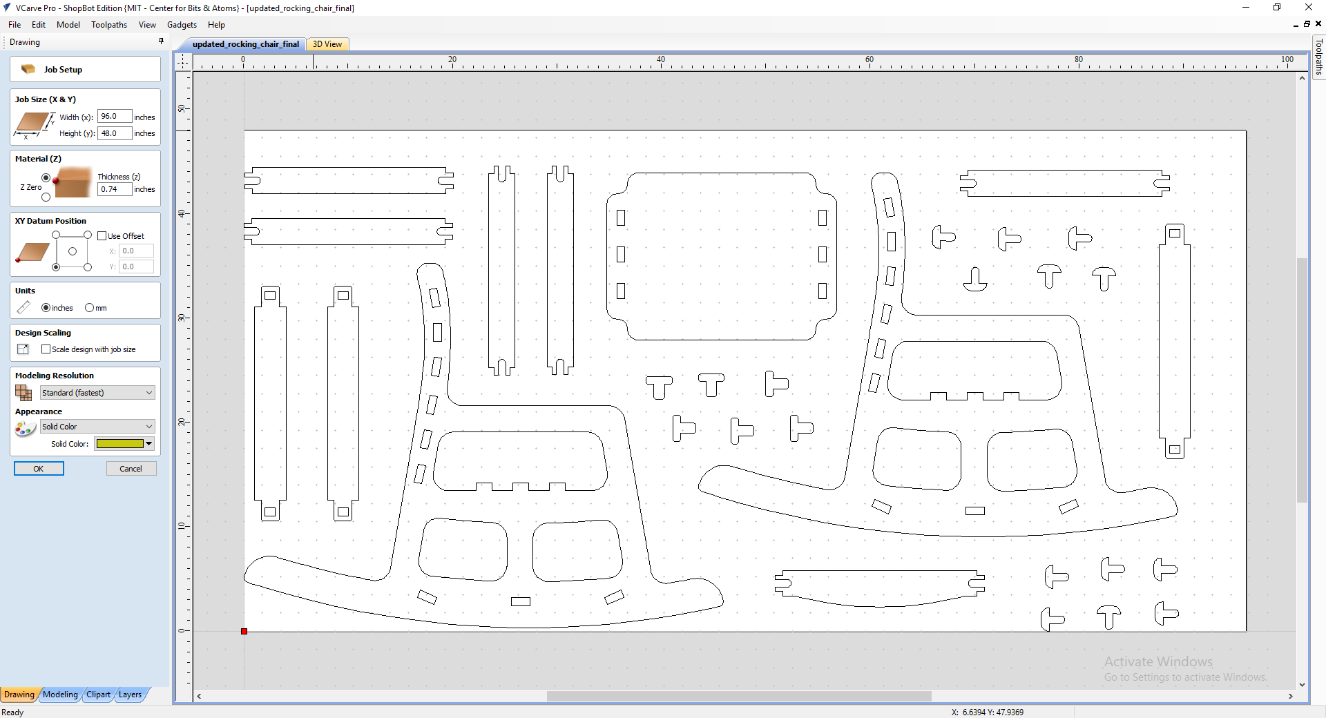
Job Setup Screen:
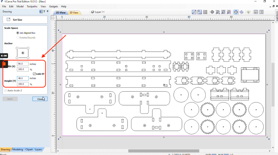
After importing the .dxf file into VCarve Pro, we need to set the job size and determine the XY datum position (origin). Spencer suggested us to set the job size to the size of the entire bed, which was 96" x 48". The thickness of the material would need to be measured. The XY Datum position is the origin for the job, and it would be at the left bottom corner.
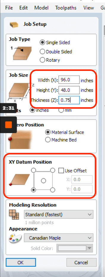
Setting the correct unit system is very important, becasue it will affect the whole job if we choose the wrong unit, either by a factor of 25.4 (due to incorrection in setting dimensions) or by a factor of 60 (due to incorrection in choosing speeds).
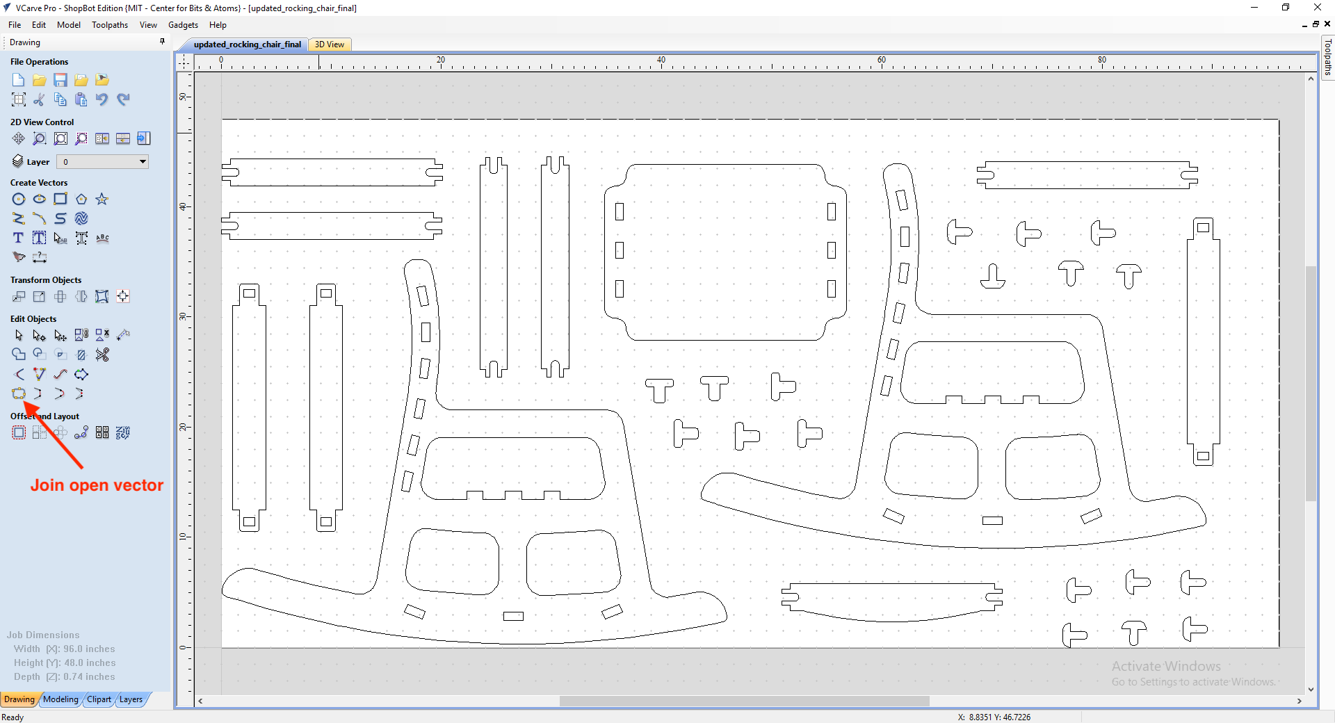
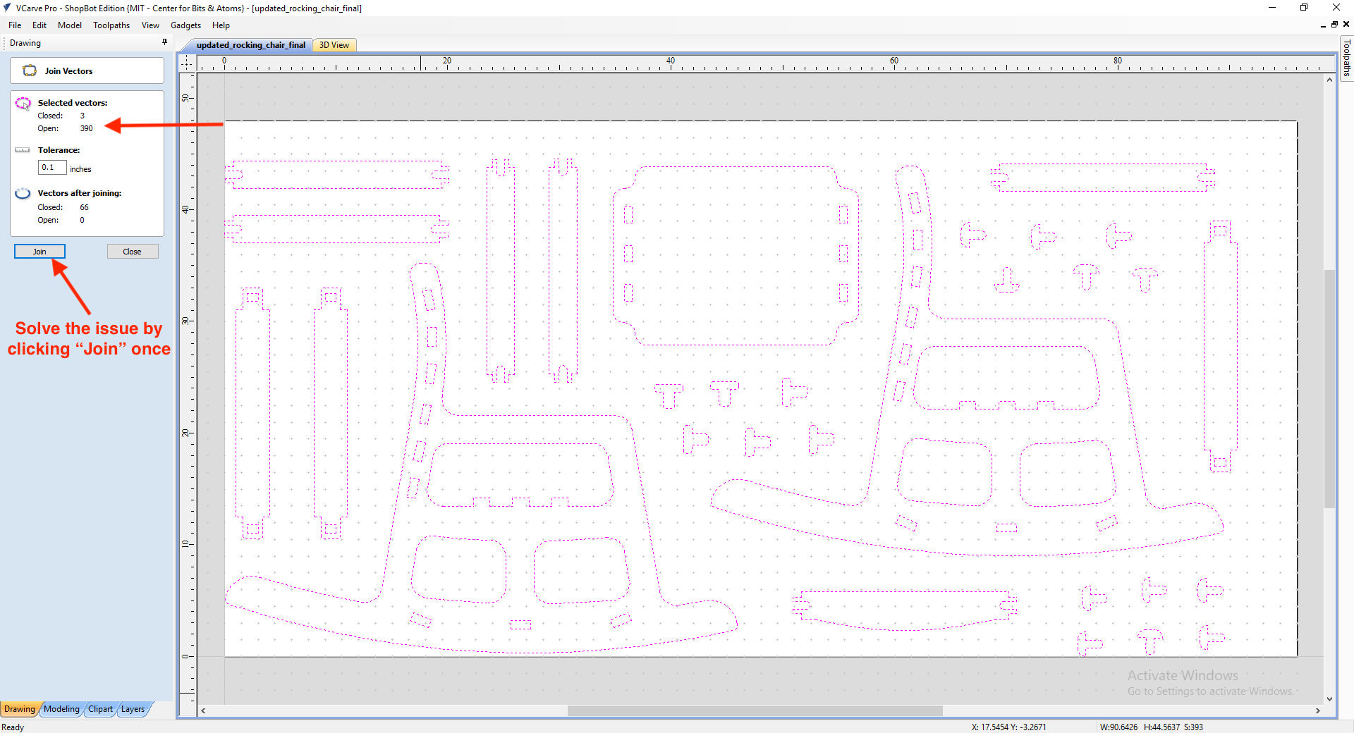
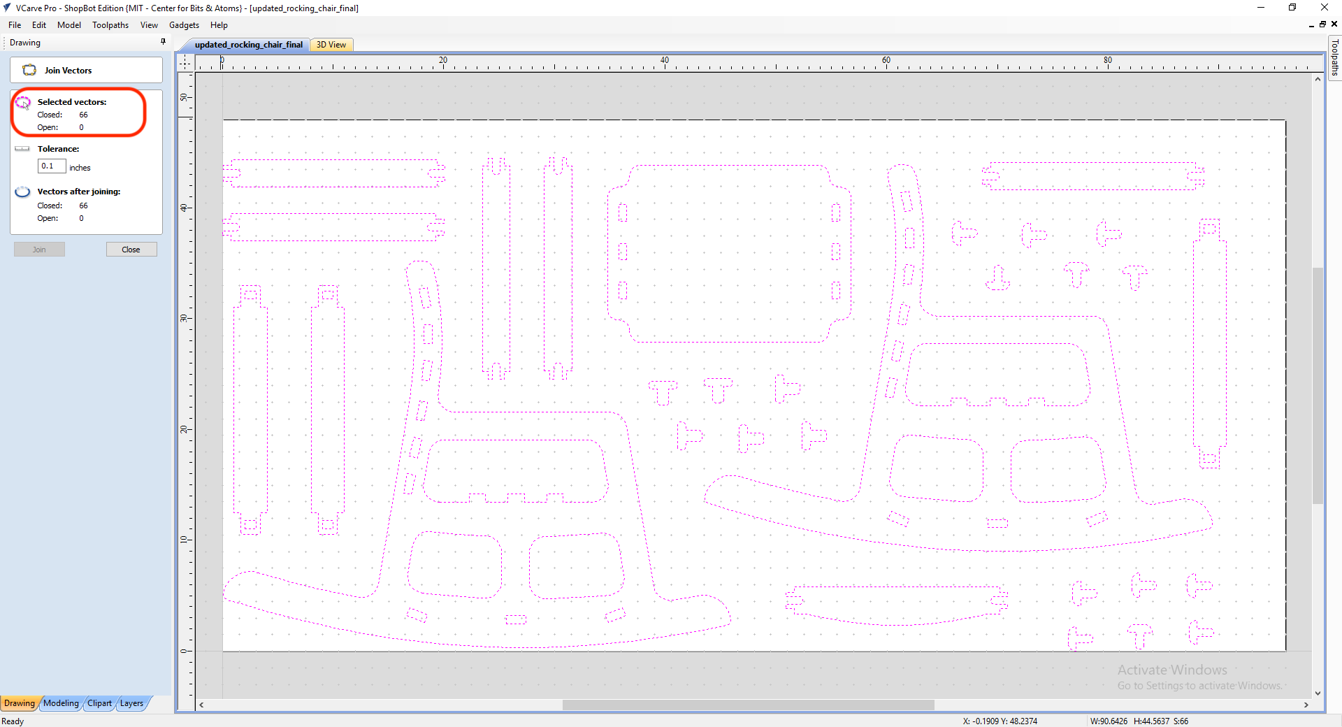
Drawing Screen:
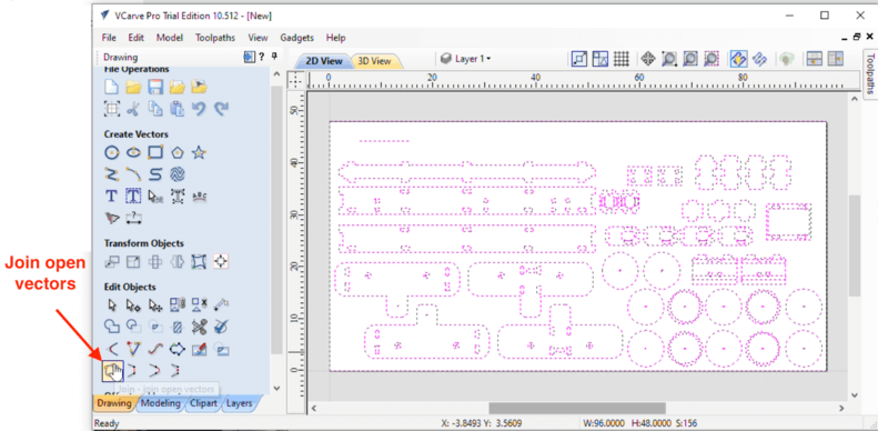
After setting the job size and choosing the XY datum point, the next step would be to make sure there was no open vectors with the Join open vectors tool. ShopBot does not machine open vectors so if there are open vectors in our parepared .dxf files, we just need to click this tool to double check, and it will fix for us with one click.
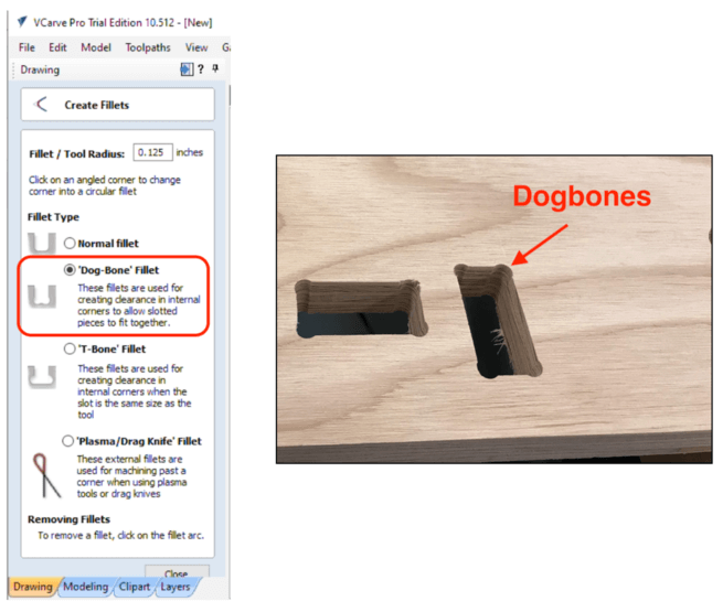
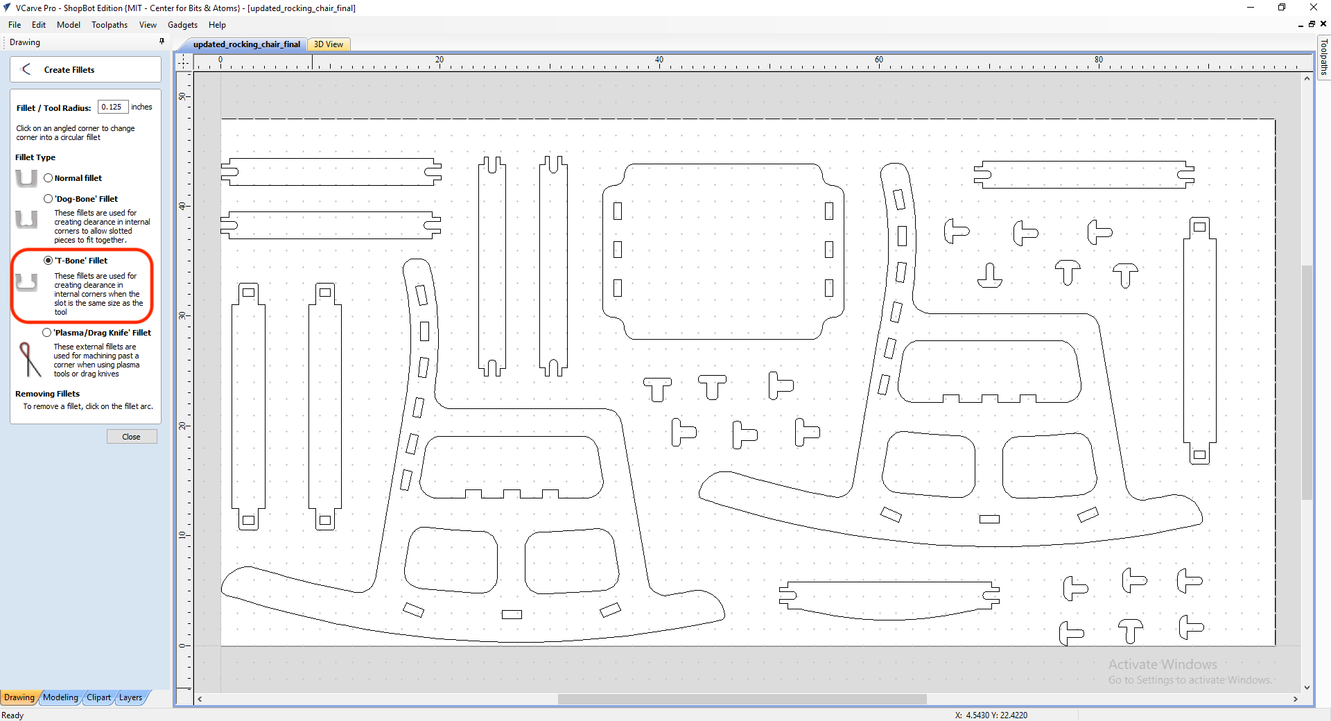
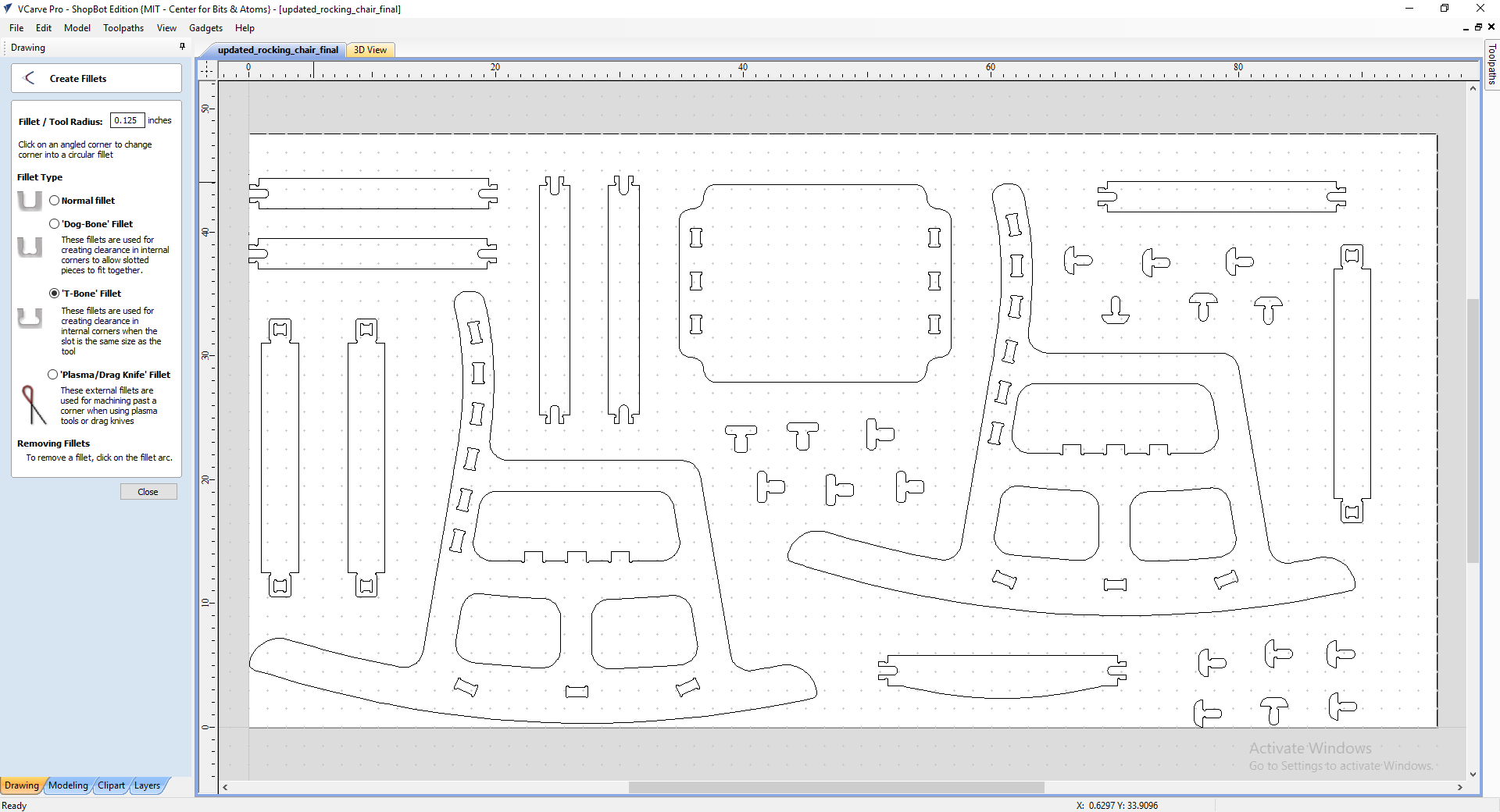
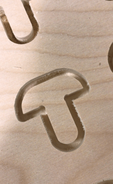
As CNC wouldn't be able to mill sharp corners, we also need to add fillets, one suggested fillet was the dogbones, which shapes like dogbones, as its name implies.
Toolpaths Screen:
Different materials require different end mills and speeds to be machined. I found this guide with some helpful charts for choosing the right bits and speeds for the job.
Helpful Resource: End mill selection guide
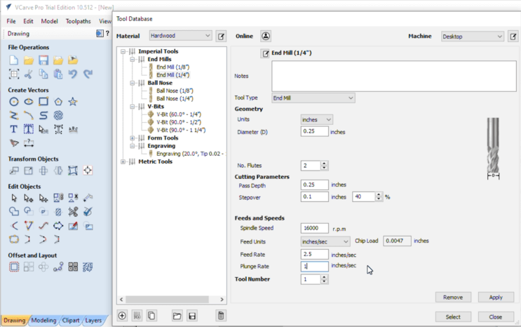
Since I will be using a 1/4" down-cut bit (Bit ID: 57-910) for machining my design, I have recorded the following suggested settings by Spencer:
- Name: 1/4" Down-cut (57-910)
- Diameter: 0.25 inches
- Pass Depth: 0.25 inches (pass depth = tool diameter)
- Stepover: 0.1 inches 40% (As suggested by Neil in the Global Lecture, we use stepover to achieve a more clean finish. Stepover ~= tool diameter / 2)
- Spindle Speed: 16000 r.p.m
- Feed Rate: 2.5 inches/sec
- Plunge Rate: 1 inch/sec
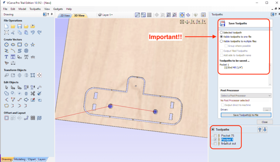
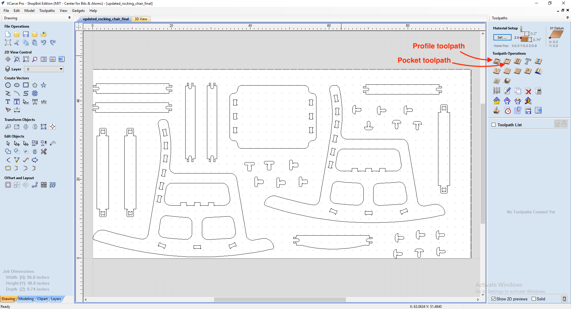
We also need to add tabs to make sure the workpiece does not move around towards the end of the job. However, we were told to avoid putting tabs in the corners as the corners were the strongest spots on a material, and that would be difficulat to clean up. We were also adviced not to put too many tabs. After that we can preview the toolpaths. It is highly recommended that we review the simulations to make sure things are as expected. Next, we save the toolpaths by clicking Save Toolpath in the Toolpaths screen. One important thing to note is that we must only check and select the box of a single job each time we save a file, otherwise it would save all toolpaths in one job. The toolpaths are saved in .sbp format (G-code files).
Highlighted = selected; checkbox = visible; use visible toolpaths for one file. Also make sure to create a separate toolpath file for each toolpath.
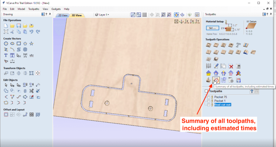
We were also suggested to use the Summary of all toolpaths, including estimated times tool to double check to make sure the toolpaths were correct, if the estimated time was too short or too long, then probably there was error in the unit system.
Setting up the ShopBot
Initial Preparation:
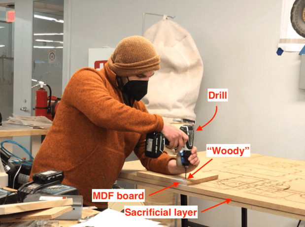
Similar to PCB milling, we need to use a sacrifical layer to make sure the mill doesn't cut through the machine bed. Next, we also make sure the wood that we are actually using (in this case, the MDF board) is fixed to the sacrifical layer. In 3DExperience Lab, we use the power drill to drill down the "woody" on four corners of the board so that the wood is pushed down to the sacrificial layer / machine bed.
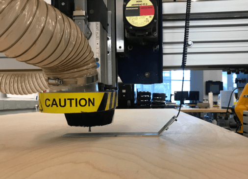
Changing Bits:
Before changing the bit, we want to move the milling head in front. Spencer used the keypad to manually move the X and Y axis to achieve this.
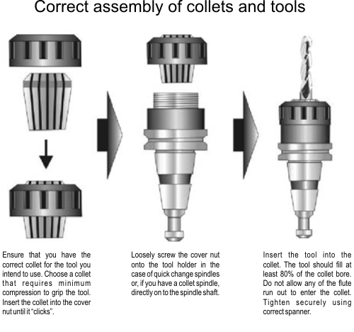
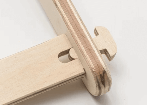
After moving the milling head to the front and making sure the machine was off, we could change the router bit. Spencer showed us to remove the old bit by using two wrenches, one goes on the shaft of the router, and the other goes on the locking nut (tool holder for the bit). The following image shows the correct assembly for changing the router bit. Once the new bit is installed to the toolholder, we want to pull the bit up 1/8" inch, doing so allows the collet to tighten around the bit.
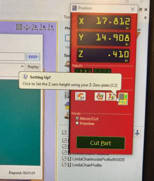
Zeroing the machine:
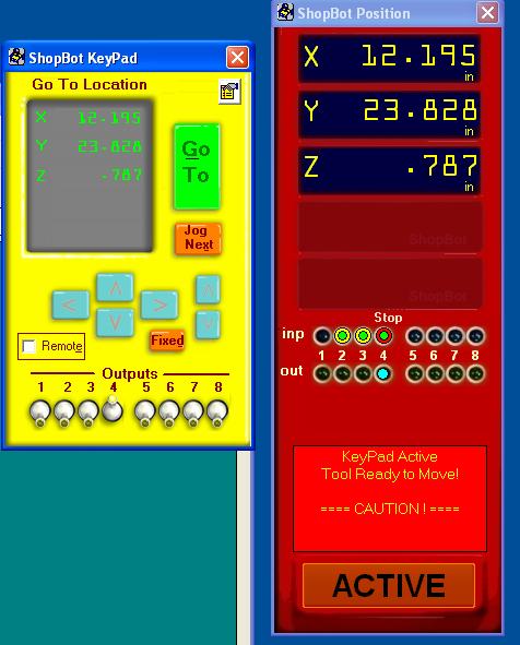
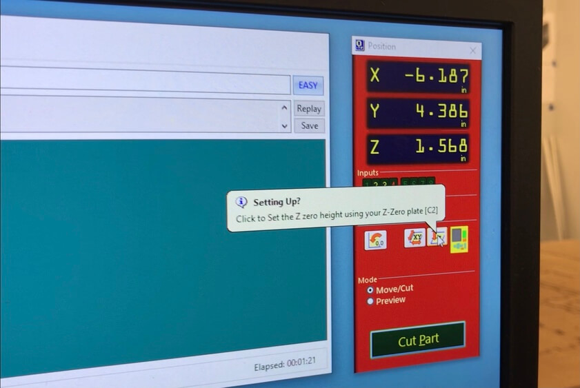
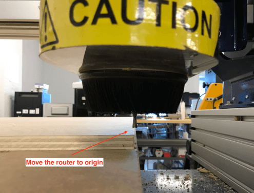
Next, we need to align the z-axis of the milling machine to the wood. To do so, we need to move the spindle chuck more towards the center of the wood. Spencer showed us how to use a metal plate to automate the z-aligning process. First, he tested the plate by tabbing it to the router bit. The moment the metal plate tabbed the bit, the light on the Input 1 as well a ACTIVE would be on. That was a good sign because it means that we were ready to automate the z-alighning process. First, Spencer placed the metal plate on the wood but near where the router bit would hit.
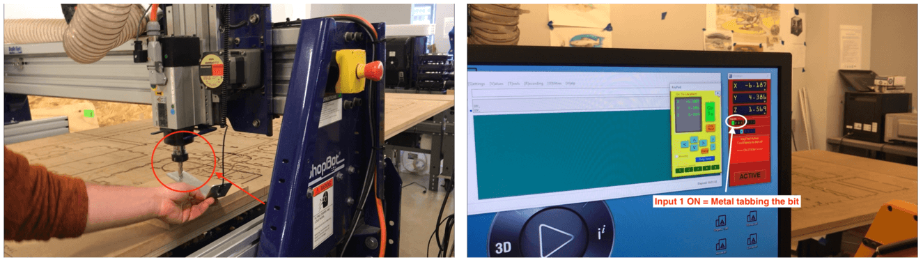
He then pressed the Z button on the red keypad once. After that, we saw the router bit tabbed the metal plate twice slowly, and that completed teh z-aligning process.
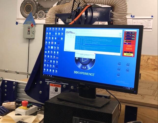
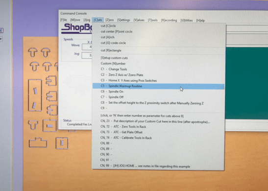
As the machine operates, we see the different lines of G-codes processing on the green ShopBot window.
Group Assignment
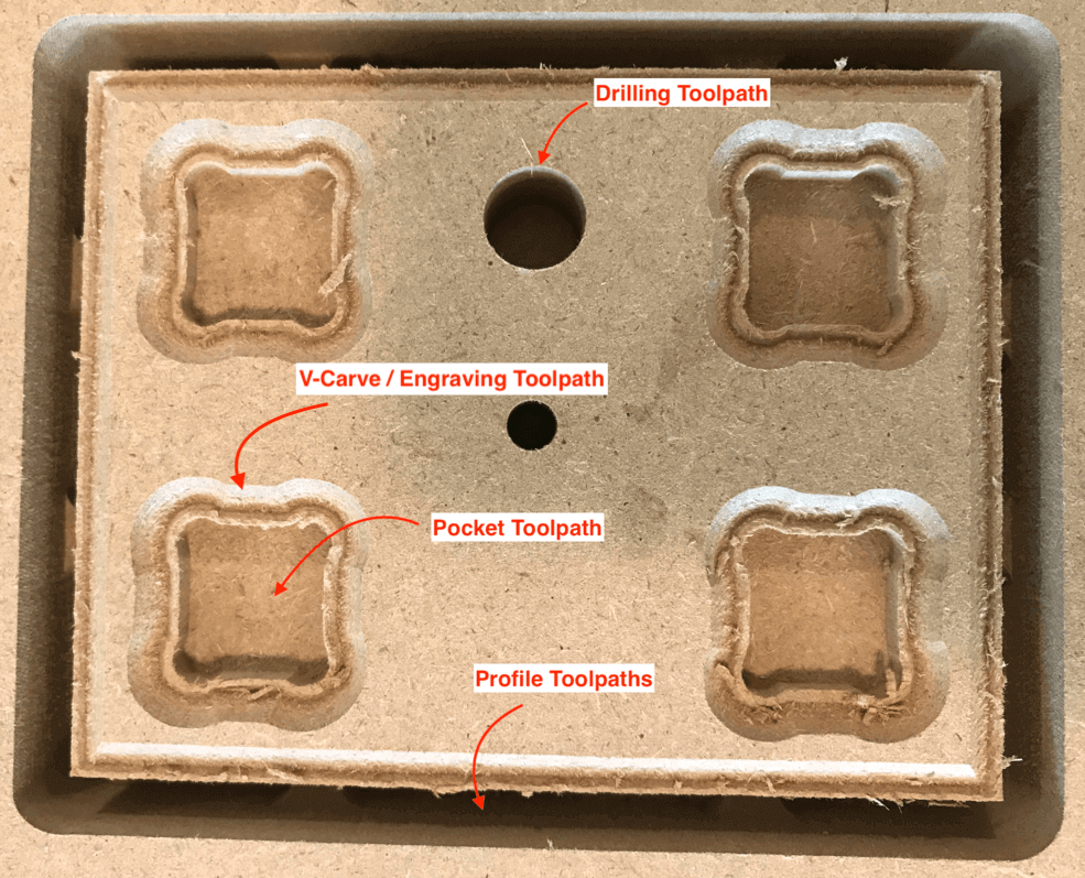
We had the chance to run some test cuts on the machine and work on the group assignment for this week. During the demonstration section, Spencer has saved the toolpaths for the test cut, so in our actual practice, we each were able to experience changing a router bit and running a toolpath. Spencer also showed us how to use a pencil to do a marking pass on the wood, this will be so helpful before making the big cut!

The toolpaths that we ran were: drilling toolpath (x 2, using a drilling bit), V -carve / engraving toolpath (x 1, using a v-bit), pocket toolpath (x 1, using a 1/4" down-cut bit), and profile toolpath (x 1, using the down-cut bit). I learned that we should run the toolpaths from inside to out, so the order in here would start with drilling, then engraving, next pocket, and in the end, profile cutting. When machining the vector, we also made sure to double check inside vs. outside cuts, i.e. pockets were inside cuts, and profile were outside cuts.
Helpful Resource: Drill / End Mills: Drill Style vs. Mill Style
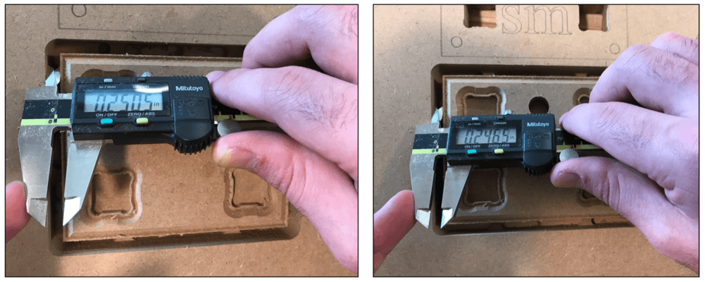
We tested the runout using the square that were cut as the outside profile. The tool that we used was the 1/4" down-cut bit, however, we found that the cut dimension was varied in different spots, so we knew that the cut was not aligning properly, and we thought that probably it was due to the MDF material being soft. We eneded up using the average of the cut (0.2495") to calculate the runout, which was:
runout = (actual cut - tooldiameter) / 2 = (0.2495 - 0.25) /2 = -0.00025"
Individual Assignment
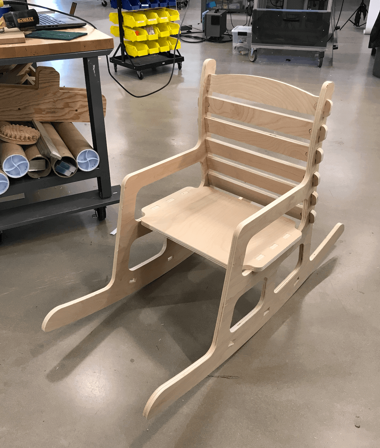
Designing a Rocking Chair
For my individual assignment (make something "big"), I have decided to design and build a rocking chair. I got this inspiration because my parents enjoy looking at their vegetables at the backyard, so I think it would be a nice furniture to add to our home. As this was my first large project with interlocking parts, I had the opporutnity to explore and experiment with different joints, thanks to the guidance of my instructors Spencer, Greg, and Luciano.
Rocking Chair - Version 1
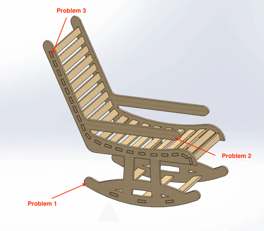
Once again, I used SOLIDWORKS for my CAD. This is my first design, it has a inclied back and also has a contoured seat. However, this design presented a few problems:
- Problem 1: (from Greg) the rocker was not long enough to support the inclined back, and this would make the user fall back easily.
- Problem 2: (from Luciano) there was no support for the armrest, so it would become a fatigue spot when putting pressure on it.
- Problem 3: (from me) the pockets on the chair side can also weaknen the chair life.
Rocking Chair - Version 2
So I decided to sketch my rocking chair again from scratch. This time, I set up a parametric table and a "chair wireframe" when designing the pieces for my rocking chair. I decided to reduce the inclination angle but still kept it within the ergonomics range, which was 10°.
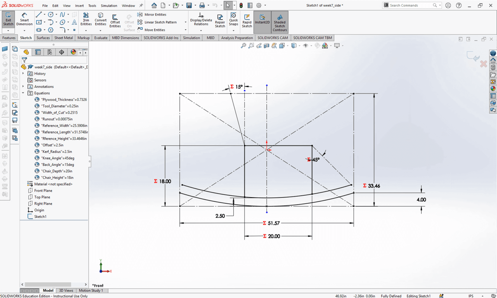
Initially, I set my chair 53" from edge to edge, however, as I worked on the design, I recalled that we needed to fit all files into one 96" x 48" plywood, so I trimed the rocker to be 46" long.
I also paid more attention to the joints, in this case, I decided to add some T- joints to secure the base of my chair.
Here is how my chair looked:
And here is the 3D view of the model in SketchFab:
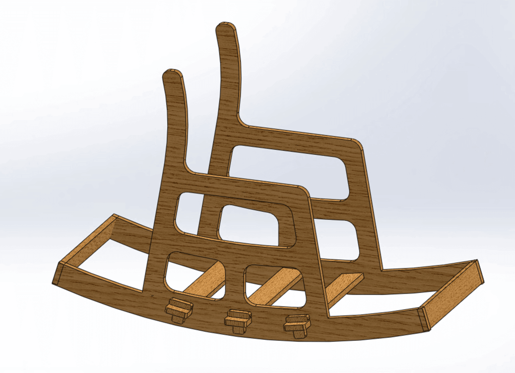
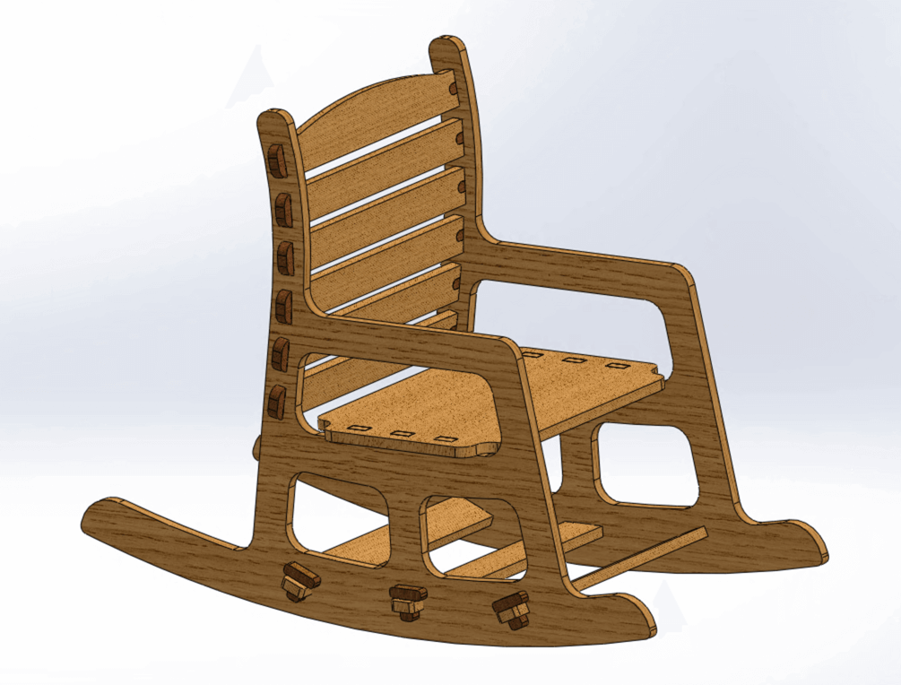
Rocking Chair - Final Version
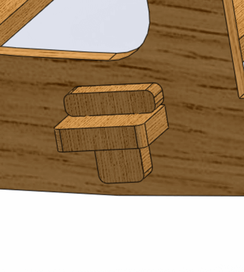
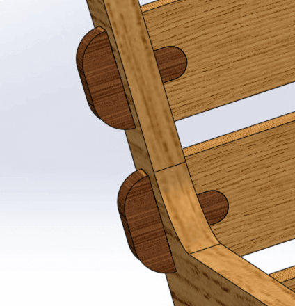
I was happy with the second design, however I also felt that there was room for improvement. So I sent my design files to our instructor Spencer for review, and he gaved me a great suggestion to add the wedged mortise joints (I have been calling them "key joints" 😆) to secure the back bars and the side of my chair.
I really liked the minimalist style of this joint and so I adopted this idea. The shape of the joint was like also a T, but it would be a different style of T, so that has added some interesting feature to my design.
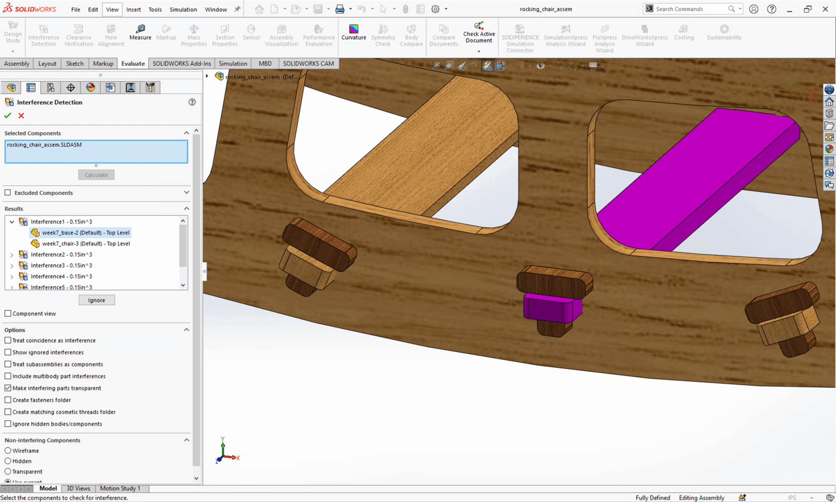
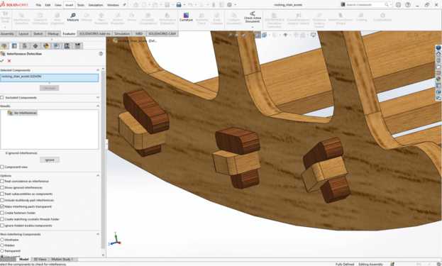
Before exporting the files to .dxf format, I also used some handy tools in SOLIDWORKS to check for mistakes. Here, I was using the Interference Detection tool.
I set the material as maple, and used the check mass tool to have a sense of how much the chair would weigh. The tool showed that the machine would weigh about 25 lbs, so that means I would still be able to carry it 😎.
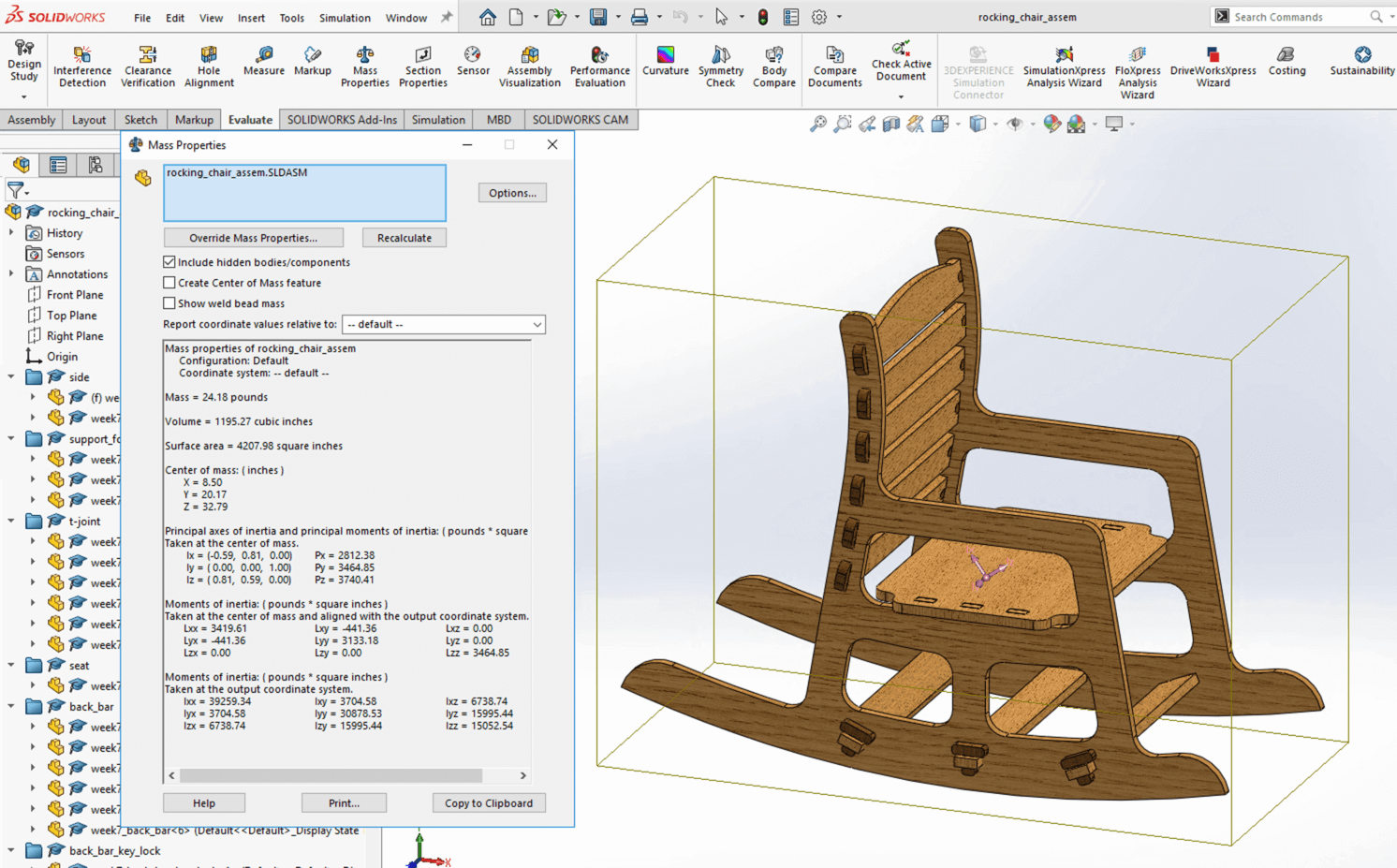
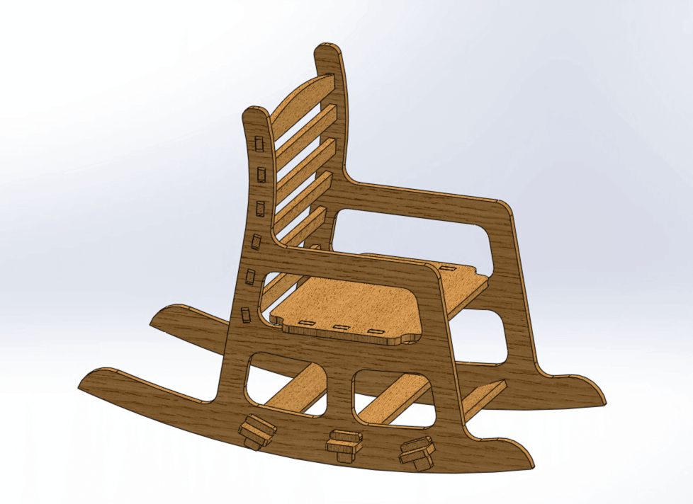
Here is the final design of my rocking chair:
And here is the 3D view of my final design for the rocking chair in SketchFab:
Preparing DXF File and Scaled File
When I was satisfied with the final design, I exported each part as a .dxf file and assembled them in a sheet of 96 " x 48 " in Adobe Illustrator. I used the rotate and reflect tool to nest my design to make use of the material wisely. I also made sure there was enough clearance in between the parts (1 1/2") to add tabs in the CAM process.
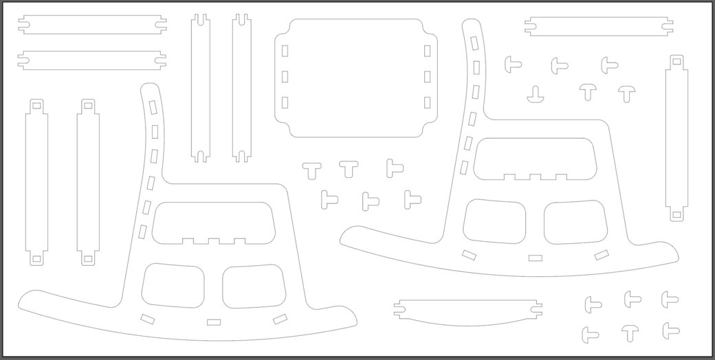
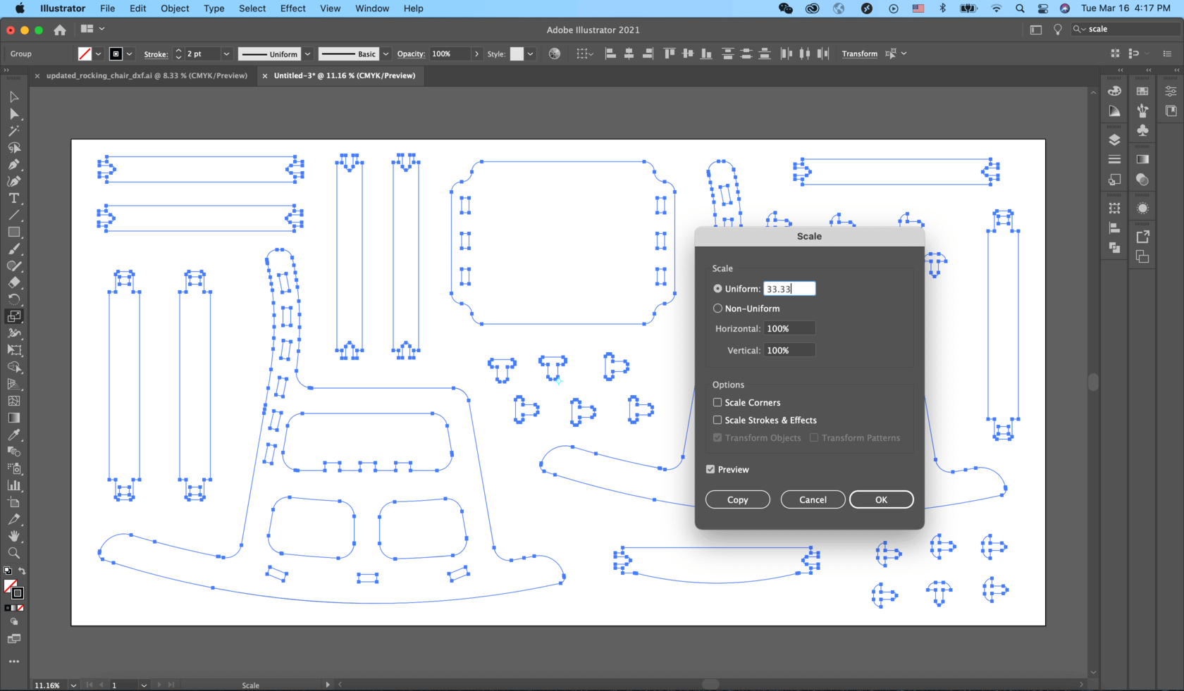
I also prepared a scaled file (33.33% of the original size) in Adobe Illustrator for prototyping with a 6mm cardboard using the laser cutter.
We initially planned to machine our designs on Monday. Due to safety reason and limited staff at the lab, our instructors advised us to postpone using the ShopBot until one of the instructors presented, which would be next Monday. I look forward to making my first big design!
Creating Toolpaths and Setting Up the Machine


.PNG)
.PNG)
Here is a short video showng the preview of toolpaths in VCarve. This feature was very helpful!
Machining and Final Result
Here is a short video showing ShopBot working:
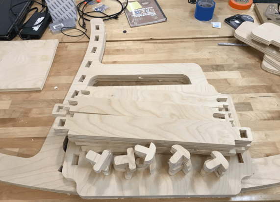
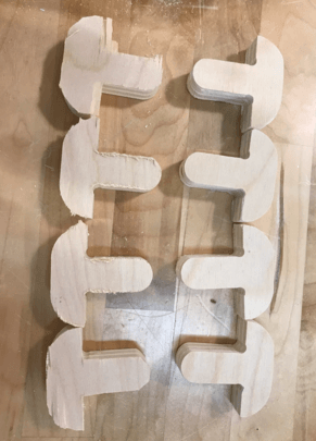
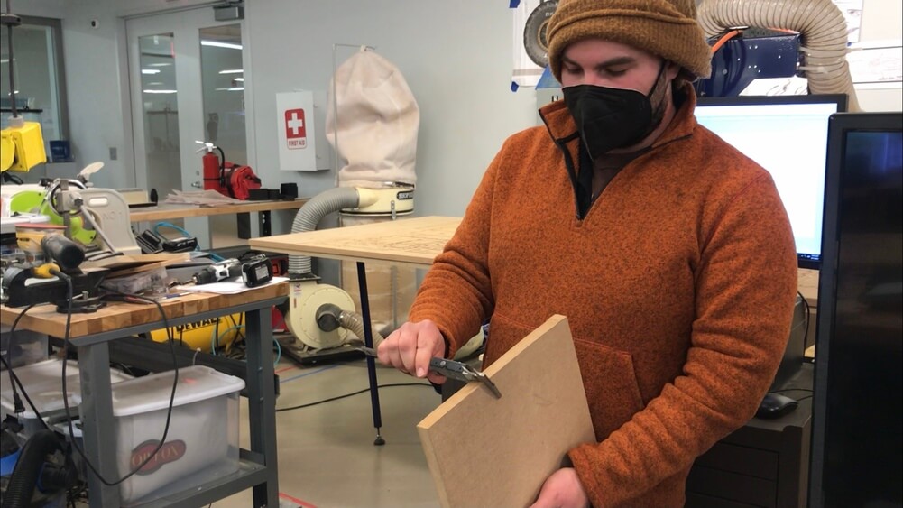
While assembling the chair, I noticed that the pockets for the bottom supports got smaller in the actual chair, and as a result, they didn't fit well. Although sanding down the suppor helped with the fit, the strength also got reduced, so I decided to redesign my bottom supports and do another cut for them.
Files
Please find below the files that I made for this assignment.
- Rocking Chair
- Initial Designs (Version 1, Version 2) - SOLIDWORKS 2020 and STL models
- Final Design - SOLIDWORKS 2020 and STL models
- DXF File (Without Dogbones) - Prepared in Adobe Illustrator
- DXF File (With T-bones) - Prepared in VCarve Pro
- Other vector file format (With T-bones) - .svg, .ai
- Scaled Vector File (.ai, .svg) - for prototyping in laser cutter (without T-bones)
- Scaled Vector File (.ai, .svg) - for prototyping in laser cutter (with T-bones)