
This work is licensed under a Creative Commons Attribution-NonCommercial-ShareAlike 4.0 International License
Week 13: Output Devices
Apr 25, 2021Summary
This week's assignments
- Group assignment:
- Measure the power consumption of an output device and document how you determined power consumption of an output device with your group
- Document your work (in a group or individually)
- Individual assignment:
- Add an output device to a microcontroller board you've designed and program it to do something:
- Document what you learned from interfacing output device(s) to microcontroller and controlling the device(s) ✔
- Describe your design and fabrication process or linked to previous examples ✔
- Explain the programming process/es you used ✔
- Outline problems and how you fixed them ✔
- Include original design files and code ✔
- Include a ‘hero shot/video’ of your board ✔
Resources Used
- Software: KiCad, Adobe Illustrator, Arduino IDE
- Hardware: Trotec Speedy 400 Flexx
Skills Gained
- Vibration Motor Usage, Debugging
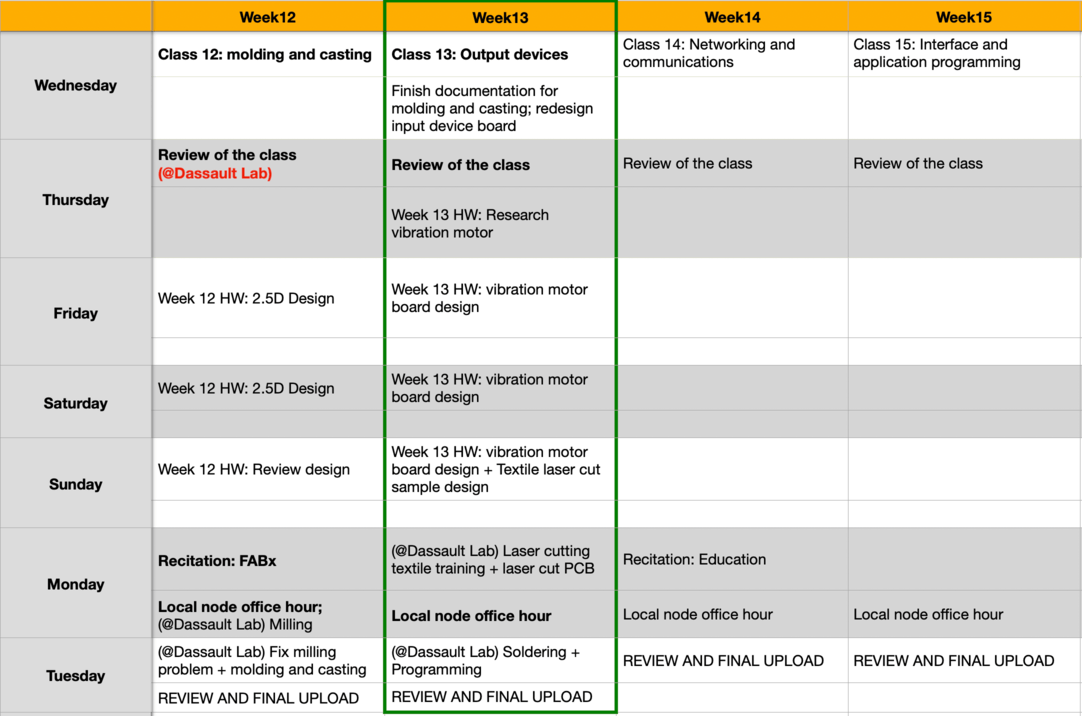
My Weekly Schedule
Output Devices for My Final Project
Apr 24, 2021Research: Components for a Vibration Motor Drive Circuit
For my final project, I was planning to use a vibration motor as my output device, so I started by doing some research. According to this tutorial by Precision micro Drives, the output signals from digital microchips and microprocessor ports are designed to drive no more than 5~15mA. Since all vibration motors consume more current than this, a driver circuit is required to control the flow of power to these motors. The most popular method to drive small vibration motors is to use a cheap enhancement-type (the most commonly available type) MOSFET.
Research: MOSFET
Following this tutorial, I made a vibration motor driver circuit in TinkerCad with Arduino UNO.
The tutorial showed how to use a BJT Transistor to drive a motor, which according to this website, "... they are less efficient and require heat-sinking when high currents pass through them. Heat-sinking would also be required if one were to use a MOSFET in its linear region as well, but due to the high inefficiencies, it is unlikely that any applications would use this approach."
Another way to drive the motor is by using MOSFET as a voltage regulator. In our lab, we have P-channel MOSFET and N-channel MOSFET, here is what I learned from the tutorial regarding the difference:
High-side – i.e. a P-channel MOSFET is used and the drive signal is active-low. This is required for 1.5V power supplies because N-channel MOSFETs tend to have a prohibitively high threshold voltage (Vgs).
Low-side – i.e. an N-channel MOSFET is used, and the drive signal is active-high. N-channel MOSFETs generally have a lower on-resistance and therefore where there is enough drive voltage to be sure of putting the MOSFET in the saturated region it will be more efficient. Plus, N-channels are generally cheaper! (source)
Here is a reference image for creating a vibration motor circuit driver:
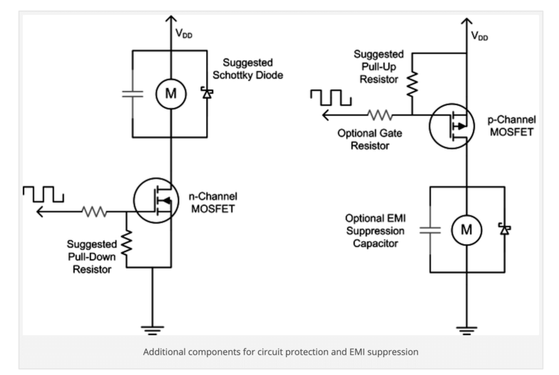
I planned to use the n-channel MOSFET as my voltage regulator. As shown in the image, when creating the Vibration Motor board, I would also need to include a Gate Resistor, a Pull-down resistor as well as the Schottky Diode.
Research: ERM and LRA Motors
According to this SparkFun tutorial, the difference between the two motors is how the movement of a mass is displaced. LRA vibration motors require an AC signal, driving a sine waveform that is modulated to get multiple effects. ERM vibration motors use a DC motor with a counter weight attached. The DC voltage controls the speed of the motor.
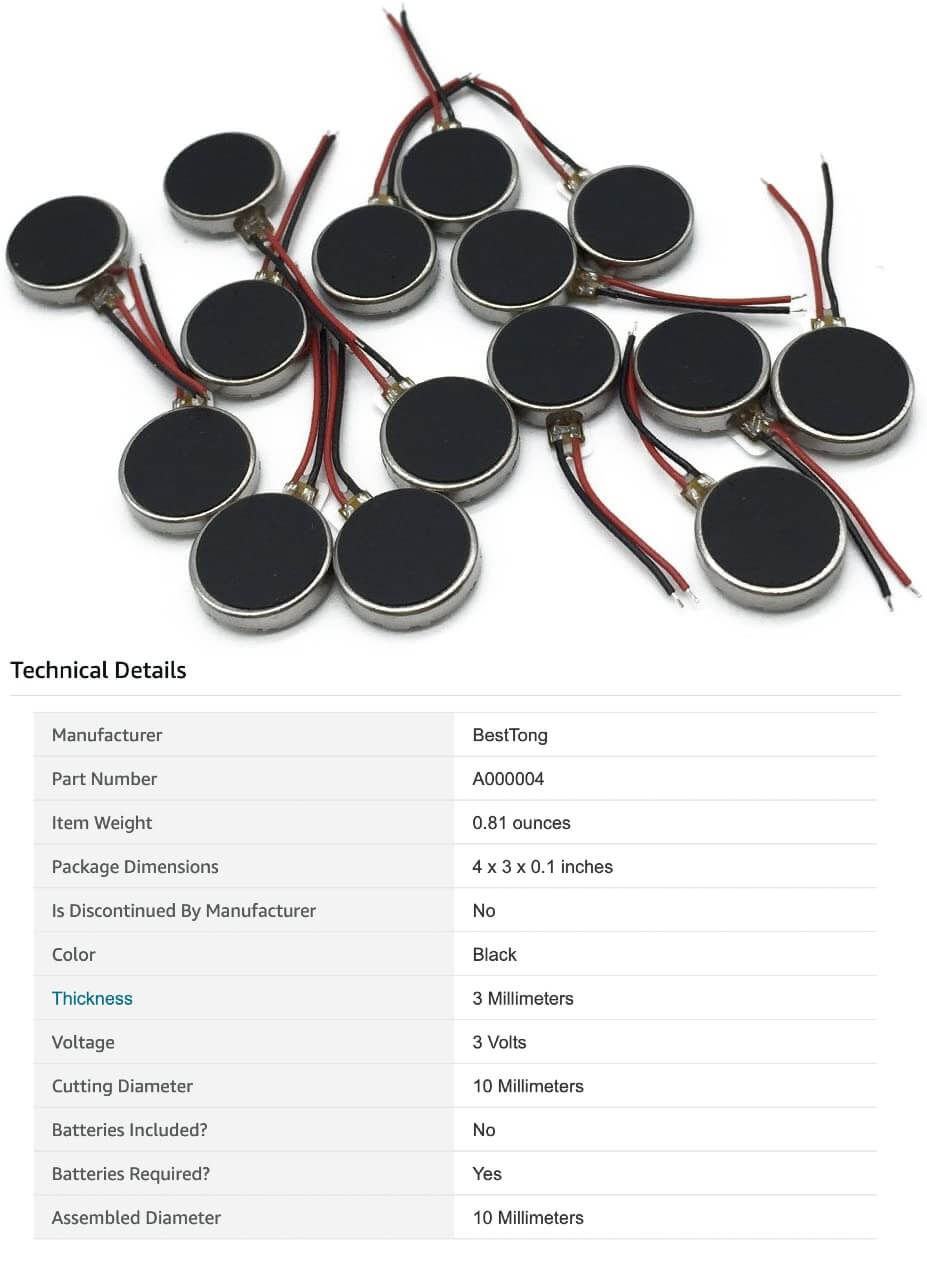
After doing some research on Fab Academy Archive, I decided to use these coin button type motors for my final project.
PCB Design
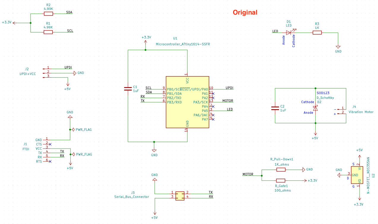
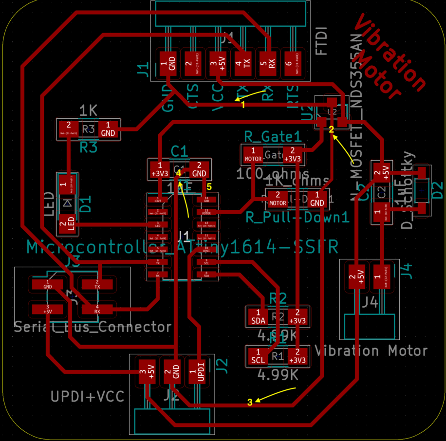
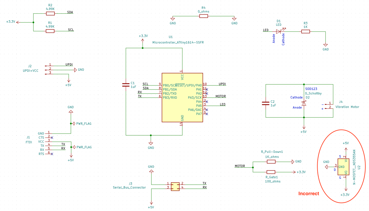
Apr 26, 2021Here is the schematic for my initial vibration motor board. I have included the serial bus to set up for the networking week, I have also included a small gate resistor (100 ohms) and a larger pull-down resistor (1K ohms) for the MOSFET.
However, when I connected the components, notice that I had to bypass the UPDI+VCC adaptor to get to the GND pin of the capacitor for the microcontroller.
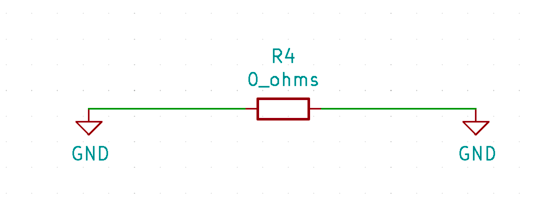
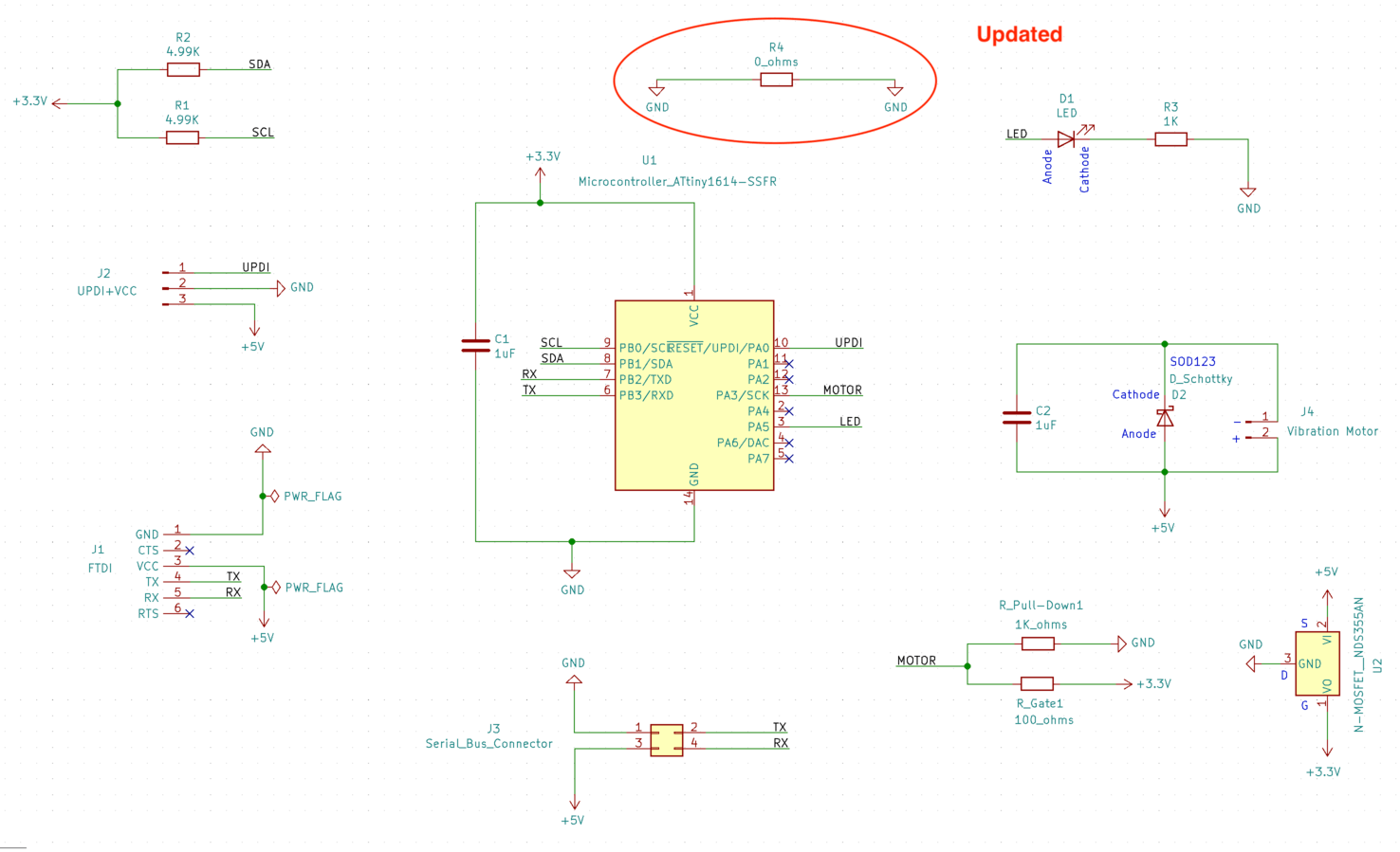
I was concerned about shorting my circuit because I was doing a similar thing for my first input device board, so I consulted my instructor Spencer, and he suggested me to use a 0 ohm resistor to "bridge" the two GND traces. In this case, I updated my schematic to add the 0 ohm resistor:
And the new schematic looked like this:
To update the PCB layout, I first removed the GND trace that connected the UPDI+VCC adaptor to the capacitor C1, then I added the 0 ohm resistor as a bridge for the GND traces between the FTDI and the capacitor. I noticed that there was an airwire shown on my 0 ohm resistor still, and when I ran the electronic rules check, I received the following error
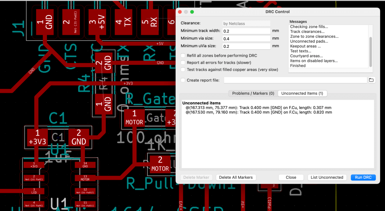
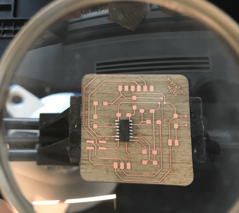
I consulted Spencer again and he told me that it was fine to leave the air wire disconnected. So my final PCB layout is as follows:
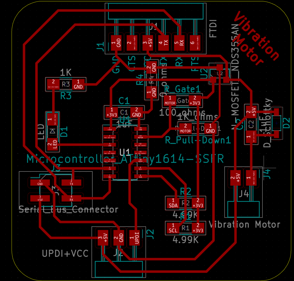
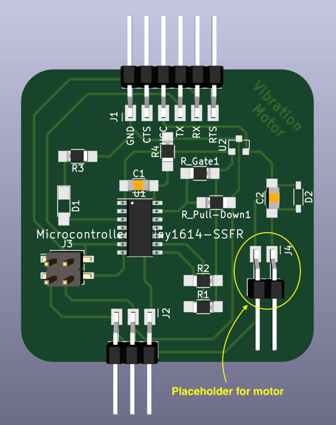
And the 3D view of the PCB is as follows. As shown in the image below, I was usinng the 1x2 header connector as a placeholder for the vibration motor pads.
PCB Production
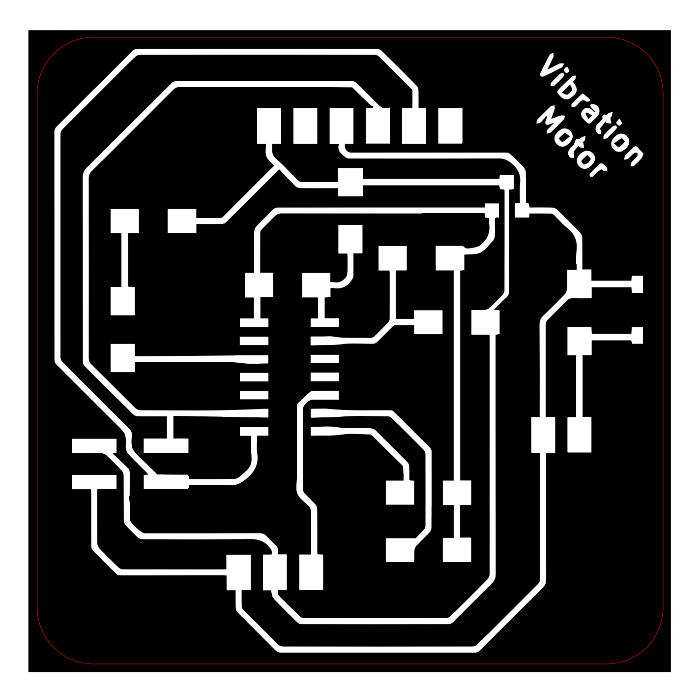
Apr 26, 2021Next, I exported my traces and interior as SVG files, and post-processed them in Adobe Illustrator for laser cutting the FR1 boards. I really like the finish of the laser cut PCBs and I thought it would be a good way for me to get familiar with the workflow before moving onto the flex PCB routine in the coming weeks. Here is the image of the prepared file for laser cutting. The "interior" was replaced by the red frame with 0.001" stroke width. Similar to the traditional laser cutting process, the inner geometries (raster / engraving) would be processed first. The estimated time for engraving was 33 minutes, and the estimated time for cutting the outline was 7 seconds.
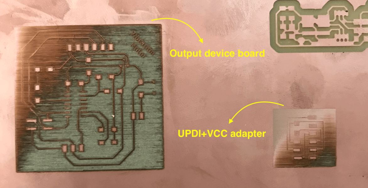
Since I wanted to use the UPDI+VCC adaptor for my board, I also seized the opportunity to laser cut the hello.serial-UPDI.3 board designed by Neil. However, my first attempt was unsuccessful because the FR1 board was not focused well due to warping issue.
Then I replaced with smaller FR1 boards and this time it was a success. Spencer also suggested to use double-sided FR1 boards since they are flatter compared to single-sided FR1 boards. Here is a short-video of the laser cutting PCB process:
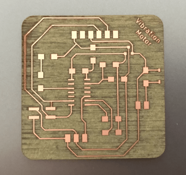
Here is how my laser cut output device board looked:
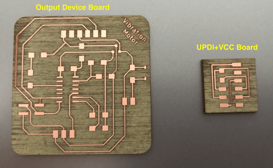
Here is a hero shot of the two boards, before milling:
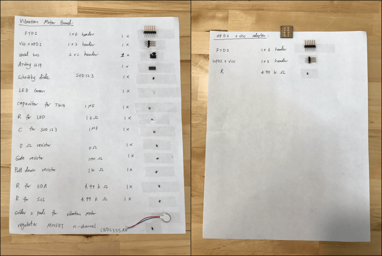
I had collected the components for the two boards, and here is the Bill of Materials (BOM):
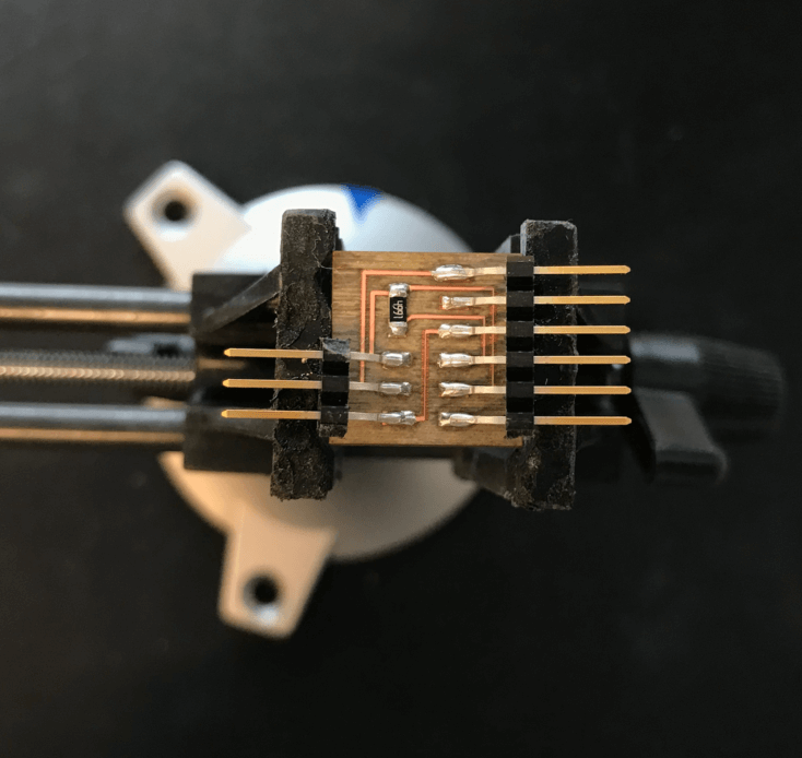
Here is the soldered UPDI+VCC adapter:
Similarly to the previous assignments, I started with soldering the microcontroller ATtiny1614.
I also paid attention to the polarity of the LED, MOSFET, and Schottky Diode. Here is the soldered vibration motor board.
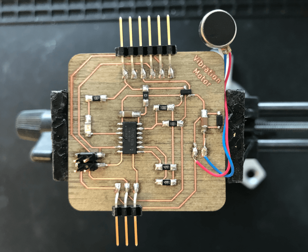
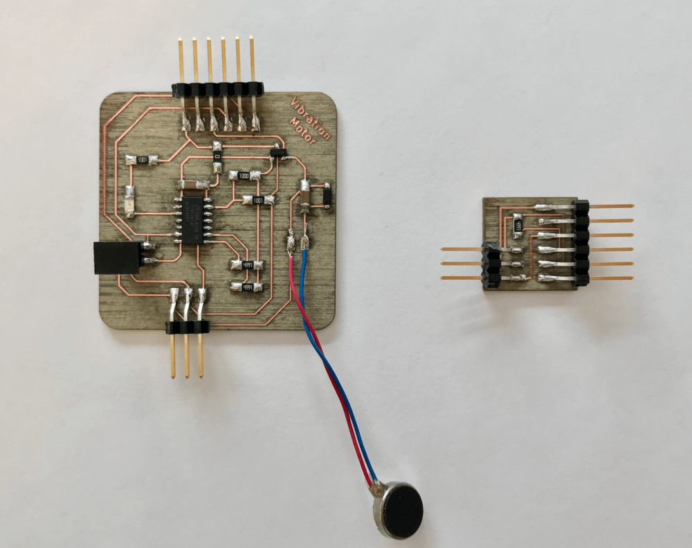
Here is a "hero shot" of the two soldered boards
Programming the Vibration Motor
Apr 27, 2021I used the FTDI USB adapter when connecting to program my board. Here is the set up.
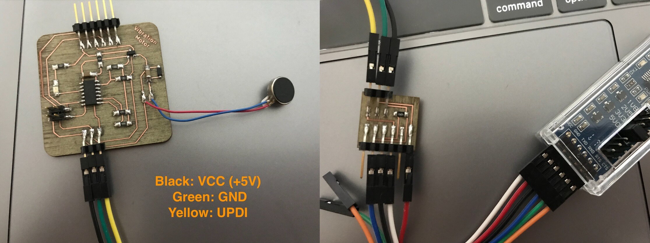
However, when I pluged the FTDI on the USB hub, the light that usually indicates the power turns off, and then the Arduino IDE doesn't detect my board at all. Here is the error message I received in the Arduino IDE.
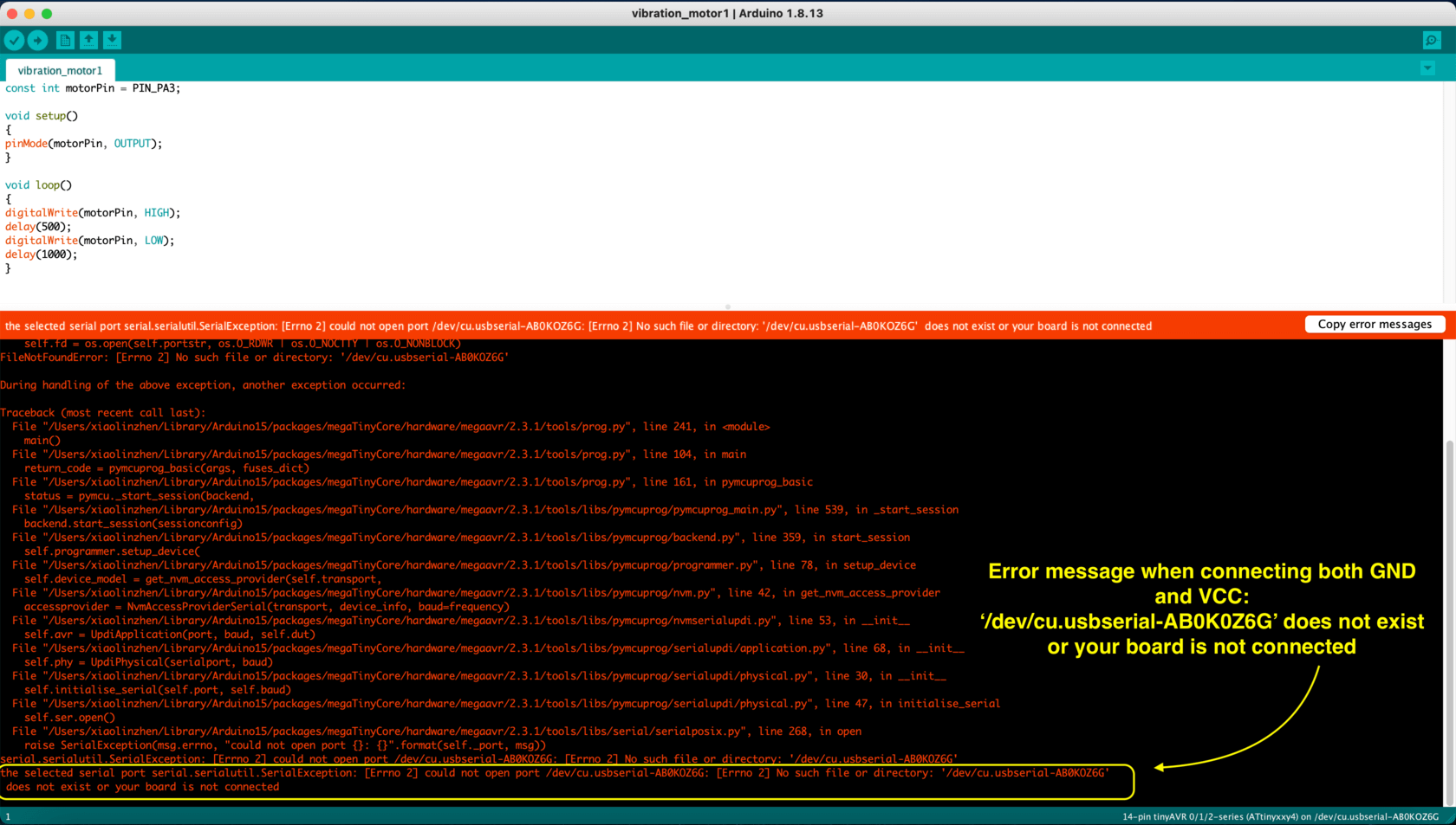
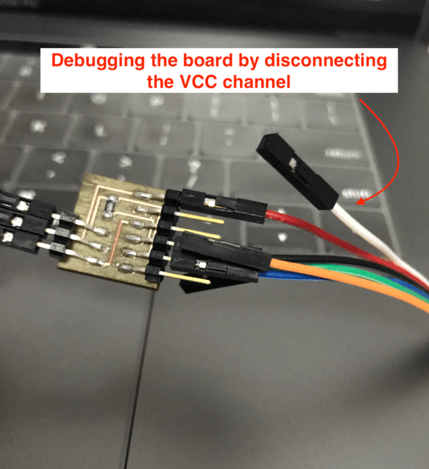
So I started to debug my board. And I noticed that if I removed any of the jumper wires that connected to either the VCC or GND pins, like this:
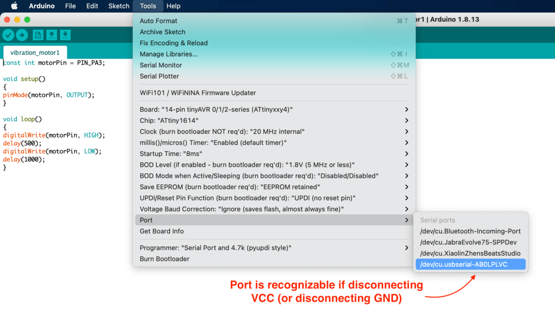
then the LED indicating the power would be back on and the port was recognizable:
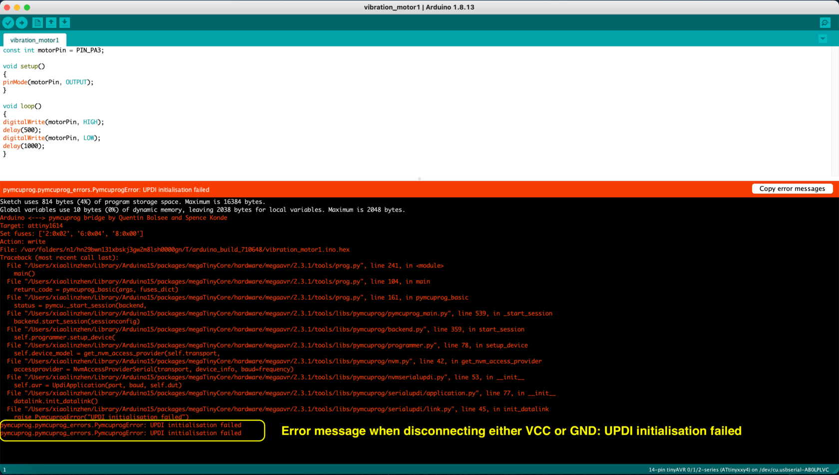
but the Arduino IDE would have this error "pymcuprog.pymcuprog_errors.PymcuprogError: UPDI initialisation failed."
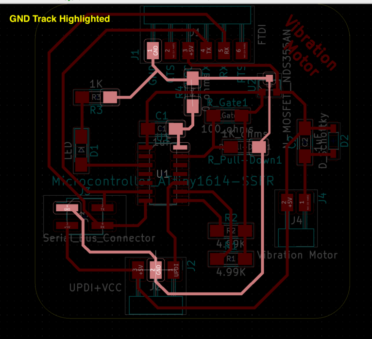
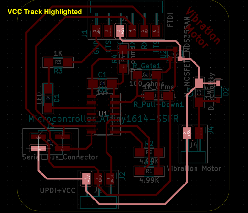
So I started to puzzle if I have shorted my circuit again... I recalled that I received the same error during the Input Devices week, and I thought probably it was because I have bridged the GND pin and the VCC track during reflow soldering stage. However since this error recurred, I decided to examine more carefully what I have done incorrectly. In the PCB layout images below, I have highlighted the GND track the VCC track, to make sure I didn't connect some components (i.e. microcontroller) directly to the GND or power supply... but the result showed that I didn't make this mistake.
Then I started to wonder if I have oriented the LED, Schottky Diode, and MOSFET incorrectly.
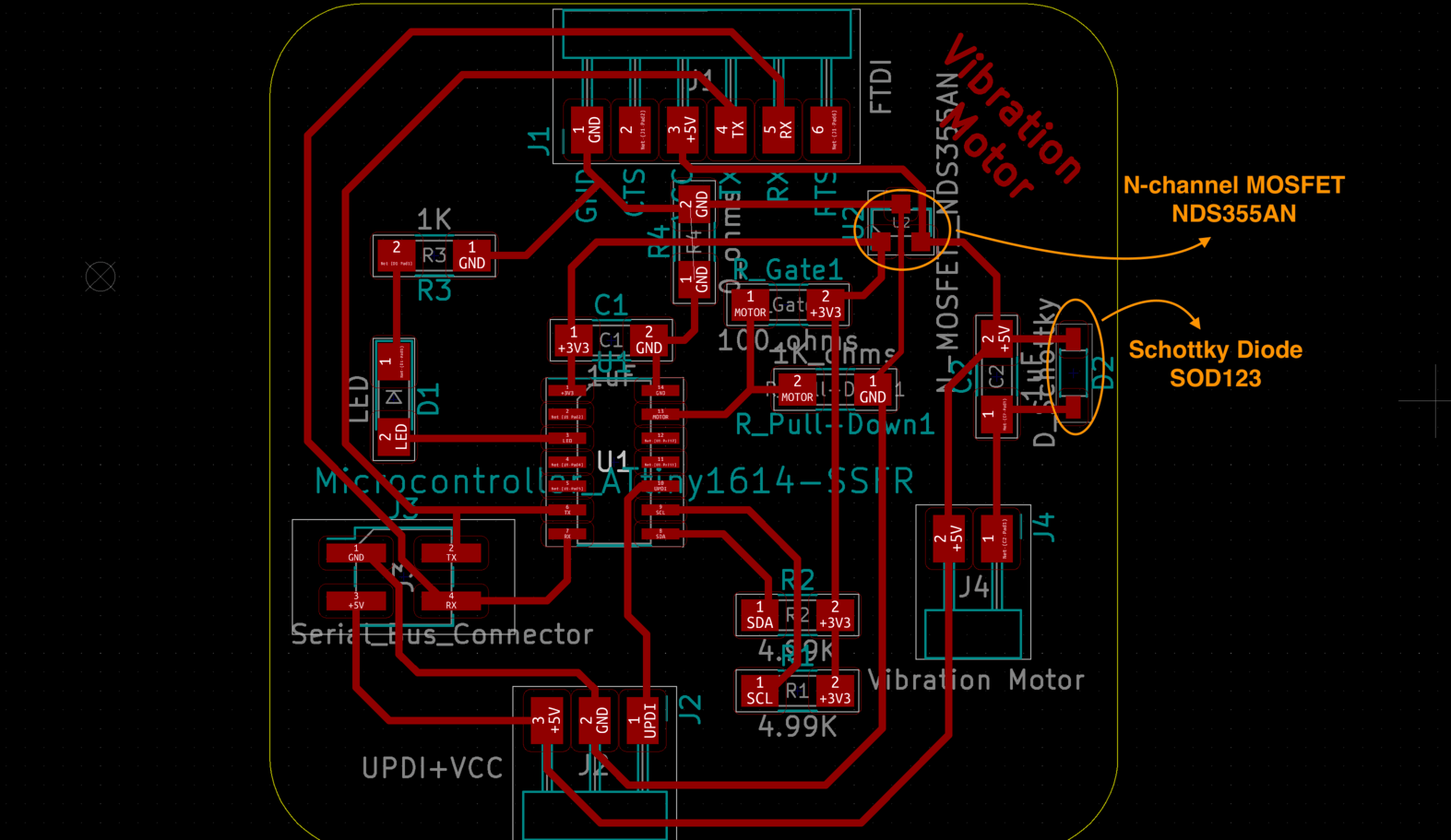
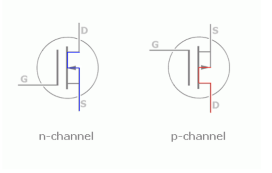
I have checked to make sure the LED and the Schottky Diode was correct, however, I did make a mistake on the MOSFET. The symbols for n-channel and p-channel MOSFET are as followed:
And the n-channel MOSFET that I used is layouted like this:
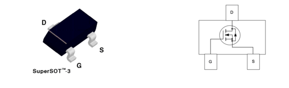
And here is what I had for the schematic, notice the incorrect information that I put on the MOSFET for Gate (G), Drain (D) and Supply (S). After I knew what mistake I had made, my next step would be to correct the orientation of the MOSFET and test again.
May 22, 2021
UPDATE: During Week 14, I upgraded my processer from the tinyAVR-1 series to an ESP32-WROOM for its bluetooth feature. I was also able to put my I/O devices in one board. Please visit my Week 14: Networking and Communication documentation for more information.
Milling and Soldering
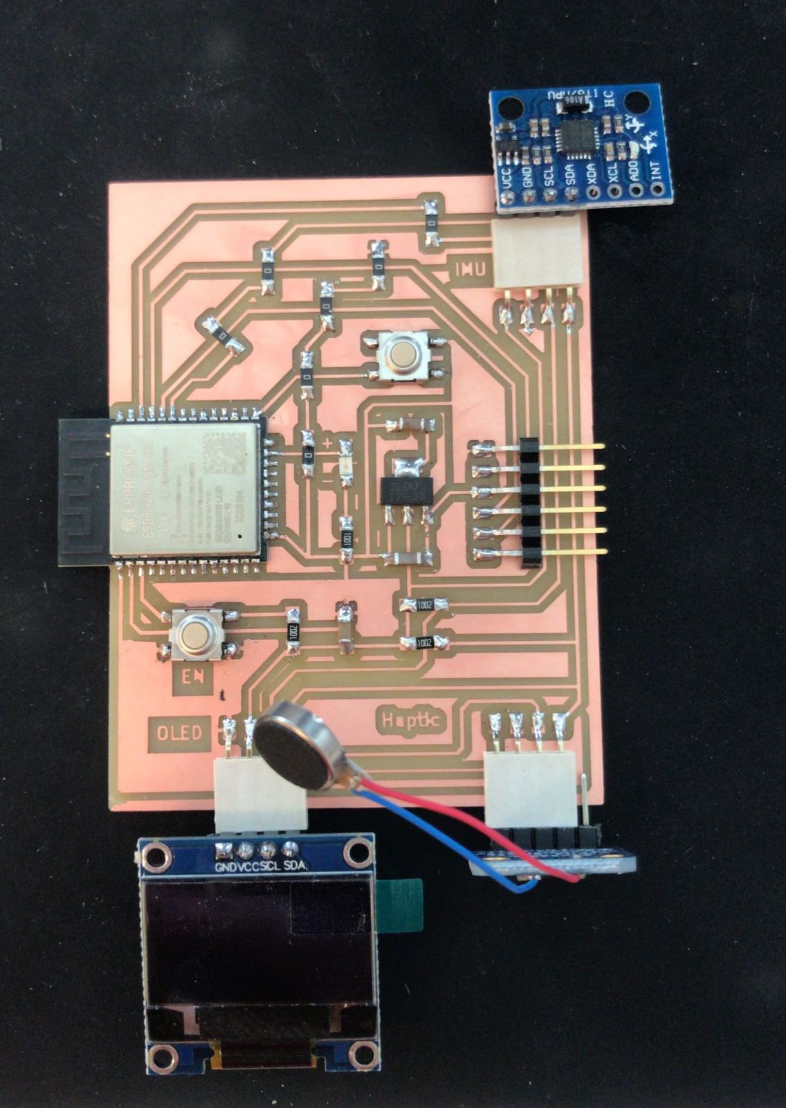
Testing
1) Test the Accelerometer/Gyroscope module and OLED display:
2) Test the Haptic Controller module:
Group Assignment
Jun 19, 2021For the group assignment, we were asked to measure the power consumption of an output device, which is Power = Voltage * Current. For reference, the unit for voltage is volts V, the unit for current is amperes, amps A, and the unit for power is watts W. In this exercise, I would like to measure the power consumption of the vibration motor, via the Desktop Power Supply and via the Multimeter.
Part 1: Using Power Supply
During Week 14, my instructor Spencer taught me how to use the desktop power supply to check which voltage level worked better on the vibration motor. As shown in the video, the voltage is 3.2 V, and the current is 0.07 A, thus P = V * I = 3.2V * 0.07 A = 0.224 W.
Part 2: Using Multimeter
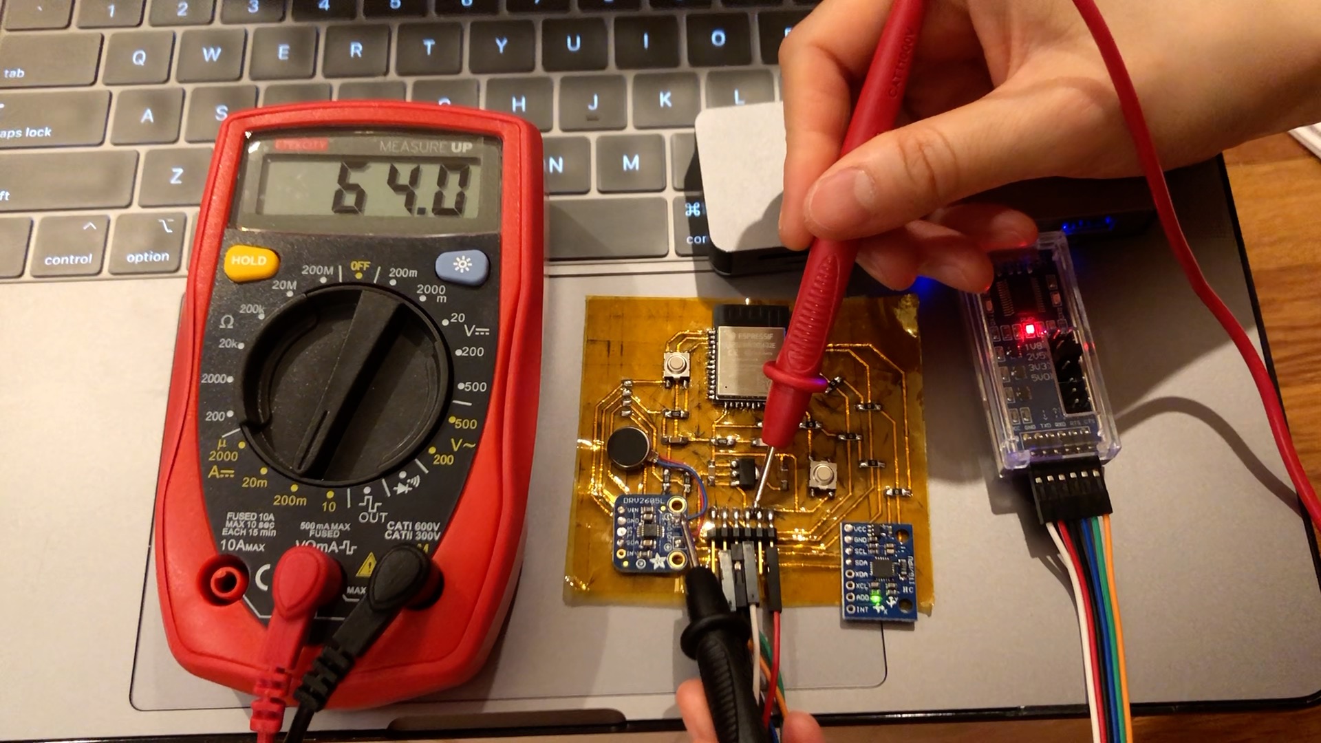
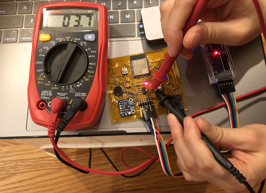
Next, I practiced this exercise on my flexible PCB with a multimeter. In this setup, I used the FTDI programmer as the power source, and I set it to 3.3V. I also turned the multimeter to the 200m channel, this means that the maximum current that can pass through the multimeter should be 200mA.
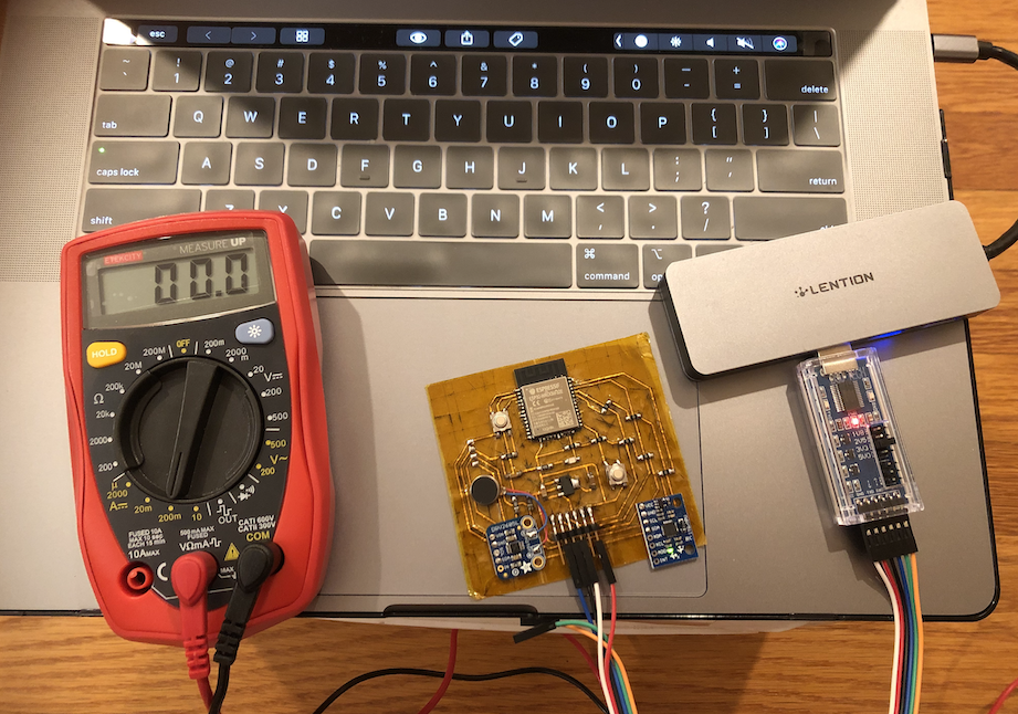
I had connected the GND, VCC, TX, and RX of the FTDI programmer to the GND, VCC, TX, and RX of the FTDI pins on my board. Next, I connected the red wire of the multimeter to the VCC of the FTDI pin, then the black wire to the GND pin (indicate as "-" sign) of the motor. With this connection, the multimeter started to get reading. Here is a short video showing the readings from the multimeter:
The largest reading was 64mA, so the (maximum) power consumption for the vibration motor would be: P = V * I = 3.3V * 0.064A = 0.2112W.
Using the same method, I could also find the power consumption for the LED, which would be: P = V * I = 3.3V * 0.0037A = 0.01221W.
Extra: Laser Cutting Textile
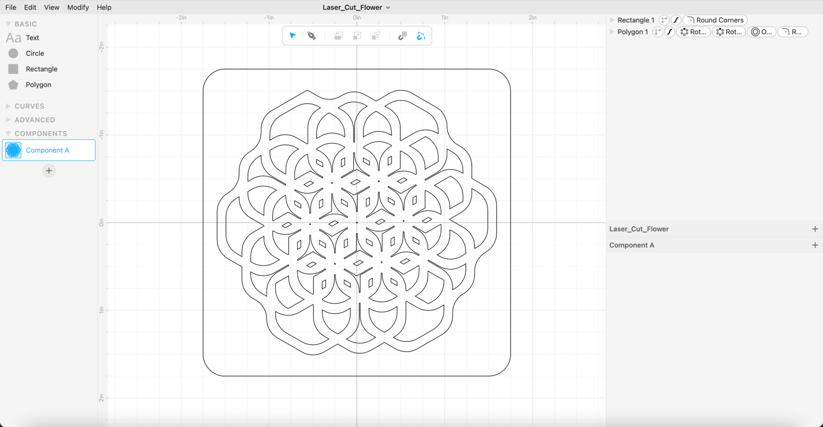
Apr 26, 2021On Monday morning, I received training from Oye on laser cutting textile. It was much fun and helped me with my final project progress. For the training, I used cuttle.xyz (the 2D design software that Nadieh recommended during laser cutting week) to create this "snowflake" like flower.:
We used a 3mm plywood as the "sacrificial layer", we also taped the fabric on four corners to the wooden layer to fix the faric in place. We tested the settings with a 0.5" diameter circle using the settins for paper and cardboard, and the final settings for the fabric was as follows:
- Adobe Illustrator: File > Print (Printer settings):
- Select the top left corner as the placement
- Resolution: 500dpi
- Halfton: Color
- Make sure to check the boxes for Inner geometries first
- Job Control Material Setting:
- Material: Fabric > Linen (100% Cotton - Navy Blue)
- Power: 70
- Speed: 5
- Frequency 2000
- Thickness: 0.01" (setting the thickness to help with focusing)
- Passes: 1
Here is a short video of the laser cutting process:
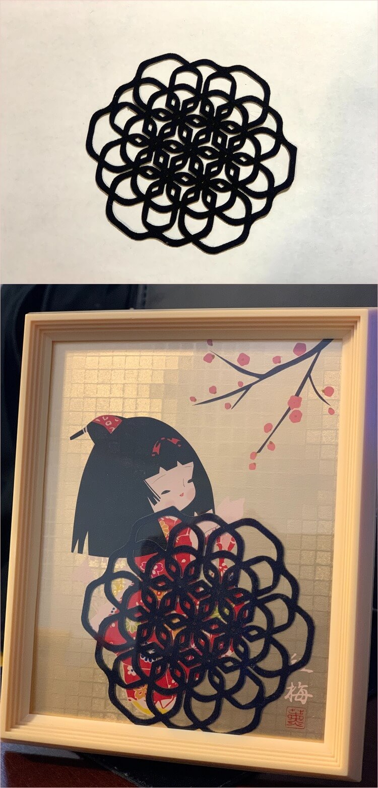
And here is how the design looked on the linen fabric that I would be using for my final project, very beautiful to me! I was impressed by how precise the laser cutting machine could get to.
The detailed laser cutting textile process would be documented on my Activity Log 2 of my Final Project section.
Files
Please find below the files that I made for this assignment.