
This work is licensed under a Creative Commons Attribution-NonCommercial-ShareAlike 4.0 International License
Week 2: Computer-Aided Design
Feb 9, 2021Summary
This week's assignments
- Model (raster, vector, 2D, 3D, render, animate, simulate, ...) a possible final project in 2D and 3D software ✔
- Show how you did it with words/images/screenshots ✔
- Include your original design files ✔
Resources Used
- 2D Sotware:Adobe Illustrator, Adobe Photoshop
- 3D Software: SOLIDWORKS, CLO3D
Skills Gained
- Raster design, Vector design, 3D modeling, Rendering
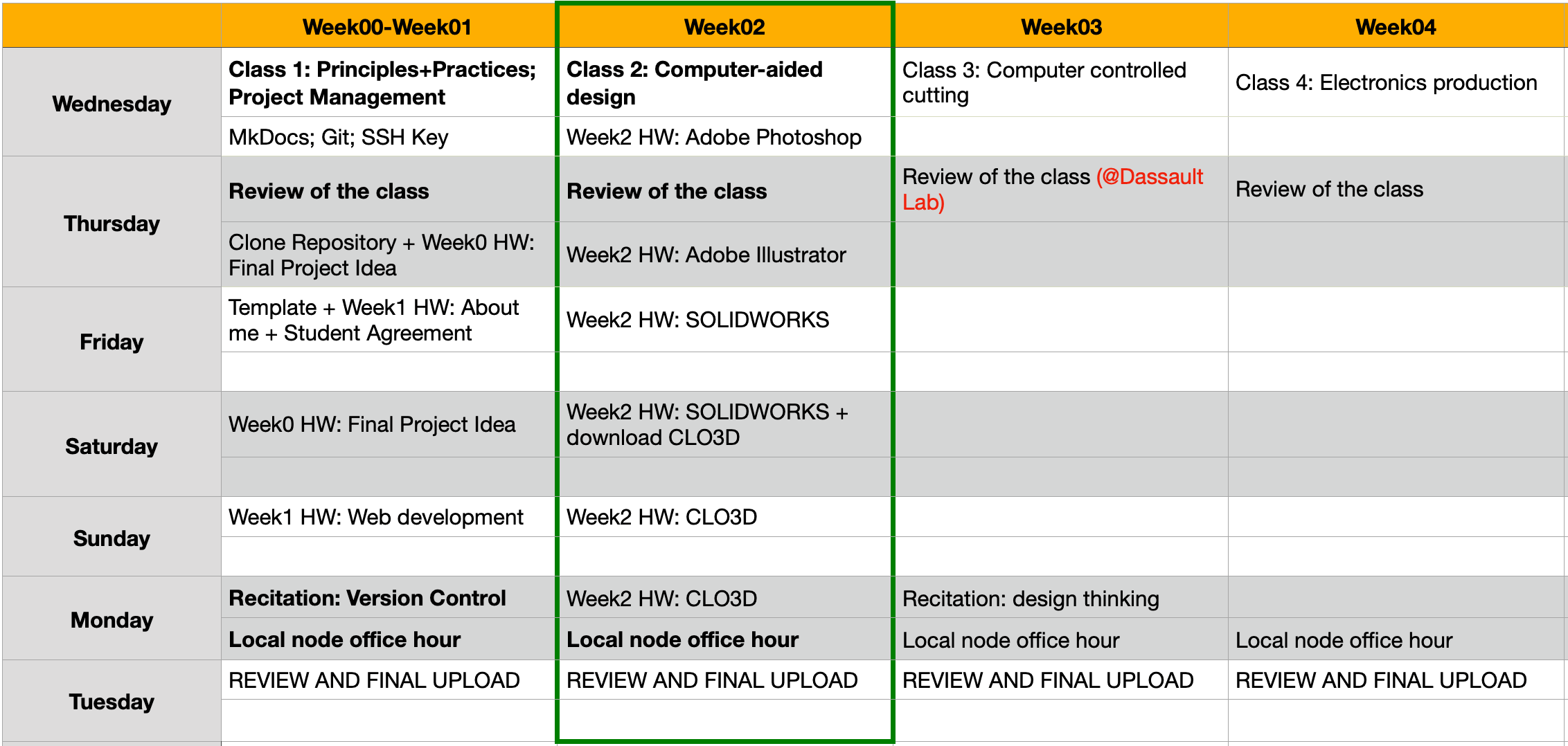
My Weekly Schedule
Experimenting With 2D Design Software
Adobe Photoshop
As I have already had Adobe CC software on my desktop, I chose to use Photoshop for raster graphic processing and Illustrator for vector graphic processing.
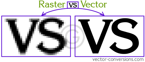
I have used Photoshop for basic image editing before but I didn't know the difference between Photoshop and Illustrator until this class. This week, I learned that raster graphics (.jpg, .png, .gif) are based on pixels (tiny squares) and are captured with a camera or scanner, while vector graphics (.svg, .dxf) are made up of paths (lines) and are used in CAD, laser cutting and CNC milling. The main advantage of using vector is that the resolution won't decrease even though the image is enlarged.
I was not sure how to begin my project with a raster program so I ended up doing something related to fashion fabrics instead 😄.
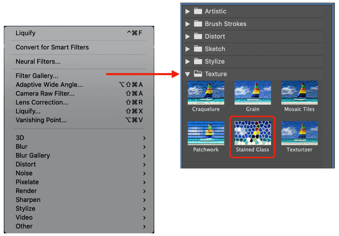
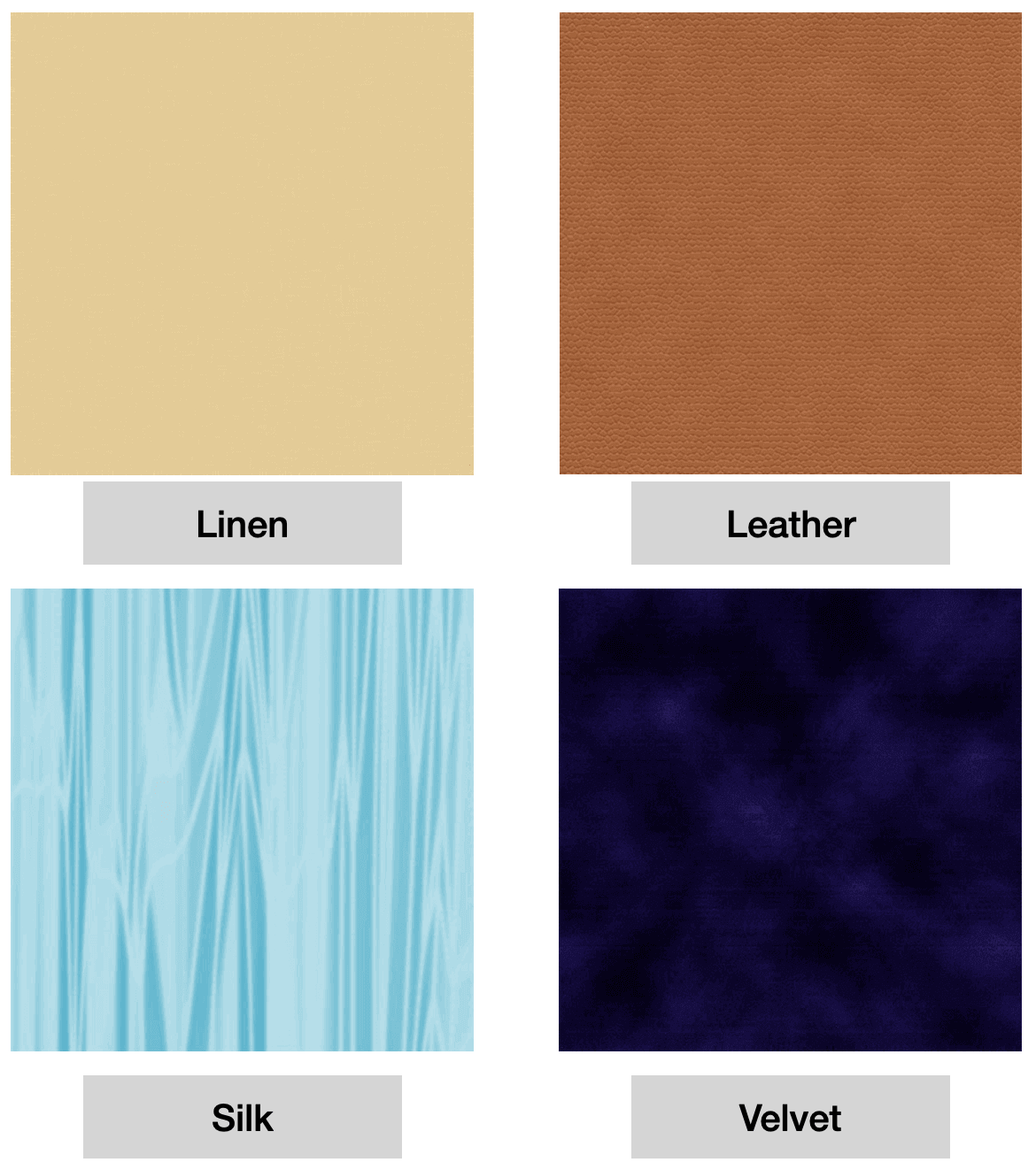
I followed some YouTube videos and learned to apply filter effects to create photorealistic fabric textures. There are various filter effects that we can use, for example, in order to create the looks and feels of a leather fabric, we would apply the "Stained Glass" texture effect to the layer before adding the color.
Another fun part was that, for every fabric texture, we would create two layers: one for the crosswise grain, and the other for the lengthwise (straight) grain; when we merged the two layers, we would see a realistic texture look of two distinct sets of threads interlacing to form a fabric.
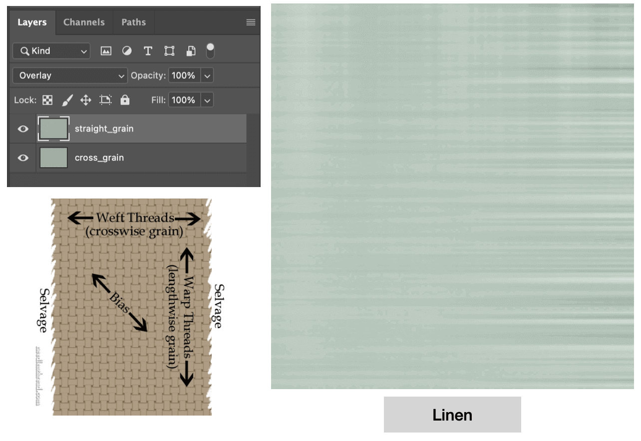
The image below shows the differnt fabric textures that I learned to create. I think it's fascinating that you can simulate fabric textures using a 2D software, and I will play with it more in the future!
Adobe Illustrator
For my project, I planned to involve textile laser cutting to create a "lace" or "eyelet" fabric effect, so the first step for me was to create a vector graphic of the patterns. I decided that the pattern for the bodice / skirt would be different from that of the waistband. To begin, I saved a stock image (.jpeg) that I liked for the waistband pattern, opened in Illustrator, and used the Image Trace tool to convert the raster image to a vector image.
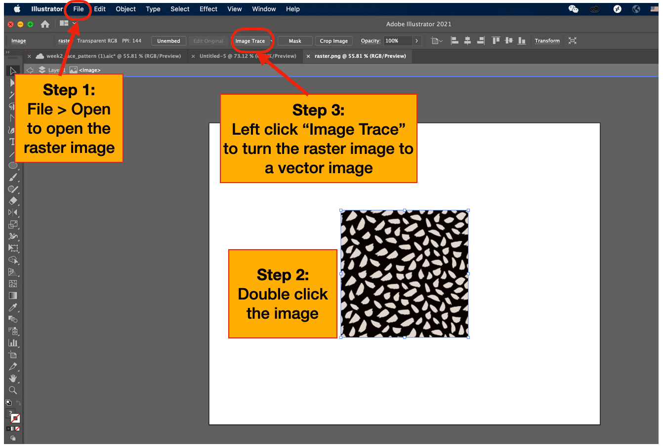
Once converted, the image colors became black and white only. I was able to enlarge the image without decreasing its resolution; however, I wanted to keep the origial shape and size, so I needed to make copies of the vector image to fill the paper. Then, I realized that the resultant pattern from the merged images didn't look seamless, and that was when I decided to detour and learn to create a seamless pattern in Illustrator.
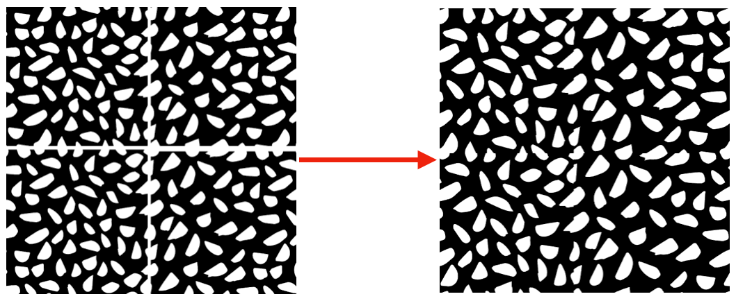
I watched several tutorials (1, 2, 3, 4 and 5) to get inspirations, and I decided to follow this tutorial to create the waistband pattern. I liked this one because the shape looked simple but still interesting enough 😺.
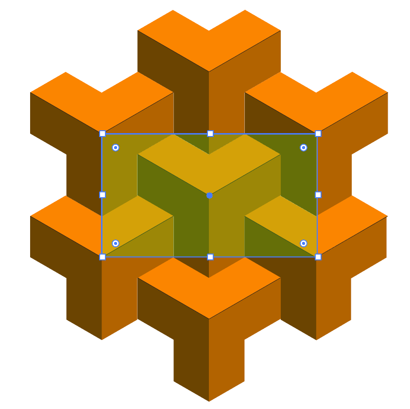
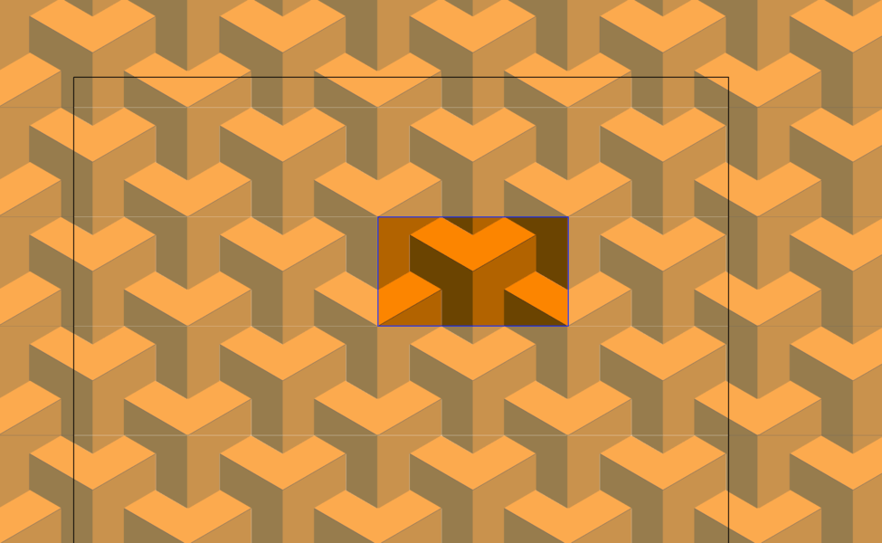
I started by adding a polygon and placed it to the center of the paper. Then, I used the copy, transform, reflect, and shape builder (boolean operation) tools to realize the shape I wanted.
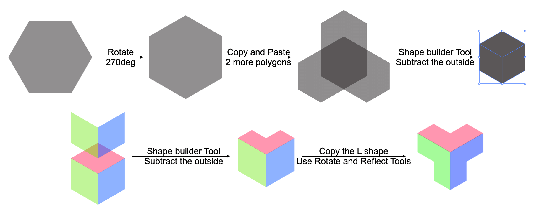
In the end I got a single rectangular tile that could be repeated seamlessly as the pattern for my waistband.
The last step for me would be to superimpose the lace pattern onto the waistband flat pattern piece so that they were laser cut together on the fabric. I was satisfied with the result, and I got to strengthen my Illustrator skills through this exercise!
Experimenting With 3D Design Software
SOLIDWORKS
As students at the Dassault Systèmes Lab, we were gifted with a one-year SOLIDWORKS Student Edition Premium License and have access to xDesign and xShape on-cloud CAD software, and since I had the most experience with SOLIDWORKS out of all the 3D design software, I decided to start there when modeling my project in a 3D shape.
Exercise 1: Package Box Design
I learned that I could create a package box using SOLIDWORKS Sheet Metal. As I didn't have experience with SOLIDWORKS Sheet Metal, the first step for me was to explore video courses. I followed this tutorial and created this package box.
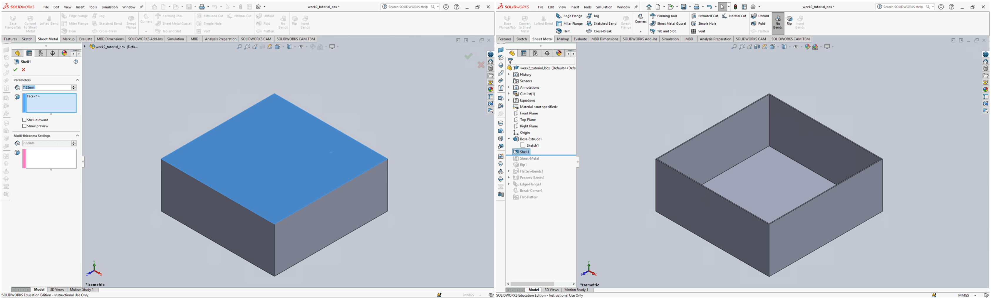
The package box is a SOIDWORKS Part model. I started by clicking the Sketch button and chose to work on the Front plane to create a Center Rectangle. Once I got out of the sketch mode, I started converting the 2D drawing into a 3D object by using the Extrude tool.
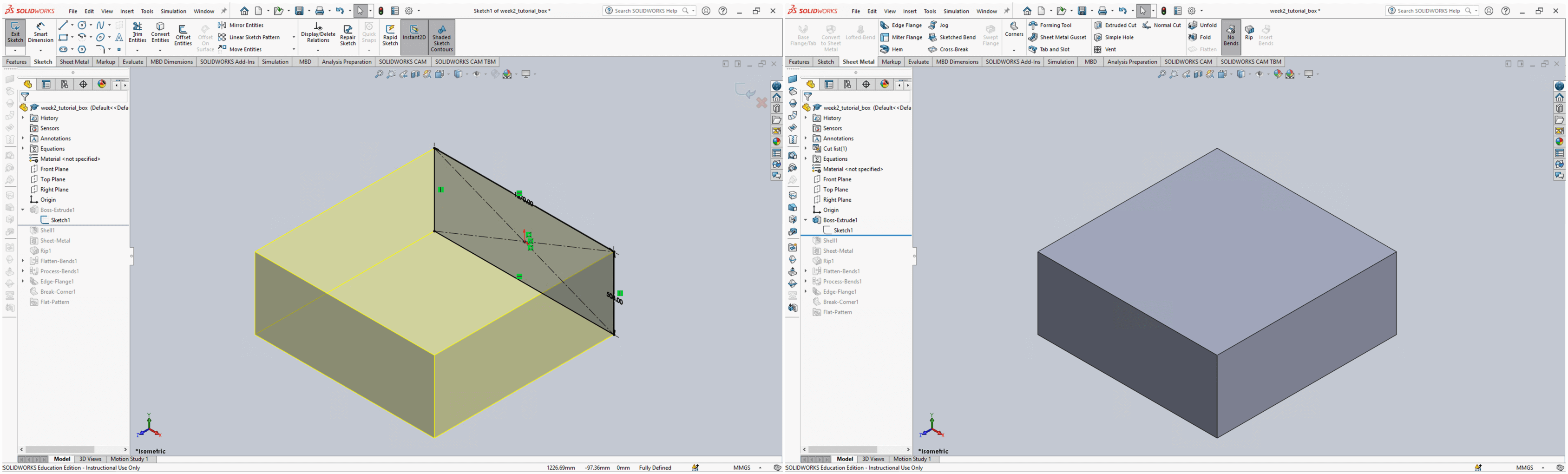
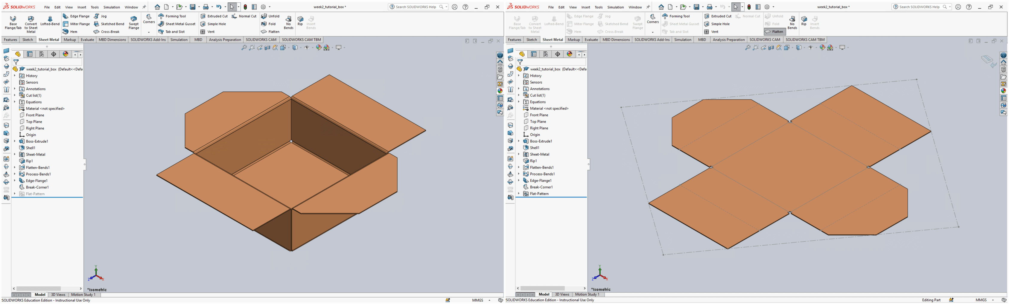
Next, I selected the top face of the cuboid and made it hollow using the Shell tool.
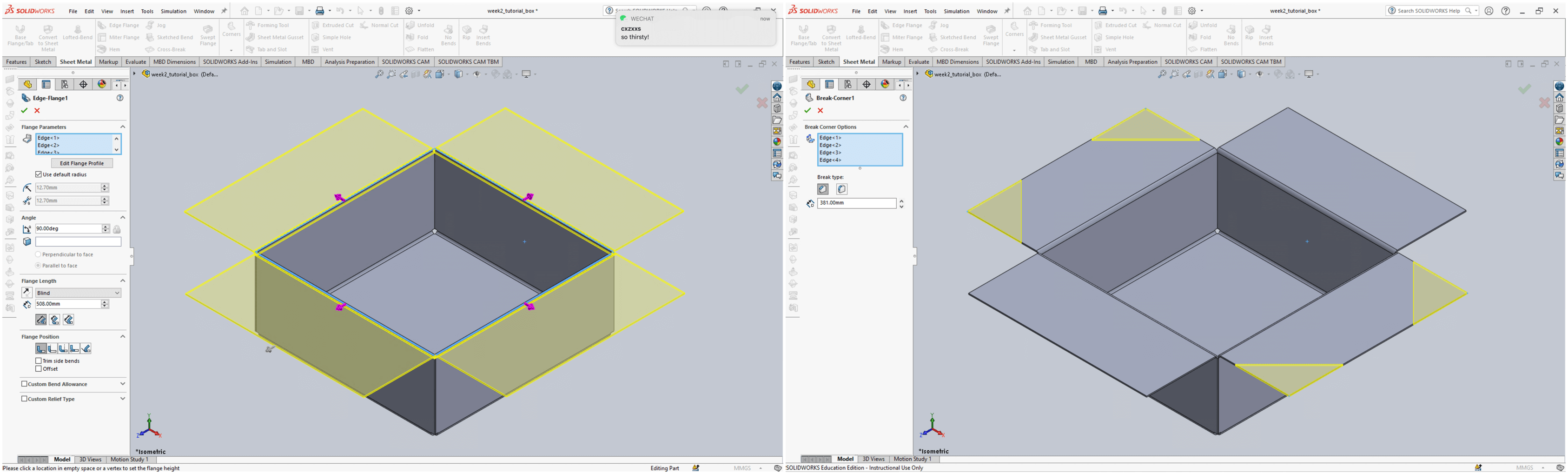
Then I used the Edge Flange tool from the Sheet Metal tab to add the sides to the box. In this step, I was prompted to select parameters such as the flange angle, length, and position. After creating the edge flanges, I used the Break Corner tool to either chamfer or fillet the corner(s).
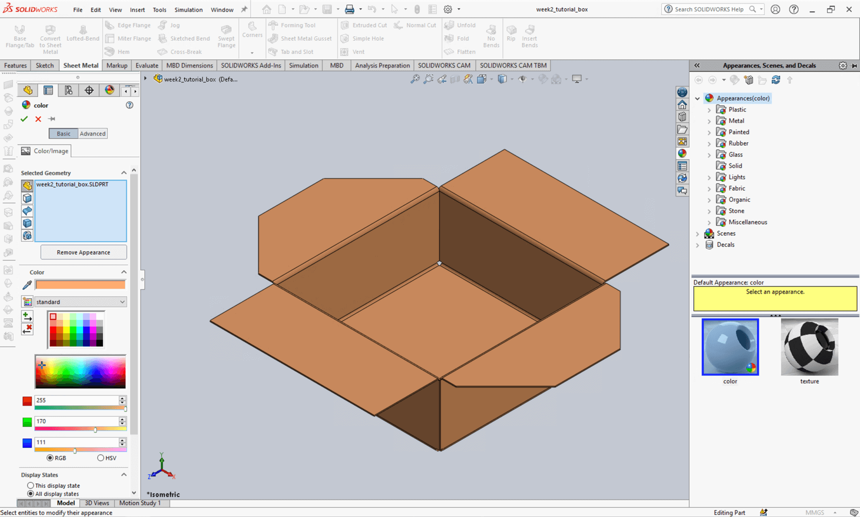
At this point, the package box was form. Next, I rendered the box with a latte color.
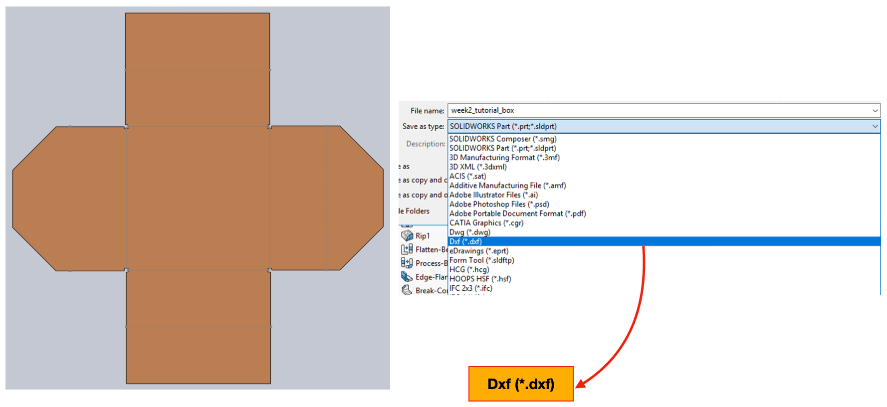
The flattened shape of the box can be saved as a DXF file, a vector file that can be used for laser cutting.
I uploaded this model to a platform called SketchFab, and this is how it looks.
The above package box that I learned from the tutorial was not a press-fit kit, and for my final project, I would like to fabricate a press-fit mailer box using a cardboard or a cardstock. I started with a hand sketch on a piece of paper, cut it and folded it into the mini prototype as shown in the image below.
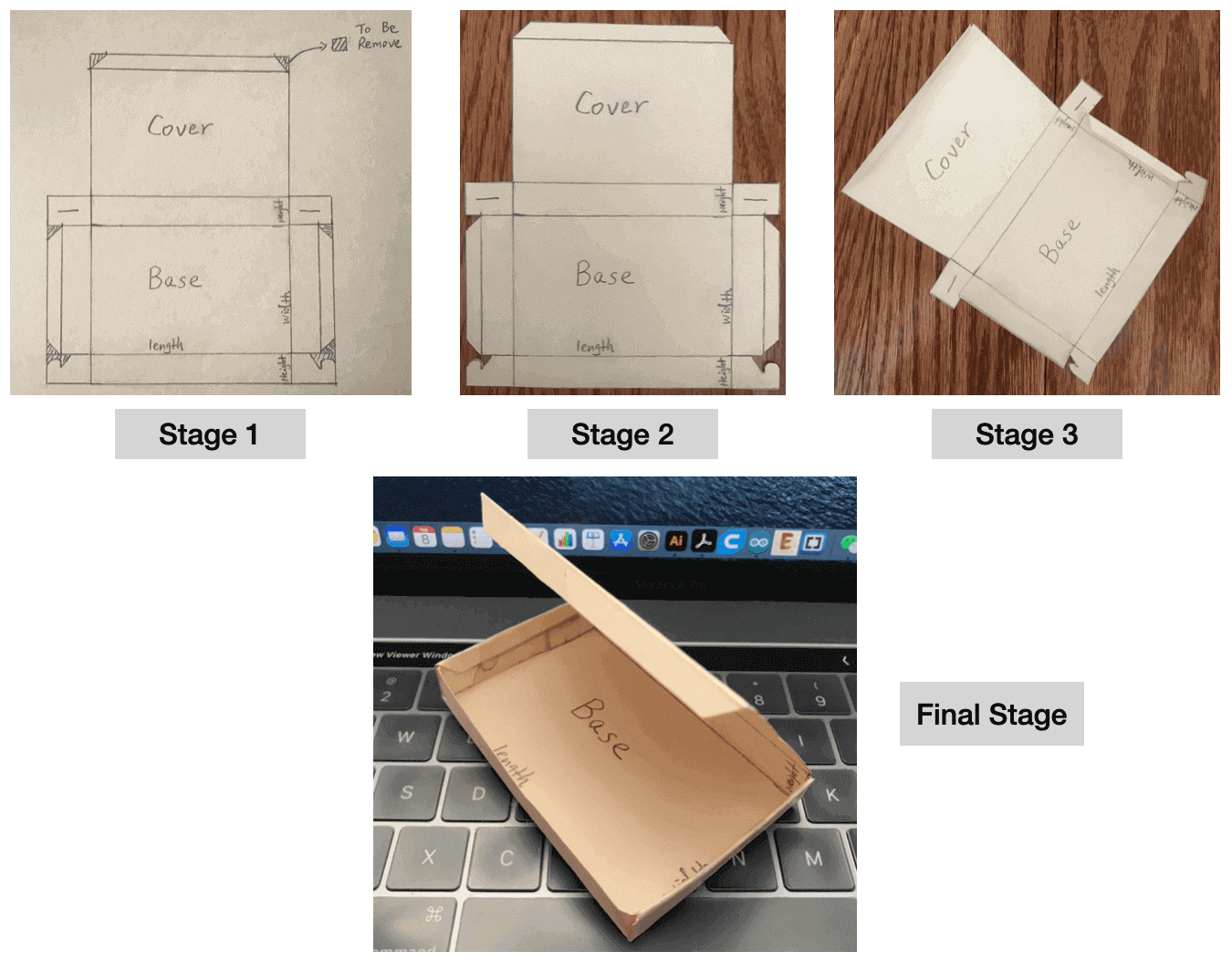
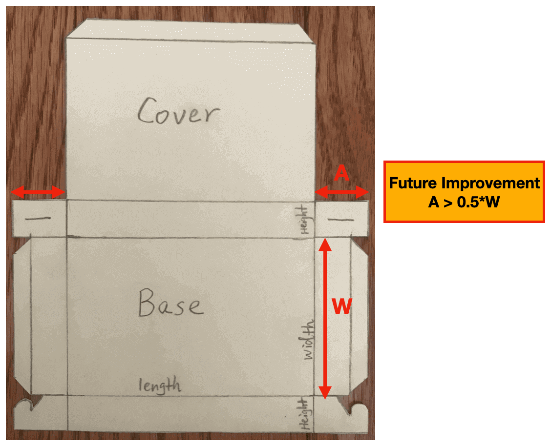
However, I realized that the length of the small side rectangles (A) were too short and thus they were not able to lock to each other. To rectify this, I had to secure with tape.
And this was the reason I liked the Flatten Tool so much, as it would help me to visualize how a package box was made as well as to validate my hand sketches.
I put off the 3D modeling of the package box and moved on to the other tasks for this assignment. The design process and the files for the final package box will be documented on the packaging page (Final Project Activity Log 8)
Exercise 2: Parametric Design for the Skirt Pattern
After I knew that I could export the faces of a SOLIDWORKS Part model as a .dxf file, I decided to use the 3D modeling environment as my first place to generate the sewing patterns for the skirt and the waistband.
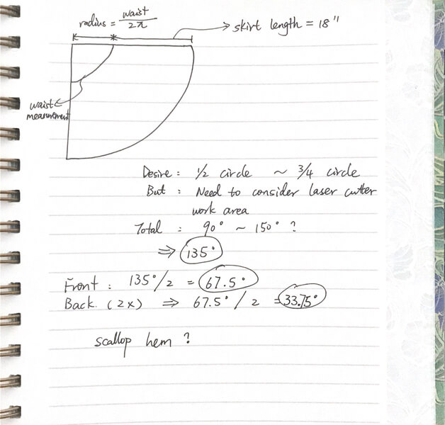
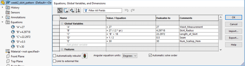
It would involve some calculations for the skirt piece, so I started by sketching a pie on my notebook and defined parameters such as the waist measurement and length of skirt. I then input these parameters and equations into the Global Variables table on SOLIDWORKS.
Then, I sketched the two circles on the Front Plane. Since I didn't want to have a full circle skirt, I added two straight lines to connect the edges of the disk as shown in the image below. As I hadn't defined the angle for the fan, I received the hint from the blue line indicating that the sketch was under-defined.
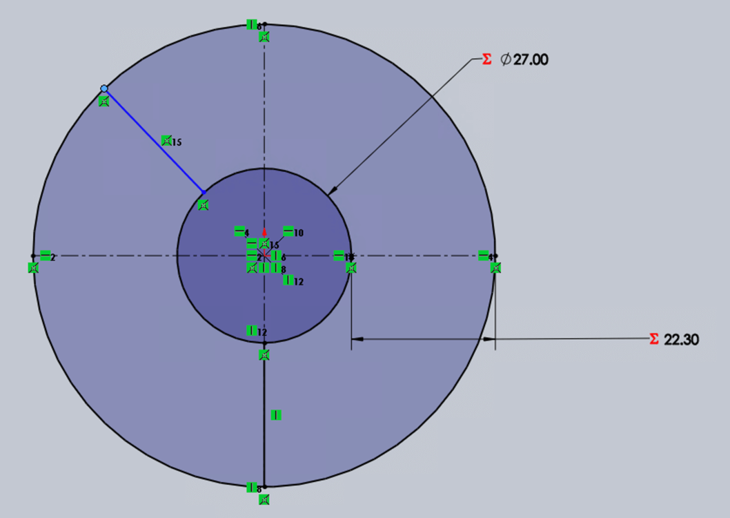
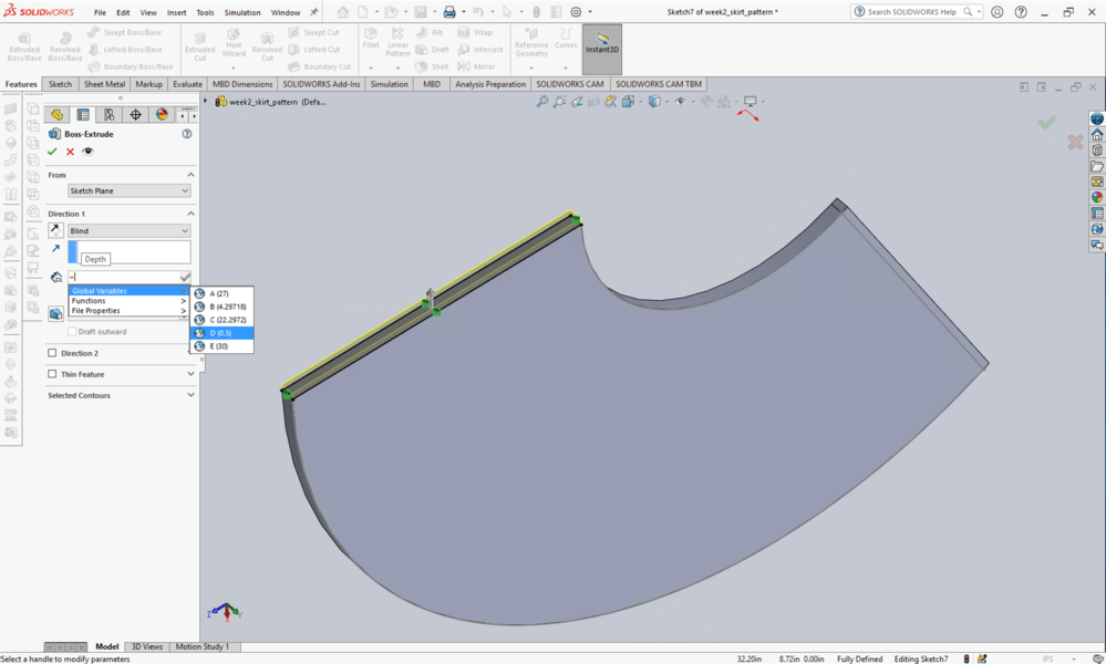
From my calculations for the skirt front piece, the angle would be 67.5°, so I input the angle to fully define sketch. I also extruded the sketch by 1 inch to make my following steps easier. The next step would be to add the seams, and for this step, I first selected the sides, then used the Covert Entities tool and the Extrude tool to include the 1/2 inch side seam (global variable "D") to my model
I also wanted to create a scalloped hem and processed it with a leaser cutter, and here entered my internal debate of the fabric choice for the dress, basically I was debating whether or not I should use natural-based fabric.
I am hoping to use linen because I think that it may be easier to work with electronics when using a cotton / linen fabric instead of polyester, however I learned from this note that the nature (i.e. linen) fabric would end up with burnt edges.
Since I was not sure yet, I planned to experiment with the fabric candidates in the coming weeks on the laser cutting machine.
Back to my scalloped hem... in order to create the scalloped hem, I started by sketching a 1-inch circle and constrained its edge with the Tangent tool to the bottom of the skirt and the side seam.
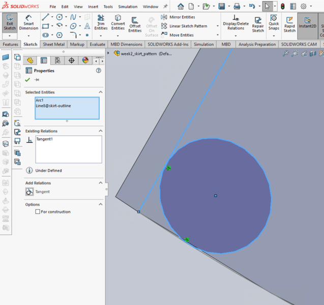
I created a second circle using the Equal and Tangent constraints. Using the Extrude Cut tool, I would be able to get the first cut of a scalloped hem.
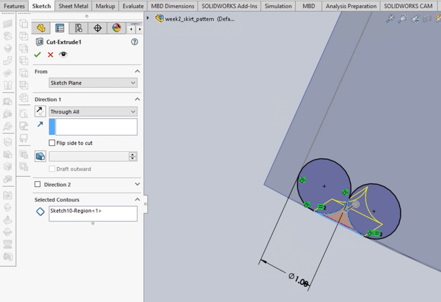
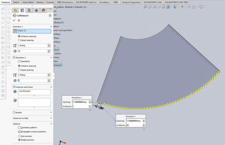
Then, I used the Circular Pattern tool to repeat the process, and for this step, the preview tool was very helpful handy as it allowed me to to adjust the spacing of extruded cut.
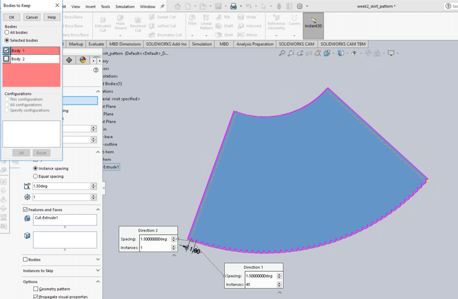
Once I was happy with the circular pattern result, I hit the green checkmark on the top left corner, and I was prompted to select the bodies to keep. At first I was confused, but then I realized that I unintentionally created a surface body when I extruded cut the last scalloop. For this step, I selected "Body 1", which was the skirt piece I wanted to keep.
Another way to rectify this issue for me would be by increasing the number of repeating feature on the previous step. Doing so, I would be able to cut the excessive material instead of getting the extra surface body.
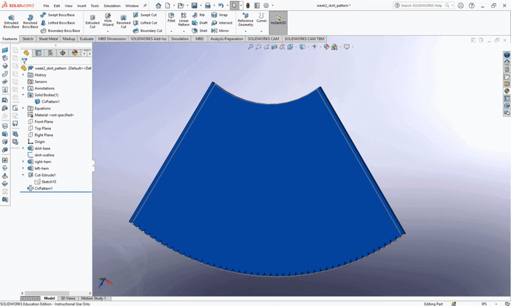
Next, I rendered the skirt with a cotton (blue) color for a photorealistic effect.
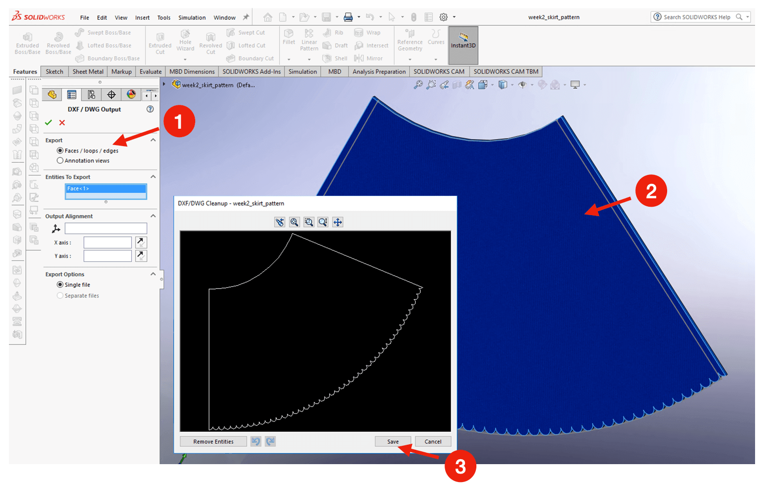
And finally, I exported the front face as a .dxf file for laser cutting.
In the coming weeks, I want to experiment with a few things for the textile laser cutting:
- The laser cutter settings for the fabric
- The edge finish of the laser cut textile
- The size of the scallop
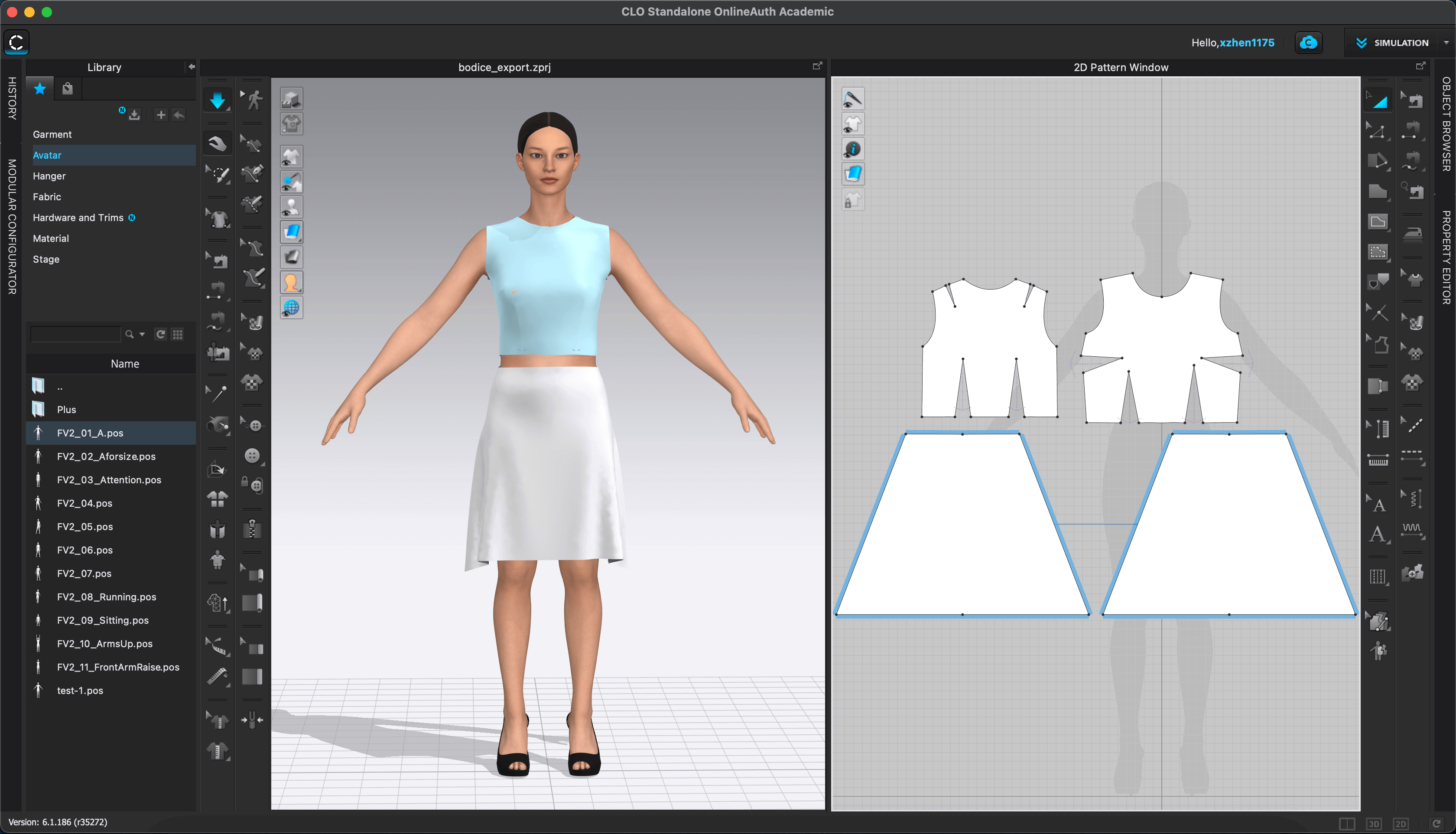
CLO3D
I had a stretch goal to explore fashion design software, and thankfully, I found the time to experiment with one of them. Last week, I discovered Valentina and CLO3D, which are very powerful tools that allow pattern creation using either standard sizing tables or an individual's set of measurements. Valentina is a great open-source tool with a simple user interface, while CLO3D is a commercial virtual draping software with a 30-day trial but offers great support to students.
After doing a deep research, I chose to work with CLO3D because I liked that it has a virtual, true-to-life garment visualization engine that allows the user to test the fit of the patterns and experiment with different cloth materials before making the first cut.
Similar to learning other tools, I started with taking tutorials and interactive sessions to get myself familiar with the basics. I watched some videos in CLO3D's YouTube Channel, and I was so intrigued that I signed up for a Udemy CLO3D course during the weekly Udemy flash sale 😹.
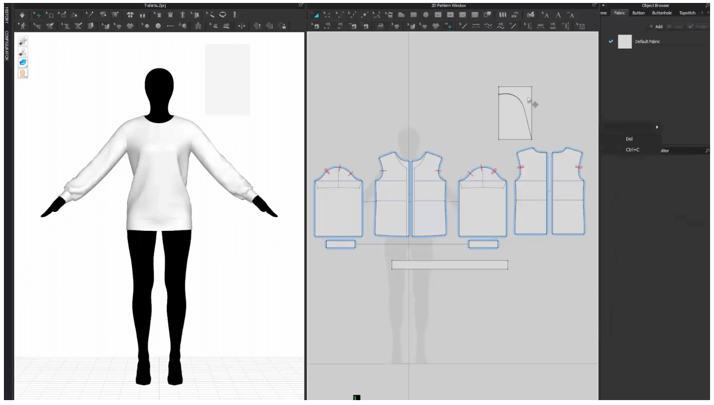
The class was intensive and I learned a lot! In the Flat Pattern Drafting section, I learned to create a bodice sloper. A sloper is like a foundation pattern that our clothing designs are based. For me, I will be adapting the sloper to add princess seams.
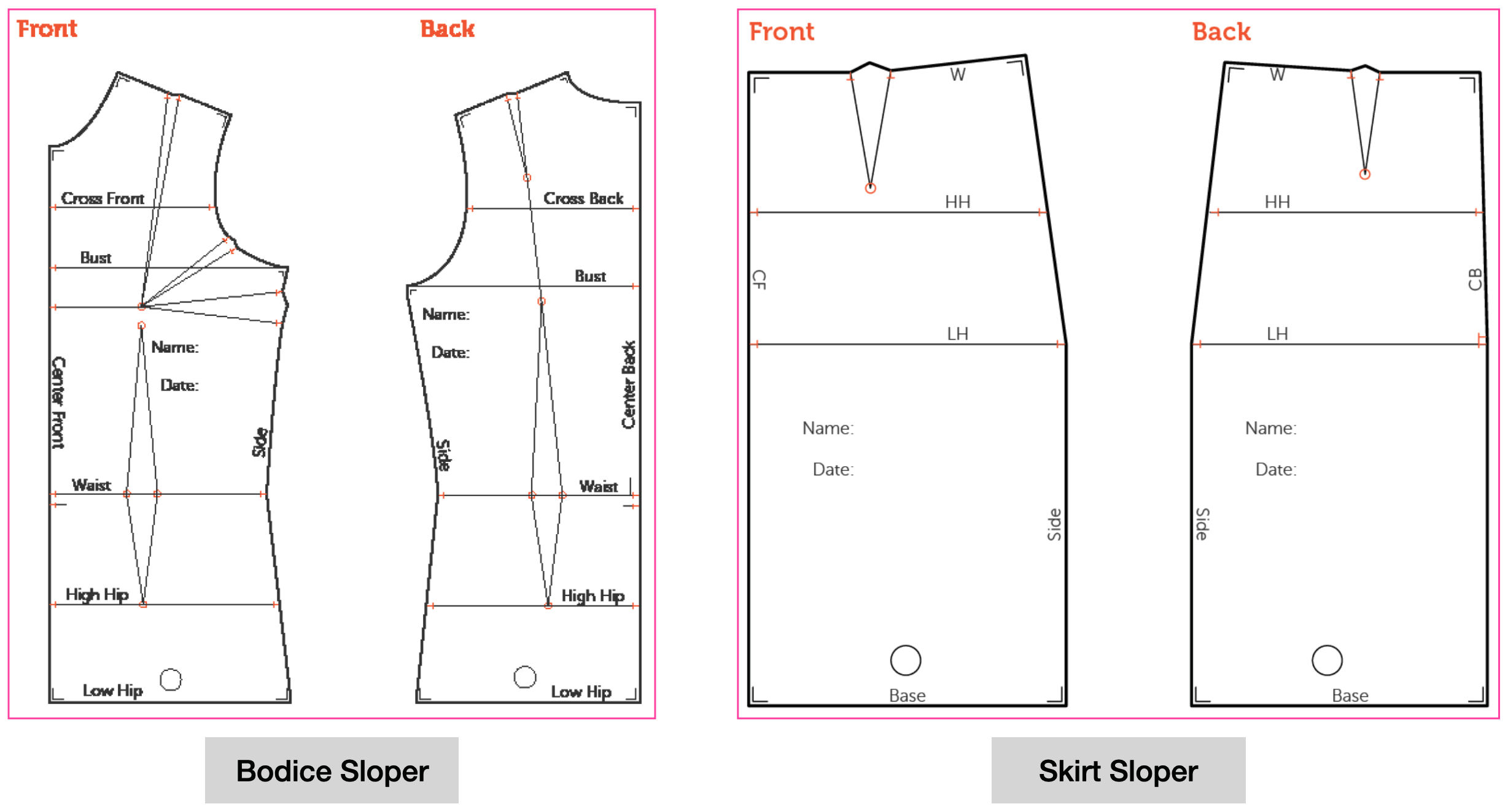
Let's see how a bodice sloper was created.
Step 1: Choose the avatar, sizing, and the fabric.
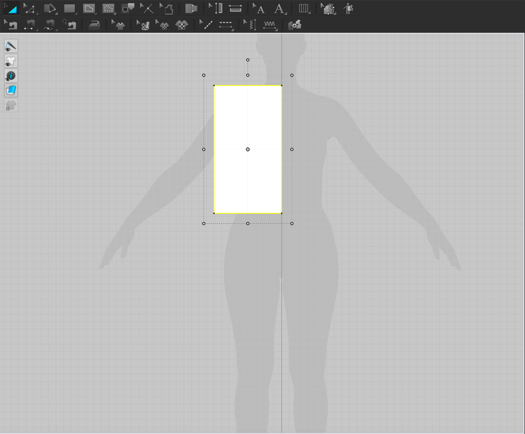
Step 2: Create a rectangular block and align the top edge to the left shoulder on the 2D Pattern View Interface. For this step, we will need to check back the size spec and use the largest measurements as the width and length of the rectangle.
In this case, the chest is the longest part in width, and the center back body length is the longest height, and since we are only only on half block, so we need to divide the chest width by 2 when we input the width for the rectangle.
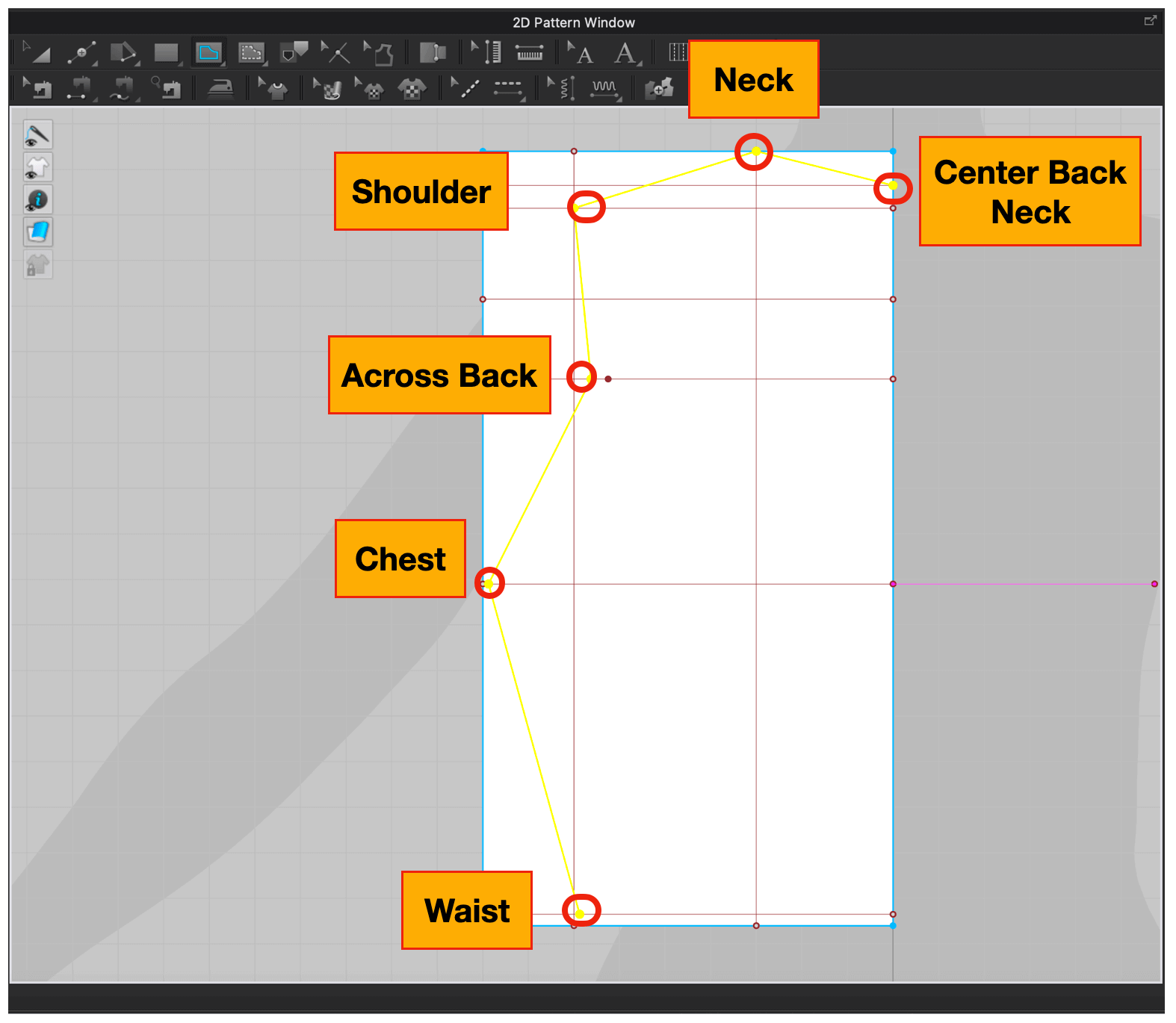
Step 3: Use the Edit Pattern tool (keyboard shortcut Z ) and Add Point Splitline tool (keyboard shortcut X ) to add guidlines and markings.
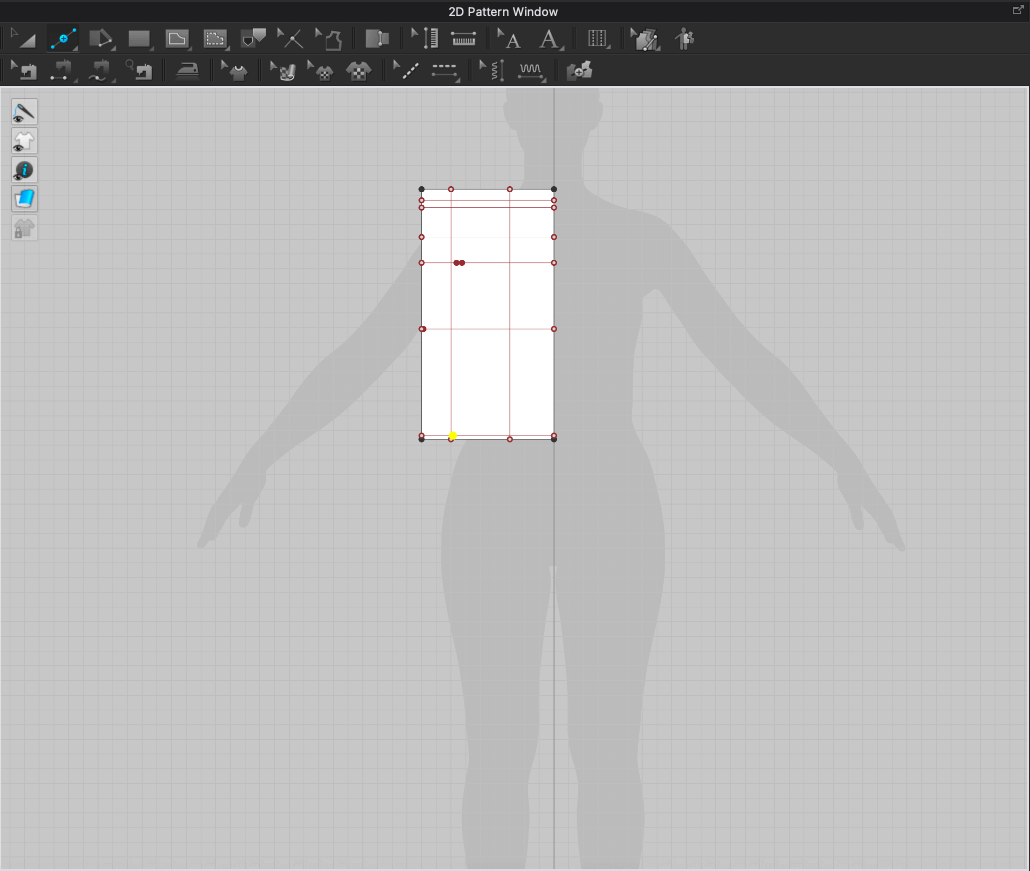
Step 4: Use the Internal Polygon Line tool (keyboard shortcut G ) to connect the points with straight lines. In here, when we connect the Across Back point and the Chest point, we will be able to build the armhole.
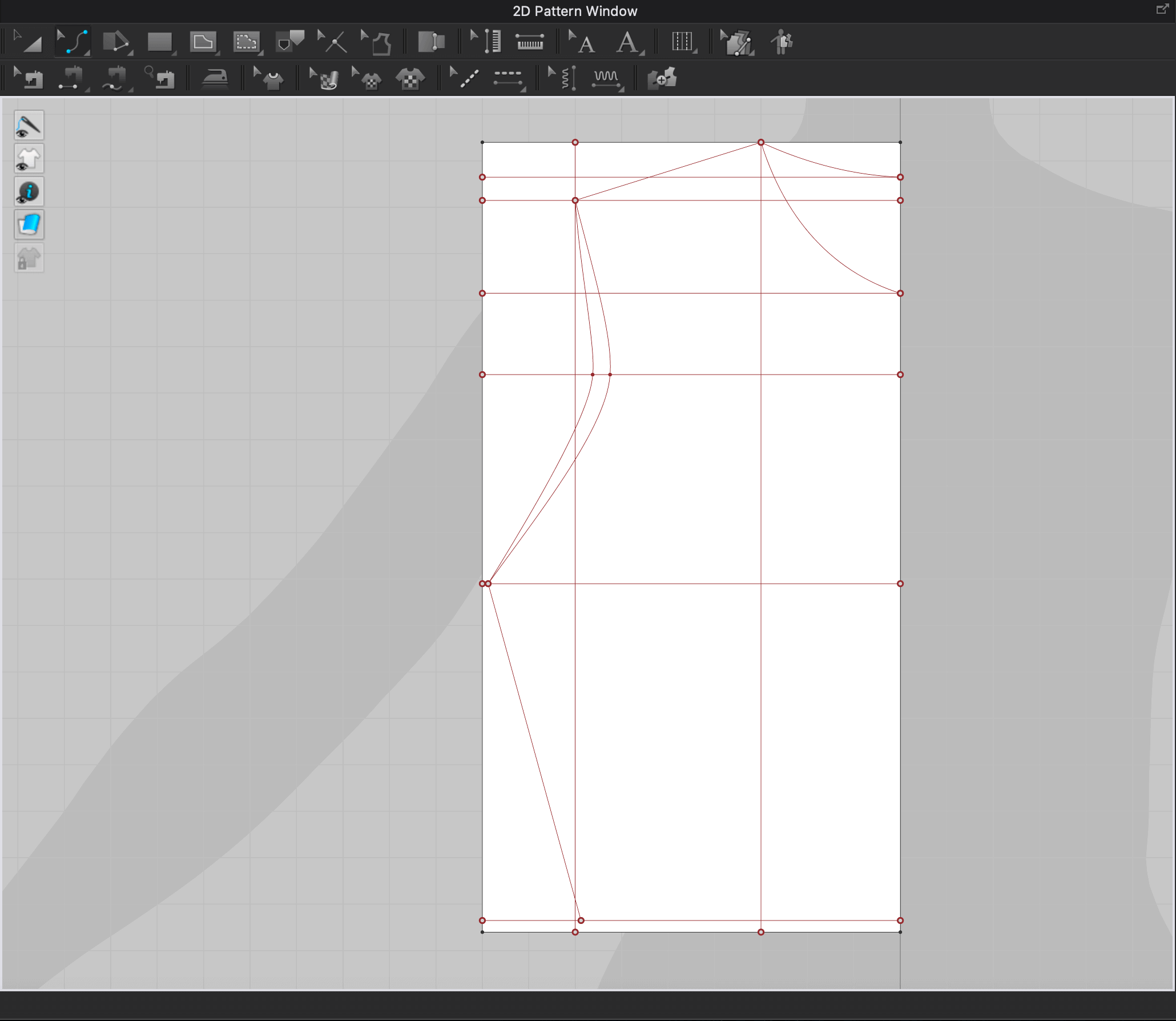
Step 5: Use the Edit Curvature tool (keyboard shortcut C ) to curve up the neckline and the armhole. The image below shows the front half block combining with the back half blocks, so the next step is to separate them.
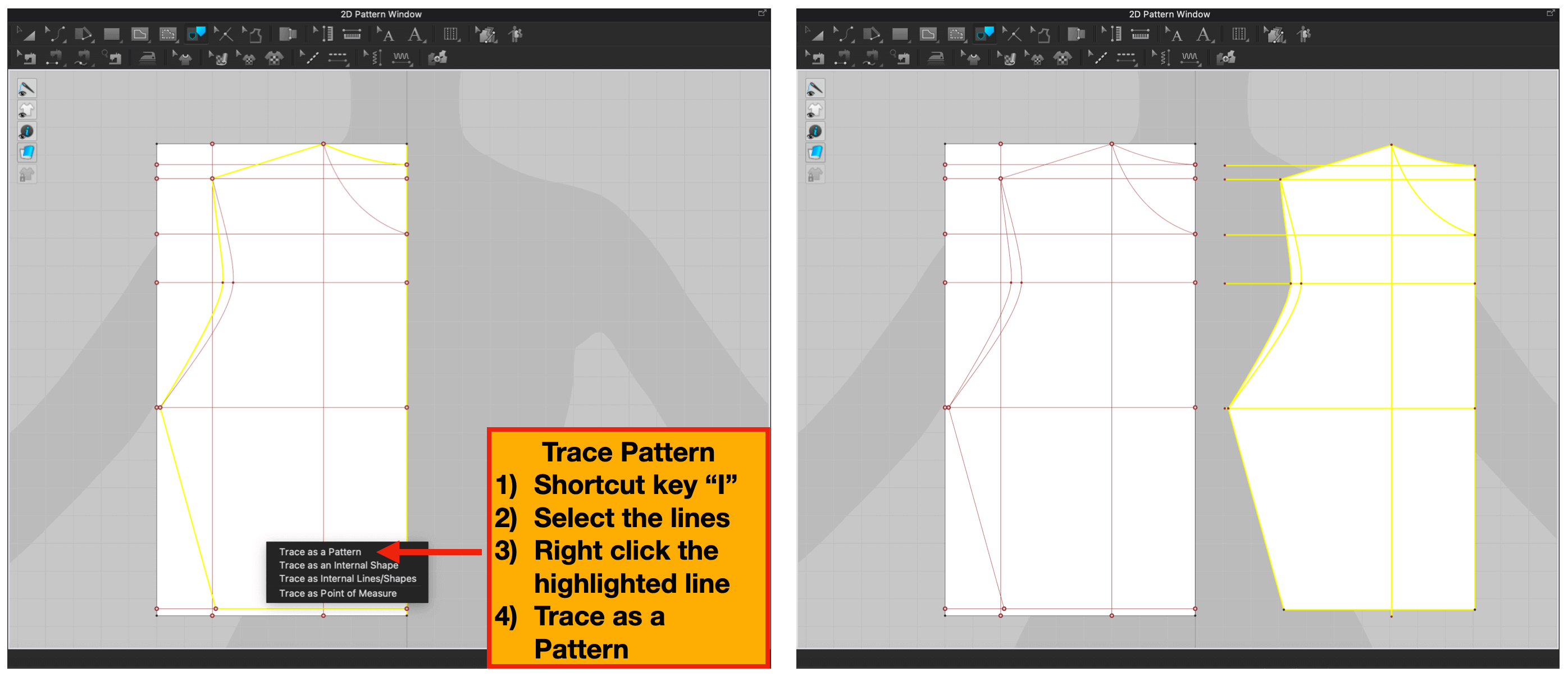
Step 6: Use the Trace as a Pattern tool to realize the initial shape of the sloper, we will do this step twice, one for the back half block, and the other for the front half block.
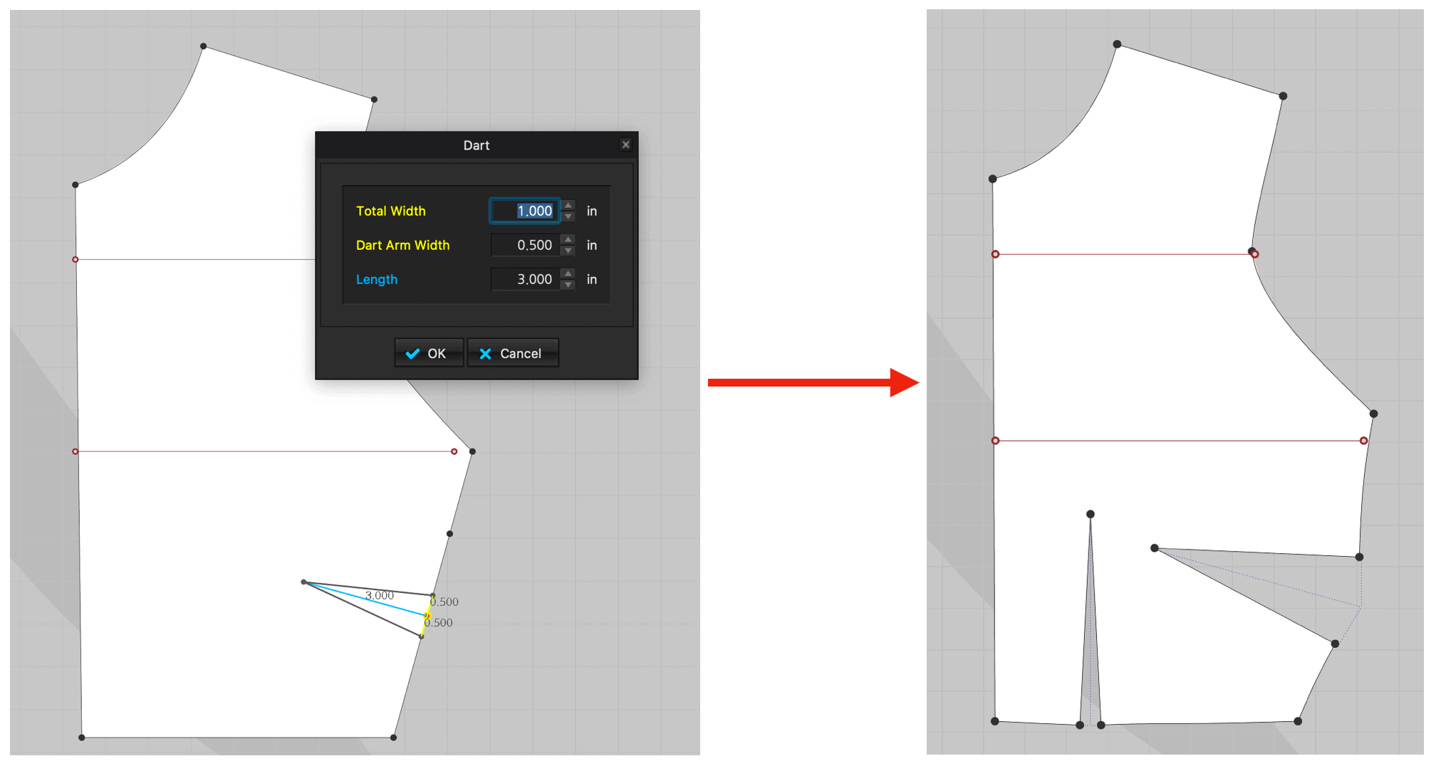
Step 7: After removing the extra dots and lines, we will add the darts using the Add Dart tool.
The whole process was very mathematical and I was very appreciative with the built-in calculator from the program. The pattern that I followed along was using a US Standard Size ASTM Missy Size 10, thus I would need to adjust the pattern for my size.
My next step is to manipulate this pattern to include the princess seams, and my design process.
May 16, 2021Update: during Week 16, I had the chance to complete this exercise in CLO3D. I also laser cut the fabric and sewed a prototype dress for my final project. Please visit my Week 16: Wildcard Week documentation for more information.
Files
Please find below the files that I made for this assignment.
- Fabric Texture Design Files
- Adobe Photoshop Files (.psd) **externally hosted due to large file sizes (over 10 MB each)**
- Linen (.jpg)
- Leather (.jpg)
- Silk (.jpg)
- Velvet (.jpg)
- Geometric Pattern Design Files
- Package Box Design Files
- Skirt Pattern Design Files
- Bodice Pattern Design Files
- CLO3D Sewing Project **externally hosted due to large file sizes (over 10 MB each)**