Week 3. Computer Controlled Cutting
Introduction
There are two laser cutters at the 3DEXPERIENCE Lab: Trotec Speedy 400Flexx and Epilog Laser Mini. We received training for the Trotec Speedy 400Flexx machine and the information that we collected is based on this machine.
- Model: Trotec Speedy 400 flexx
- Software: Adobe Illustrator + JobControl
- Work area: 40 x 24 inch
- Max. Workpiece height: 12.0 inch
- Laser power - CO2: 60 - 120 watts
- Laser power - Fiber: 20 - 50 watts
Group Assignment
The group assignment this week was to characterize the focus, power, speed, rate, kerf, join clearance and types of the Trotec Speedy 400 laser cutter in our lab.
We split this up into 4 tasks one for each of us.
Focus, Power, Speed, Rate
Author: Jonathan
Kerf
Author: Nick
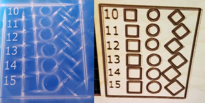
To test the kerf I created a test file that had a grid of shapes square, circle, and diamond that range from 10x10mm to 15x15mm in 1mm increments. I drew this file in InkScape and brought the .svg file to the laser computer. Jonathan operated the laser for the first setup since he was the only one in our group who had never used a laser cutter before. He opened the file in Adobe Illustrator and “printed” it to send it to Job Control which runs the laser. We did have to go back to Illustrator because Job Control requires all cut lines to be 0.001 inch or thinner and my original lines were not thin enough. I wanted to cut this test pattern in different materials to see if that had any effect on the kerf so we setup our first cut in cardboard. Our laser has auto focus and presets for cut an engrave settings so getting the machine configured was a breeze. The cardboard cuts worked great. Jonathan had to to teach a class so I took over as laser operator from here.

Next I setup to cut the same pattern in 1/4 inch blue acrylic. I refocused the laser and changed the material presets but then decided I should take pictures of the settings for cardboard and got distracted and didn’t set it back to acrylic before I sent the cut to the laser. This meant I wasn’t using nearly enough power to cut through the acrylic. I quickly realized my error, grabbed another acrylic scrap, fixed the material settings and recut the part. This time it worked as expected.
Lastly I setup a cut in 3mm plywood. The plywood we had was slightly warped so I used some aluminum scrap as a weight to flatten the warp. I changed the material settings and ran the cut again. The cut wasn’t quite perfect, some of the diamond shapes didn’t cut all the way through. I could push them out by hand or cut them with a box cutter so it was very close. I though that I might not have readjusted the focus when switching from acrylic to plywood. I hit the autofocus and it made a big adjustment, so I figured that was the problem and I ran the cut again. This time though it was clearly way out of focus. It took a bit of playing around with it but we figured out that the auto focus system is just a break beam sensor that runs across the far edge of the bed and the aluminum block was crossing that beam throwing off the focus.
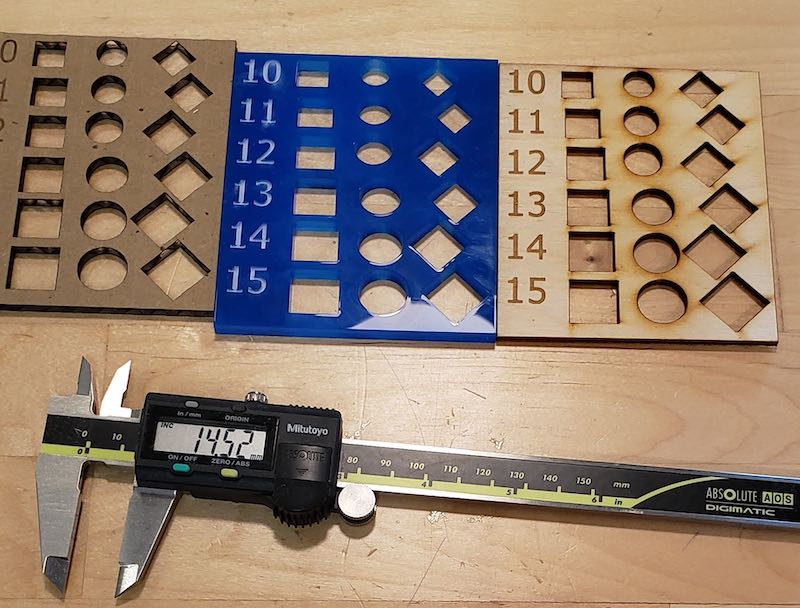
I then measured all the cut outs from the 3 different materials and calculated their kerf.
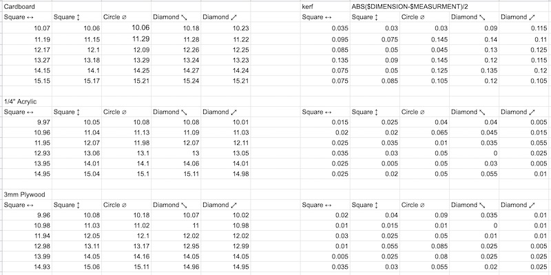
After taking taking the measurements and looking at the calculations these kerf values seem too small. We’ll keep looking at the other tests for better values. I also was suggested another method of measuring this value which I didn’t have time to go back to the lab and try but I did try using another laser cutter. That method can be seen here.
Joint Clearance
Author: Linda
The goal of this experiment was to test the best fit of a joint clearance based on the material thickness. The materials that I tested on were:
- 3mm Plywood
- Cardboard
- 1/4" (5.5 mm - 6 mm) Acrylic
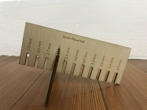
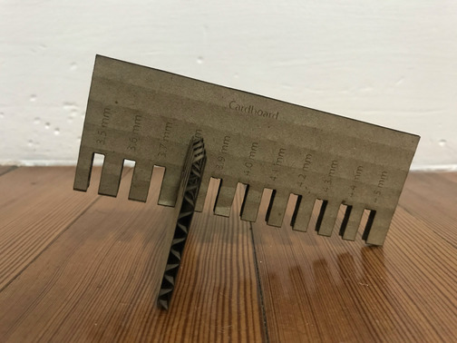
For each material, I created a “comb” on Adobe Illustrator to test different slot widths for press-fit. I made sure the stroke thickness for the cutline was 0.001 inch and the color was true red (R/G/B = 255/0/0), I also made sure the color for the engraving elements was in true black (R/G/B = 0/0/0). The slot range for each material are as follows:
- 3mm Plywood: starting at 2.5 mm wide and increasing by 0.1 mm increments to 3.5 mm wide
- Cardboard: starting at 3.5 mm wide and increasing by 0.1 mm increments to 4.5 mm wide
- 1/4" (5.5 mm - 6 mm) Acrylic: starting at 5.0 mm wide and increasing by 0.1 mm increments to 6.5 mm wide
![]()
I learned about the focus, power, speed, and rate of the laser cutter through “trial-and-error” on a 3 mm plywood. Initially, the machine was only engraving instead of cutting because I accidentially introduced a black outline (a second layer) under the red cut line, so the machine interpreted that as engraving. I was also using the default setting when I made my test cut and I quickly learned that the default setting didn’t work for small fonts (size 11). To recitify this issue, I lowered the speed but increased the power for the engraving setting. I also encountered the issue of not getting the focus right. With this experience, I have learned how laser cutting works and followed the rule of “measure twice, cut once”.
![]()
When the joint clearance files were all cut, I was ready to test the fit and I carried out this task in two steps. First, I inserting a slot of material piece A to the same slot width of material piece B and decided which one fit the best (fit snugly but not overly tight). After I knew which slot fit the best, I then used a 6-inch dial caliper in the lab to measure the slot width and compared it with the material widith. Then, the kerf would be calculated as follows:
kerf = (material_thickness - slot_width) / 2
The reason for dividing by 2 was because we needed to account for the left edge and the right edge of the slot.
In the end, I settled on the following settings for this test, and these were also the settings I would use for my individual assignment.
| 3mm Plywood | Power | Speed | Frequencey |
|---|---|---|---|
| Engraving | 55 | 30 | 1000 |
| Cutting | 90 | 0.7 | 500 |
| Cardboard | Power | Speed | Frequencey |
|---|---|---|---|
| Engraving | 50 | 90 | 500 |
| Cutting | 100 | 2 | 1000 |
| 1/4” Acrylic | Power | Speed | Frequencey |
|---|---|---|---|
| Engraving | 90 | 85 | 1000 |
| Cutting | 100 | 0.4 | 6500 |
I decided that the best fit for each material would be as follows and these are the values that I will end up using for my parametric design:
- 3mm Plywood: best fit is the 2.8 mm slot
- kerf = (material_thickness - slot_width) /2 = (3.0 mm - 2.8 mm) / 2 = 0.1 mm
- cardboard: best fit is the 3.8 mm slot
- kerf = material_thickness - slot_width) / 2 = (4.0 mm - 3.8 mm) / 2 = 0.1 mm
- 1/4" (5.5 mm - 6 mm) Acrylic: best fit is the 5.2 mm slot
- kerf = (material_thickness - slot_width) / 2 = (5.5 mm - 5.2 mm) / 2 = 0.15 mm

Joint Types
Author: Griffin