Vinyl Cutting
First Attempt
I have used a vinyl cutter before to make simple stickers. I have used InkScape to create vector graphics and the InkCut extension to send them to send them to the cutter. I was a bit thrown off by the software for the Roland cutter at the DS lab not being able to import a vector graphic. I created a graphic that I wanted to cut out of thermal transfer vinyl to put onto T-Shirts for my nephews, but that lab didn’t have any in stock. Greg said he has some at the lab where he works and I could go visit there when he gets back from vacation. Until then I played with some sticker vinyl at the lab to try out the tool chain. I took a screenshot of an astronaut figure I had made in tinkerCAD last summer. I still had it in my head that I needed a vector so I used InkScape’s traceBitmap function to vectorize the screenshot.
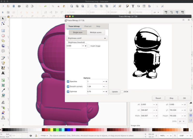
This did create a black and white version that would work better for the Roland software. I opened the B/W graphic in the Cut Studio and used its create outlines function.
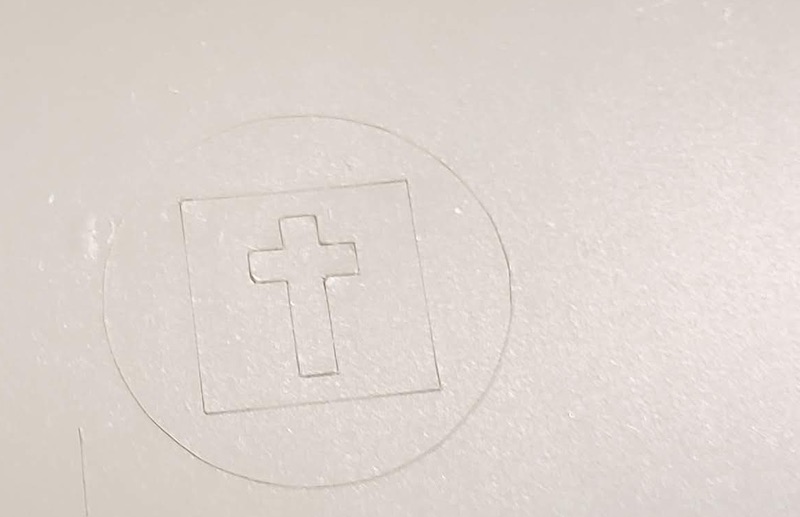
I poked around with the machine settings even though we had them set up fairly well from our training earlier that day. I set the force to 70g and the speed to 30cm/s. I ran a test cut using the machine’s test button and it came out fine. I ran a test of my graphic and It didn’t work well tearing up the vinyl in several places.
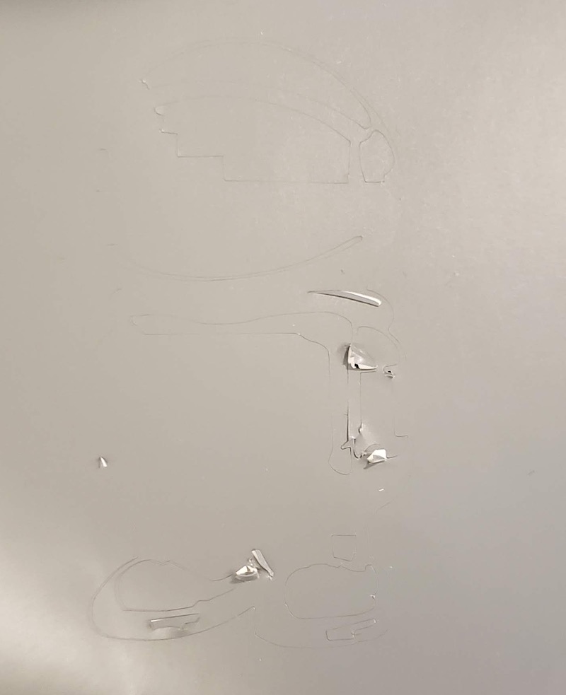
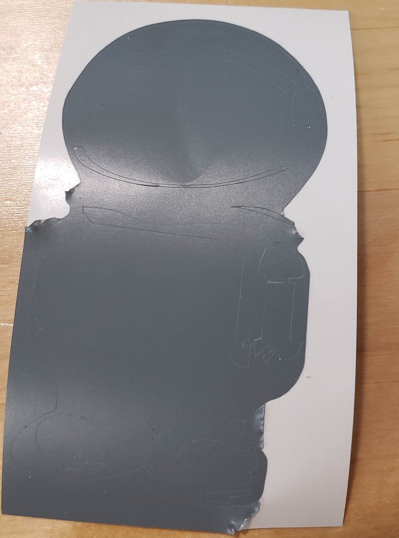
I tried reducing the speed and force to 20cm/s and 50g in several steps repeating the cut each time. I got a cut that looked good but when I tried to weed it I found the vinyl hadn’t been cut all the way through. I was out of time in the lab and stopped there. I suspect that the details in my graphic were too small to be cut reliably. I will make a simpler graphic for my next tests.
Second Attempt
Since all we had was sticker vinyl, and I understood the toolchain for the cutter at the DS lab I decided to save myself the longer trip to the lab and use a vinyl cutter at Artisan’s Asylum.
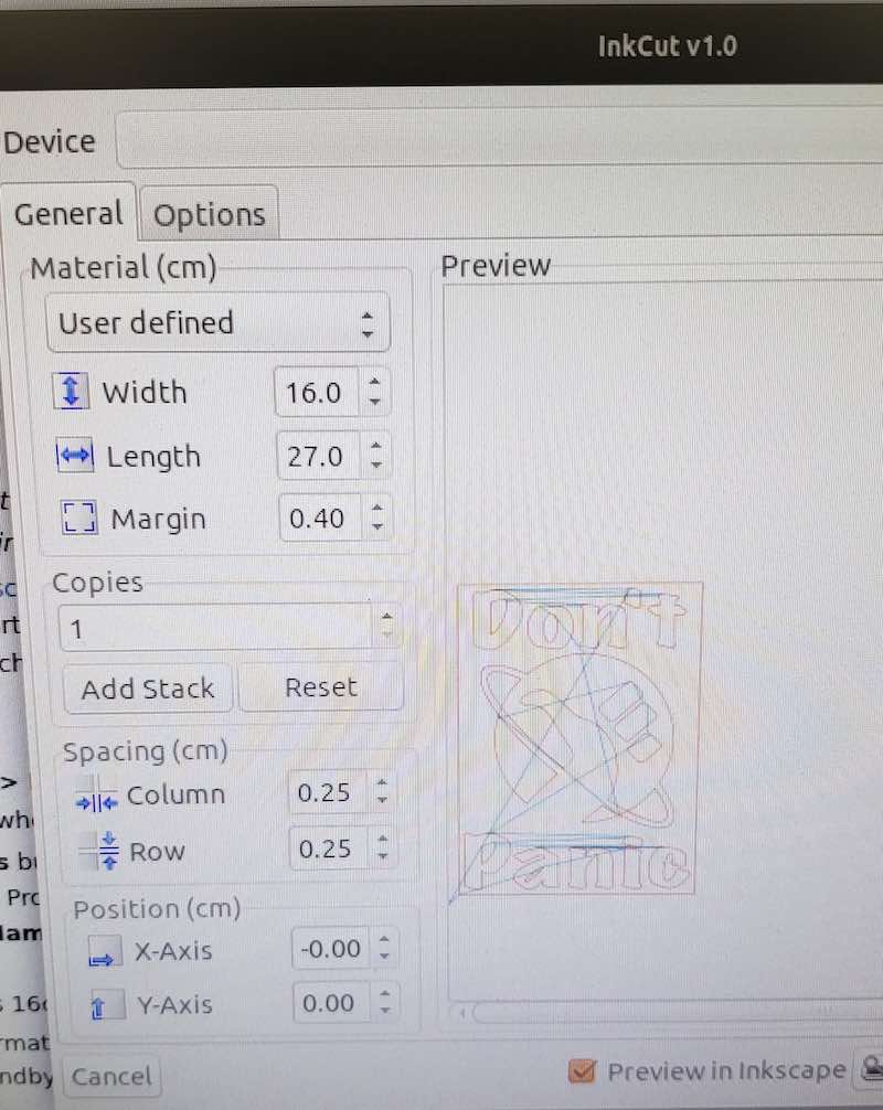
This machine is much simpler than the one at the lab. There is no adjustment for speed or force. It is run using the inkCut extension for InkScape. I may try to get this running with the vinyl cutter in the lab because no one seems happy with the Cut Studio software. I wanted to make a simple sticker graphic. The first thing that popped into my head as a sticker to put on my Fab Academy notebook was the tagline from the Hitchhiker’s Guide to the Galaxy, “Don’t Panic”. This seemed oddly fitting. A quick google image search gave me a plethora of options for a logo to use and I liked the thumbs up on a planet version. I downloaded one version and ran it through InkScape’s trace bitmap function but as is often the trouble with that the resulting vector is way too complicated. Instead I redrew the logo using circles and the bezier curves tool. I added some text and was ready to cut. The version of InkCut is fairly old as is the computer it’s running on. This cutter needs a parallel port, who’s got those anymore? The software has a few quirks so I initially got some error messages that I had grouped my vectors to make rotating them into orientation easier, but once I ungrouped everything and loaded in my vinyl of choice it cut just fine. When I first plugged in and configured the printer I hit the test button which cut a square on to the vinyl right where I was going to put my logo so my first cut had an annoying square cut out of it.
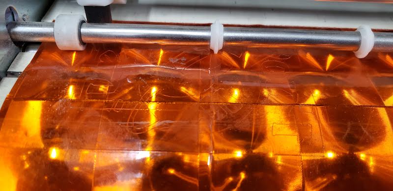
I though I could flip the vinyl around and get it to still fit on the same small scrap piece I was using. That ended up overlapping my previous cut so that the logo came out fine but the top line of text was overlapping on both cuts. I grabbed another piece of vinyl and decided to make a two colored piece the text would be one color and the logo another. I could also use parts of the logo as a registration mark to get the two to line up with the transfer tape when I apply them to my notebook. Weeding was mostly fine but there were a few spots where there were creases in the vinyl scrap I used caused the bottom of the D and n in Don’t to rip. I also lost the apostrophe. I pulled off everything but the planet logo from one of the orange cuts and then pulled off the planet and background from the green cut. I left the fingers in the logo of the green vinyl to line up the green text with the orange logo when I combined them.
![]()
The transfer tape was pretty old and gave me some trouble but I got the orange logo stuck on pretty easily. The green text was a lot of small parts and was more difficult to get onto the transfer tape. the o in Don’t tried to escape but I got it lined back up close enough. Once I had the green on the transfer tape I lined up the 3 fingers with the spaces in the orange planet logo and stuck it down. Then I removed the 3 green fingers and cut a new apostrophe from a bit of scrap by hand.
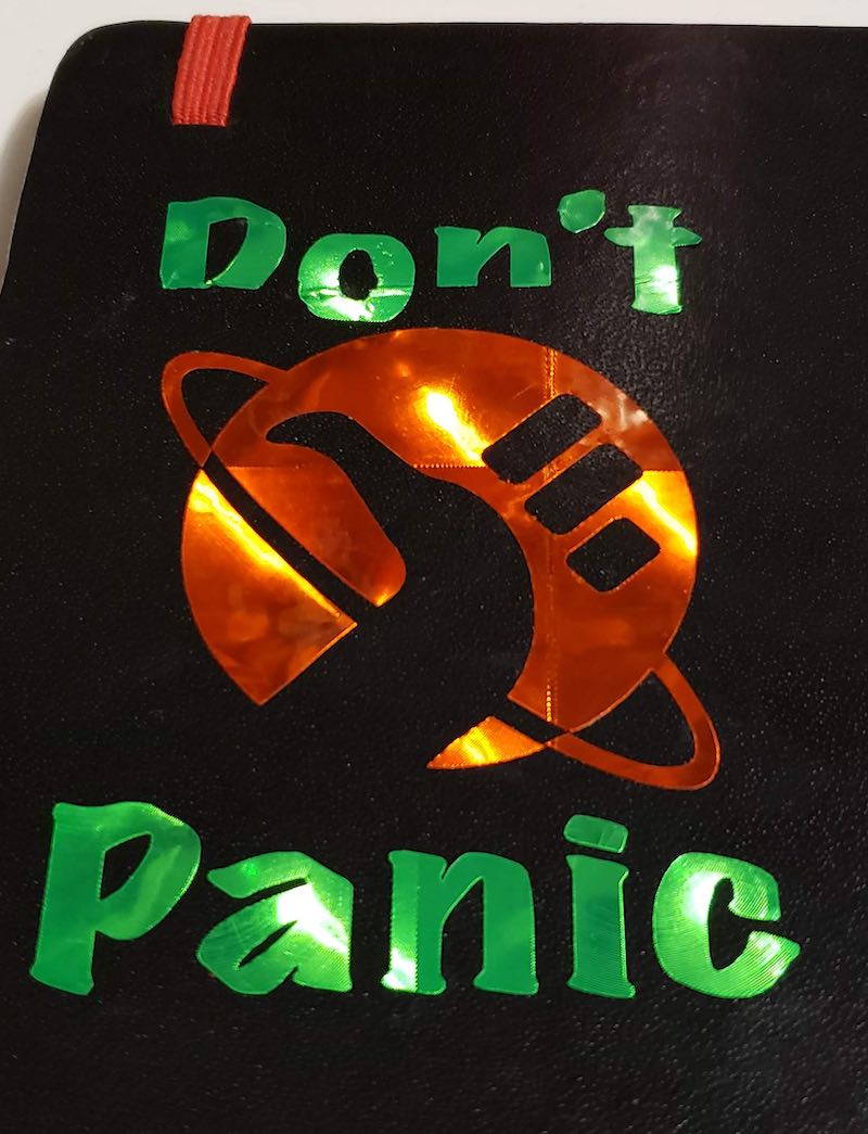
It’s not perfect but a worthy addition to my Fab Academy notebook. I hope I don’t need the reminder too often but it will be there if I do.
Laser Cutting
DS Lab Laser
At the Dassault Systemes 3D Experience Lab I worked with my classmates to characterize the laser cutter there. See our full report on our Lab Page.
Artisan’s Asylum Laser
I took the work we each did and repeated a simplified version of it at Artisan’s Asylum, the maker space where I work to complete the project on the laser there.
Specs and Software
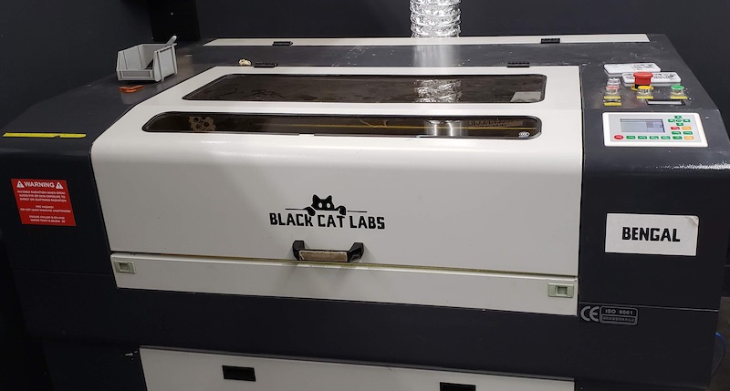
Artisan’s Asylum has 2 Black Cat Labs 80 Watt Laser Cutters with a 600x900mm bed. The laser is focused manually by moving the work surface up and down. The control software is Lightburn. I teach the safety training class on these lasers so I am very familiar with them. The user interface on Lightburn makes much more sense to me than Job Control on the laser at the DS lab. Directly importing and manipulating vector files is an important part of my workflow.
Kerf Test
I started characterization with some kerf tests. I did all of these test and my initial construction in 2.8mm thick cardboard. There was only a preset for 4mm cardboard so I had to adjust the settings to get a clean cut. After a few tests I settled on 150mm/s and 50% power.
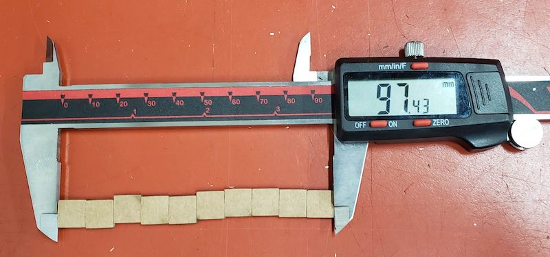
Instead of cutting the pattern of holes I made at DS I just cut 10 10x10mm squares, lined them all up and measured the total length. This was a bit tricky to measure on cardboard because I had to make sure the corrugations were all lined up along the axis I was measuring so that the squares of cardboard would not overlap each other. They should have been 100mm. They actually measured 97.43mm. A total of 2.57mm of missing material due to kerf. Divide that by 10 for .257mm missing from each square and divide that by 2 for the two cuts left and right of each square leaves me with .1285mm kerf.
Joint Clearance Test
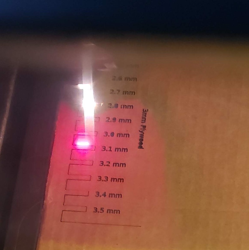
I used Xiaolin’s joint clearance test file available at the lab page above and cut out the comb that ranged from 2.5mm to 3.5mm. The 2.5mm slot fit together the best. The 2.6mm slot fit ok but was a bit loose. 2.5 would be my target for a good press fit with this material. Since the cardboard is 2.8mm thick I set my kerf at 0.15mm which lines up close enough with my measurement from the previous test.
Example Joints
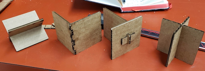
To test this value I loaded up Griffin’s example joints file, that he will upload to the lab page. All I had to do was edit the parameters for material thickness to be 2.8mm and kerf to 0.15mm. The sketches automatically updated and I exported a .dxf File. I copied this file to the laser computer and imported it into Lightburn. This was the first time I had exported a .dxf file from Fusion and I noted that it included construction lines and actual lines. I was able to easily identify and delete the construction lines and cut an example of each joint type. They all fit perfectly on the fist try which validated my kerf measurements.
Parametric Laser Cutting
Inspiration
Now that I have good kerf measurements I needed to design my parametric construction kit. I wanted to design something more artistic to leave my comfort zone of hard edged engineering. As its near valentine’s day I’ve been seeing ads on Instagram for Love Pop’s pop up paper flowers. I know some folks at Artisan’s Asylum who used to make jumbo sized versions of their pop up cards for them and though that flowers might make an interesting construction. And I could surprise my partner with flowers and an art project all at once.
Starting at the Bottom
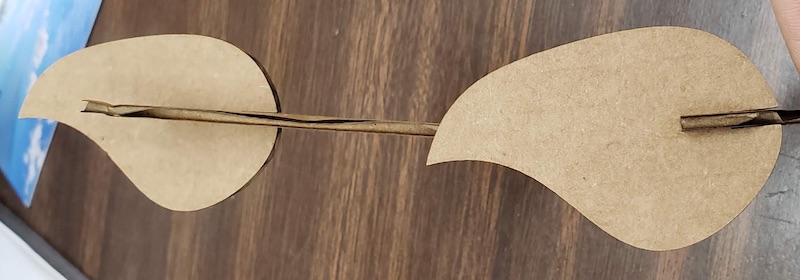
I initially started too complicated. I was trying to start with a curvy stem that had a place to attach a flower at the top and leaves on the sides. I designed a stem and a leaf with a parametric slot fit. This did work but I wasn’t happy with my ideas for the actual flower. I should have started at the flower and worried about the stems, leaves, and connection pieces later.
Flower Power
After cutting the stem and leaf I set them aside and sought a bit more inspiration on where to pick up again with the flowers. I googled “paper flowers” to get some ideas and the blue flower in this image caught my eye as a simple starting place. I should create a simple sunflower like shape with a circle at the center of a set of petals and a simple connector for the two.
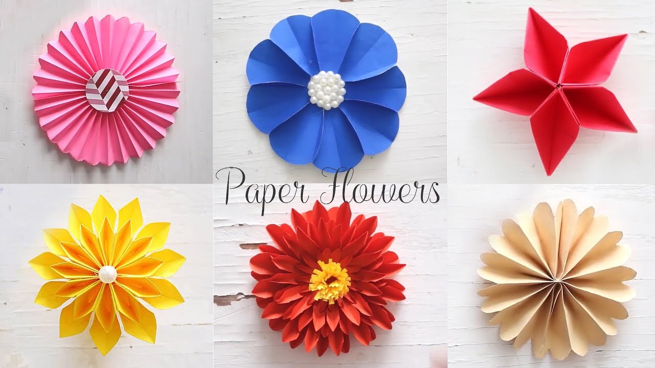
This is the thumbnail for this video. I didn’t actually watch the video the picture alone got me on the right track.
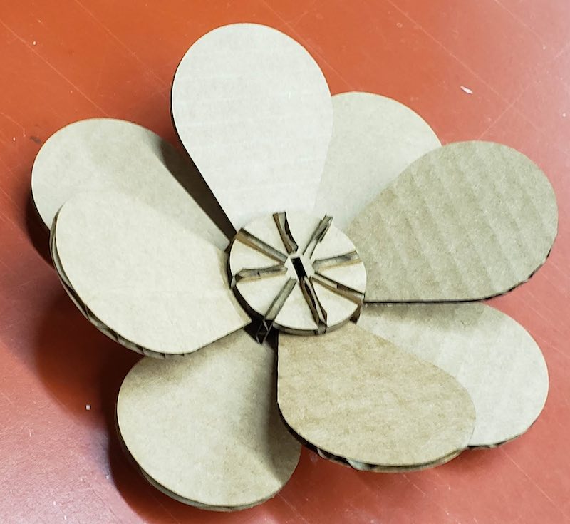
I created 3 components a circle for the center of the flower, a flower petal, and a connector to attach the petals to the circle.
Center Circle
The circle has a parameterized slot repeated using a circular pattern to create 8 attachment points. I later added a slot in the center to attach a stem. The diameter of the circle is also a parameter and I have used that to create 2 different sizes of circles so far.
Flower Petal
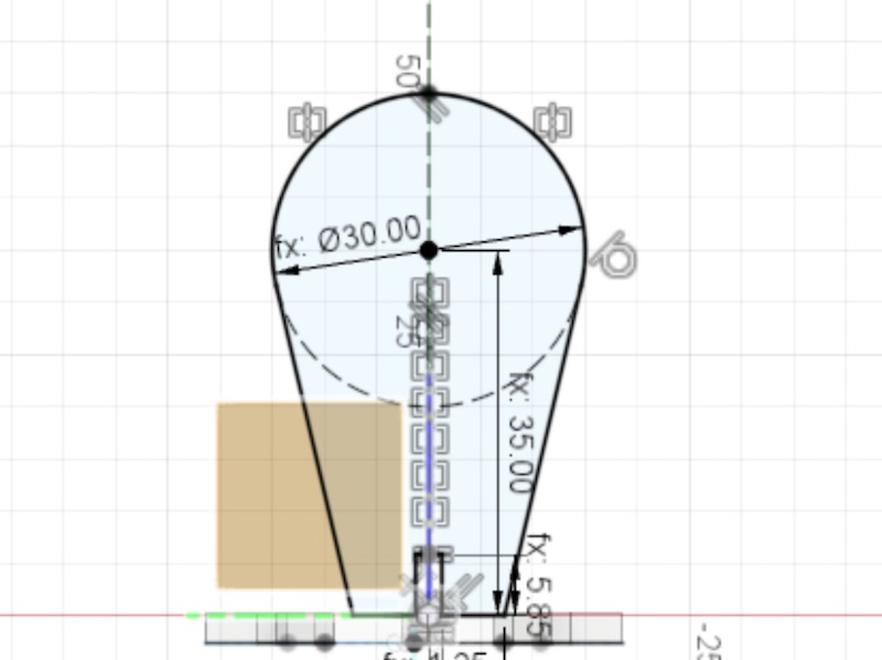
The petal has parameters for its length and width as well as the slot based on the material thickness. I was a bit concerned that it wouldn’t look organic enough if I just used a circle and straight tangent lines going back to a narrow base but it got something made quickly and I could always go back and increase the complexity of the shape later. The only tricky thing on the petal was making sure the base was narrow enough that petals wouldn’t intersect each other as the center circle got smaller. I chose a good base size and addressed this further in the connector design.
Petal Connector
I designed a small connector to fit into the slot in the center circle and have another slot for a petal. I wanted these parts to be as small as possible to not distract from the overall shape of the flower. I also wanted them to be curvy and organic rather than mechanical and straight edged. I probably could have done these faster that way and added the curves later and I may still go back to that if I take a second pass at these designs. I’m still learning how to fully constrain a sketch and I was thrown for a loop a few times when defining the aesthetic curves for these parts. I was able to use parameters for the size of the slots and the angle between the two slots but I still haven’t fully constrained this sketch. I lost my sense of scale a bit when designing these parts and added in some 0.5mm radius chamfers which you can barely tell when their cut as the full part is less than 20mm square. The other flaw in this design is that the outer sides of the slots are very thin and especially in cardboard they’re fragile. They work but probably won’t survive many rebuilds.
Once I got a connector and a petal modeled I repeated the bodies around the center circle to see if the petals collided with each other and they did pretty badly. Instead of just making the petals thinner I decided to make a second version of the connector that held the petals a bit lower below the circle. This way I could alternate short and tall connectors and the petals would not intersect. I also lowered the angle that the petals are mounted. This gives more options for construction. Once I had this connector I modeled the full set of petals and connectors and the intersections looked clear so it was time to start cutting.
Cutting
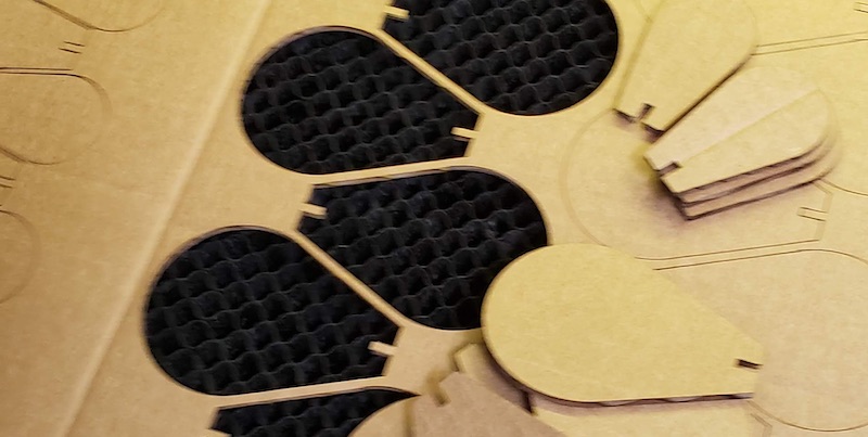
I exported the .dxf files for each of my shapes and brought them into Lightburn to cut them. I cut a test of each of the 4 shapes and fit them together. They worked great so I cut a few more connectors and petals to make a single flower.
I then wanted to take advantage of the parametric design and make a few more shape options. I changed the parameters for the center circle diameter and the petal length and width and exported .dxf’s for a larger center and a smaller petal. I used Lightburn’s grid pattern tool to tesselate each shape to be more efficient with materials usage and cut a bunch of each shape.
Flower Arrangements
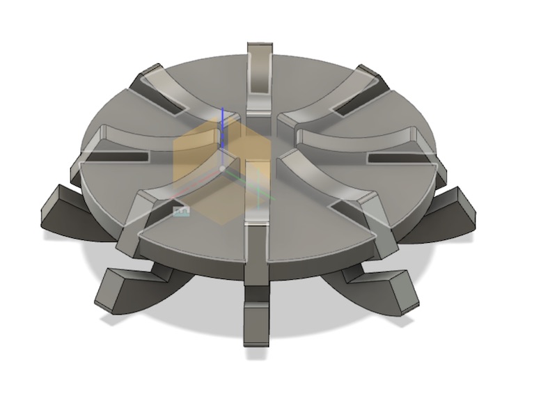
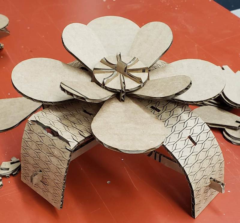
Now that I had some flowers I returned to the idea of how you would group multiple flowers into an arrangement. I started by making some simple rectangular stems. I just drew a rectangle in Lightburn and read off the measurements from my Fusion file for a quick test. I’m still formulating my idea of what these stems will attach to but tried a quick experiment using some living hinge patterns I found on Instructables. My first idea was to make a dome out of a series of arcs that had a common center point at different angles. When I tried to put a flower on it the arc couldn’t support the weight. I’ll keep thinking about ideas for that.
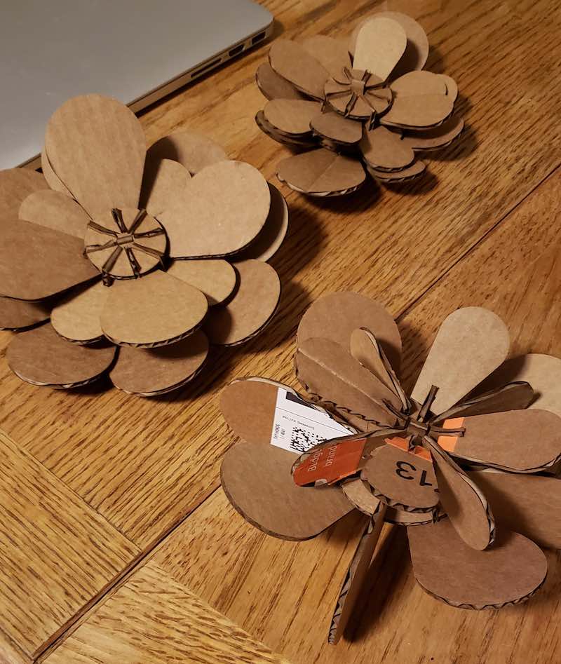
Testing the Kit
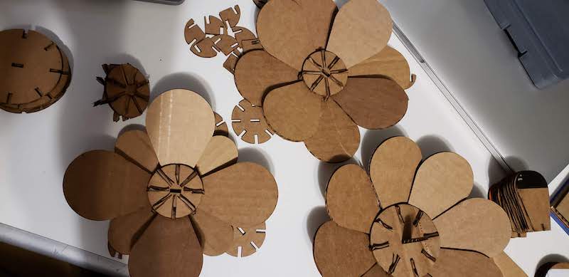
When I brought home the parts I had made so far I assembled a few different flowers and gave them to my housemates to play with. I found the best looking variations involved stacking 2 centers on the same stem to give the flower even more depth. I also played with skipping the connectors and attaching the petals directly to the centers and installing the connectors in ways I hadn’t originally intended. This definitely creates some interesting “flowers”. I’m declaring success on this project for now. I may add a flower pot or some other way to put multiple stems into a group but this is good for now.
Design Files
Use Your Own Parameters
To make your own version of these flower and take advantage of the parametric design you can use the Fusion 360 file here.
Flower Kit Fusion source file
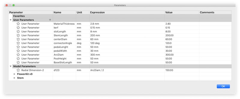
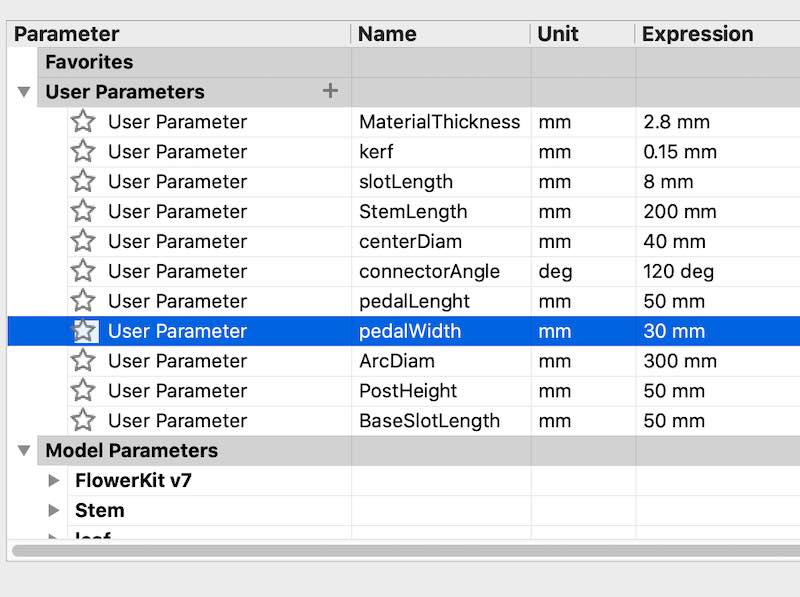
The parameter table for the design above will allow you to create these flowers in any material by adjusting the MaterialThickness and kerf parameters. The shapes will automatically adjust as those parameters are changed. The advantages of this over traditional CAD design is clear because in my process above I designed the center of the flower once and the petal of the flower once and then adjusted a single parameter to create a larger center and a smaller petal. You could use these to remake these same creations in something like 3/4" plywood simply by scaling up these parameters and sending the cut files to a CNC router instead of a laser.
Or Use Mine
Or if you just want to cut my version of the flowers use the DXF files here.
Flower Kit Cut Files