Circuit Board Milling
Assembling the Genmitsu 3018-PRO
The instructions were ok but not great. I had 3 hiccups in my assembly.
First was assembling the bearing blocks onto the bottom of the build plate. The plastic blocks are asymmetrical. The bolt holes are closer to one side than the other. It probably doesn’t matter but getting everything matching as well as possible left to right and front to back will hopefully keep this machine as flat and square as possible. I ended up removing one and flipping it around once i noticed.
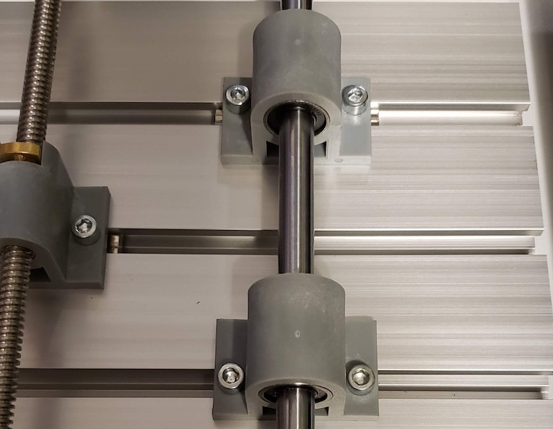
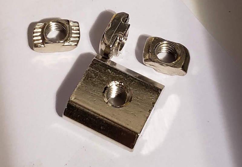
The second hiccup was the T-nuts. They’re awful. I also didn’t notice until after I had fully installed the bed that there were larger T-nuts that were intended for those slots rather than the small ones that fit the frame. One of these things is not like the other, but when the bolts are all the same size and I had already used the smaller t-nuts so didn’t notice that there were bigger ones until I needed more small ones and didn’t have enough. I had to loosen all of the small ones off and replace them with the correct size.
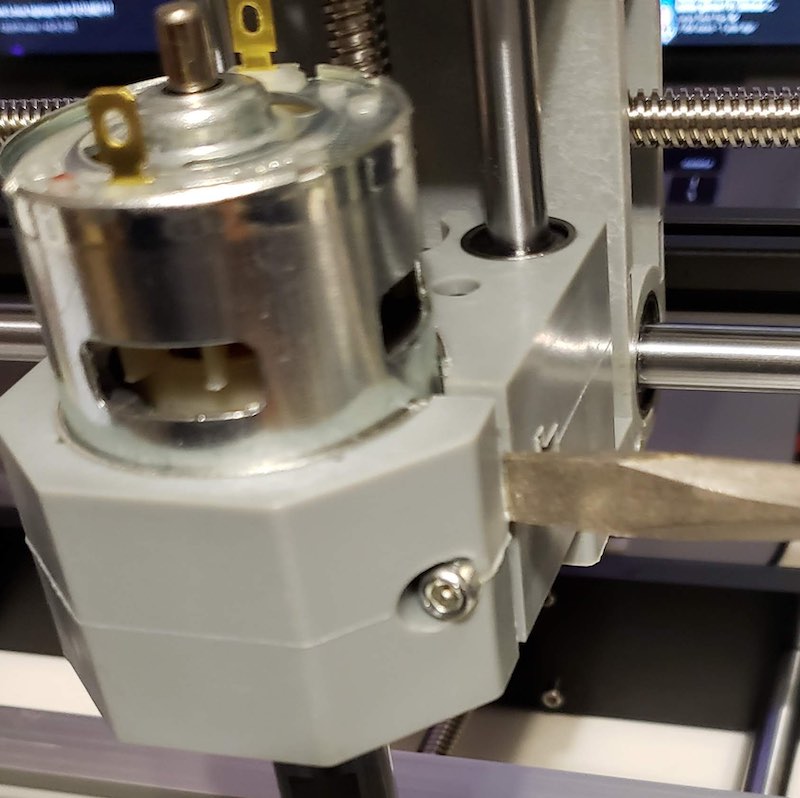
Lastly installing the spindle I had to use a flat head screwdriver to pry open the plastic holder to get the spindle to slot in.
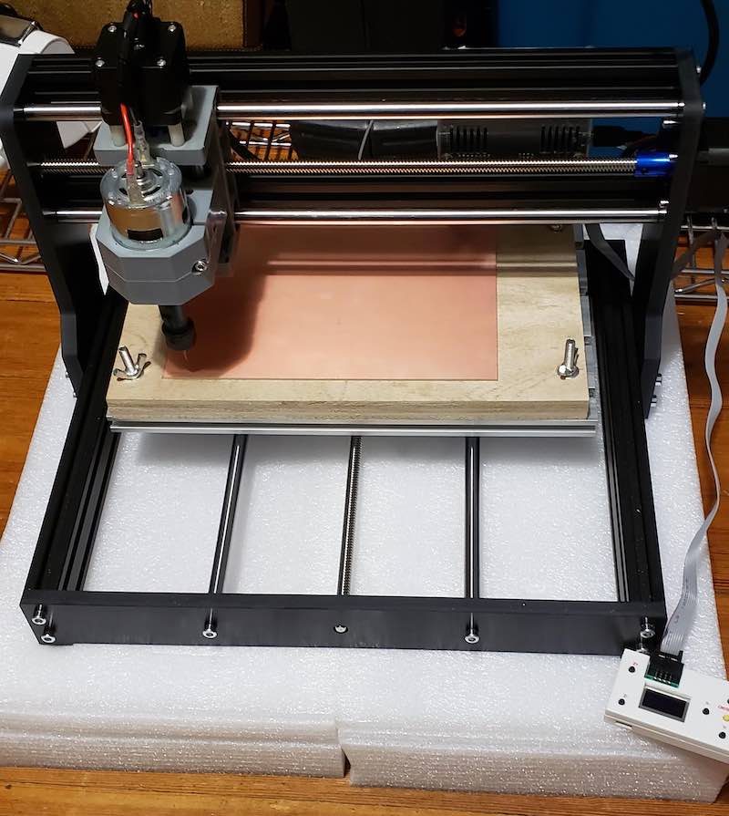
Next I needed to get a spoil board so that I don’t cut into the aluminum bed and probably instantly break all my bits. I cut a piece of scrap 3/4 inch plywood to approximately the same size as the bed. I placed it over the bed and marked a hole over the slots in the corners. I used the included hold down hardware to just bolt that right to the bed. I played around with loosening and tightening the frame bolts to get it as flat as possible and decided it was close enough. After my first cut I decided I needed a vibration dampener so I used the packing foam that the mill came in to create a platform.
CAM Toolchain
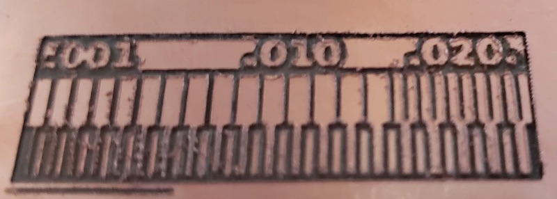
I started with the test pattern provided in the lecture to make sure the mill was working properly.
Mods, Generating G-code
Open Program
G-code
mill 2D PCB
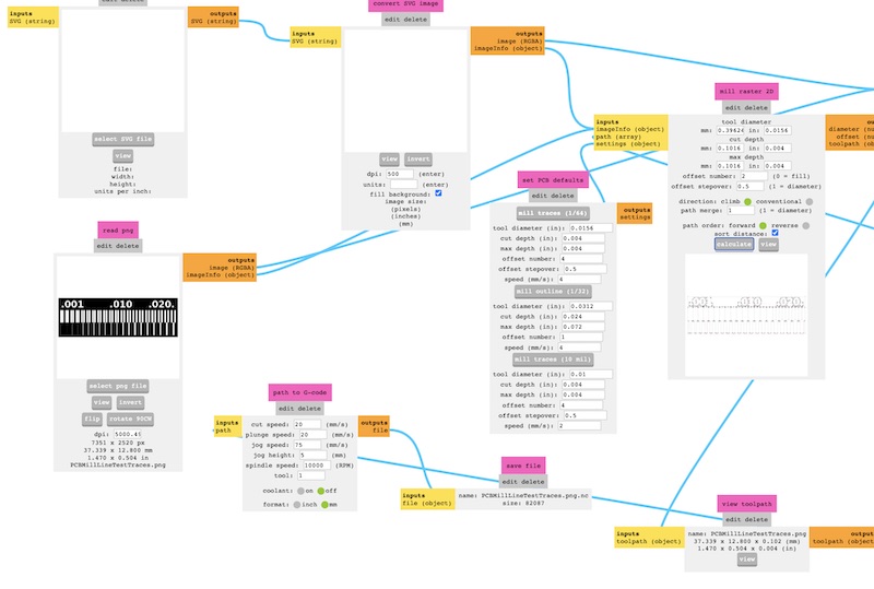
The one thing i keep getting wrong in mods is that right click activates the menu and left click pans around the environment. I wonder if there’s an easy way to switch that.
In the read png module select the traces image file. Double check the dpi settings and read out the dimensions to make sure they are correct. Adjust the dpi as needed to scale the png correctly.
In set PCB defaults choose the bit size and the corresponding settings they will populate into mill raster2D. or enter custom settings directly in the mill raster2D module. tool diameter, cut depth, and max depth are self explanatory. offset number is the number of passes around the traces to clear out excess copper to reduce bridging traces while soldering. offset stepover sets how much overlap between each of those passes. direction climb or conventional sets the direction of movement in relation to the rotation of the cutting bit. I haven’t tried path order or sort distance. Path order seems obvious. I’m not sure what sort distance does. I asked during our local section if there was documentation for all of these settings and was told that Neil would have thought they were all perfectly clear and so didn’t need documentation, but as we’ve been told Neil thinks a bit differently than most of us so we’re on our own. Good luck friends.
Next adjust the settings in path to G-code. I found that turning up the cut and plunge speed lead to breaking bits so stick with the default 20mm/s for now. I cranked up the jog speed to 150mm/s and jog height to 1mm to speed things up. Turn coolant off, we don’t have that on the 3018. Set format to mm.
I’m not sure if its a limit of the 3018 or something about the universal G-code sender but if you click edit on the g-code module and remove this line.
str += "T"+tool+"M06\n" // tool selection, tool change
This will prevent having to remove the “T1M06” line from the gcode file manually later.
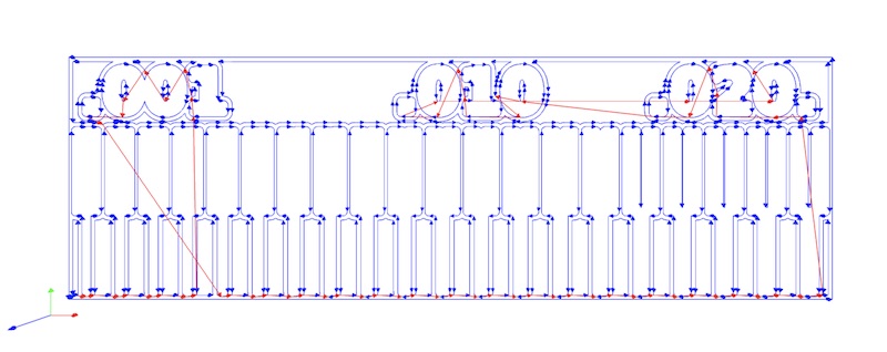
After all the settings are input click calculate in the mill raster2D module. This will download a .nc file which is just gcode. It will also show a preview of the cut path in the browser.
Universal G-Code Sender
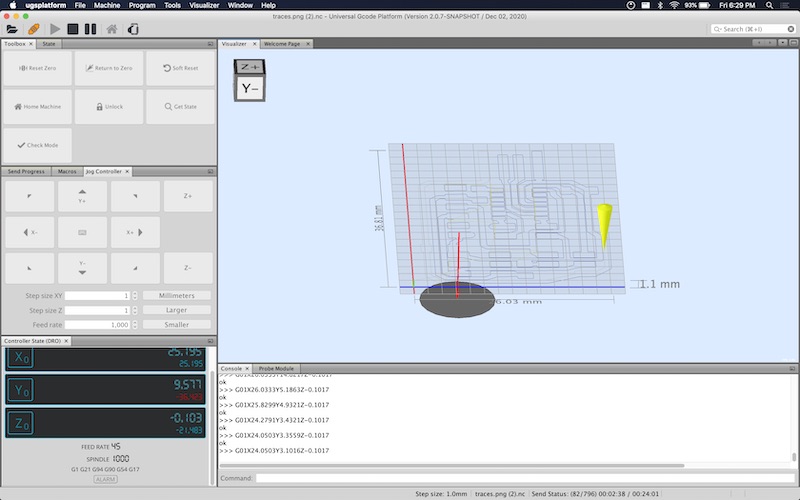
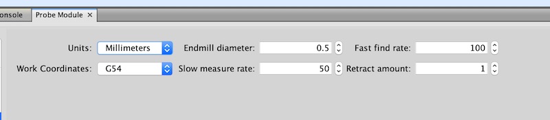
Open the .nc gcode file in universal gcode sender. First, set the origin for where to start the cut. Use the jog commands to move the x and y axis into place. Press X0 and Y0 in the controller state DRO panel. There are multiple ways to set the z axis zero. The simple way is to set the z axis step size to 0.1mm, place a sheet of paper on top of the work piece. Lower the bit while sliding the paper back and forth until the paper is just barely trapped. Then hit the Z0 button. The faster way is to make a z probe. I used a F-F jumper wire and an alligator clip lead. Cut each of them in half and solder the halves together. Plug them into the A5 headers on the control board. Then clip one of them to the bit and the other to the board. In UGS go to Window -> Plugins -> Probe Module. In the Probe Module settings reduce the end mill diameter, fast find rate , slow measure rate. If the find rates are too fast the bits may break upon impact with the surface. Go the to Z tab in the probe module and set the touch plate thickness. Use 0 if touching off directly on the copper plate. Click Initiate Probe when you are over the work piece and it will automatically lower the bit until it makes contact and set the z axis zero there. Then hit the play button and run the job.
Cuts
Note all of the below settings claim speeds in mm/s. These speeds are actually in mm/min and are mislabeled in the community edition of mods. This bug has already been fixed in the CBA edition of mods, but I didn’t know any of this until a week after these cuts were made.
Cut 1: Test Pattern
My First cuts were using the Test pattern above and the default settings in mods other than using only 1 offset to decrease cut time. I used a V bit in the mill as our instructors told us they were less likely to break but not cut as cleanly. I setup my first cut and as soon as it started cutting it looked like nothing was happening after the initial plunge but I realized the double sided tape holding down the FR1 had broken free. I stopped the cut, added more tape and reset. I restarted the cut and let it go for a few minutes but decided that the machine was so loud and causing a lot of vibration through the floor that I should wait until it wasn’t late at night to run this cut. I used the foam that the mill was packaged in to create a vibration damping platform for the rest of my cuts.
Cut 2: Test Pattern Take 2
The next morning I reran the previous cut successfully. The foam reduced the vibration noise to an acceptable level although I still wore earplugs when I was in the same room with it. The cut was slow taking about an hour and the edges were fairly ragged but it worked.
Cut 3: Faster Faster Faster
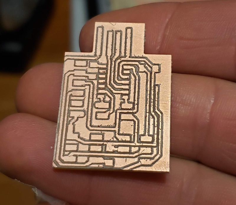
I was impatient after the first cut and wanted to increase the speed and cut an actual board. I used the traces file for the SAMD11C14 UART/UPDI programmer. I switched to the 1/64 end mill and cranked up the cut rate to 45mm/s and plunge 30mm/s which Spencer suggested as workable settings for the V bit. I was ambitious and tried to use those settings with the cheap end mill. It broke as soon as it touched the workpiece.
Cut 4: Back to the V Bit
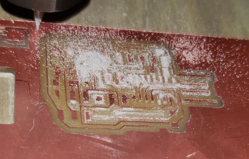
I then went back to the V bit because I wanted to see a finished board even if the V bit gave a lower quality cut. This is faster than the previous successful cut but still quite slow. It took about an hour to cut the traces. This was still with only 1 offset pass so the board probably wouldn’t be usable but I could practice soldering on it while the next one cut. When the cut finished I was setting up to switch bits to cut the outline of the board and instead of hitting return to zero I hit reset zero which lost my origin.
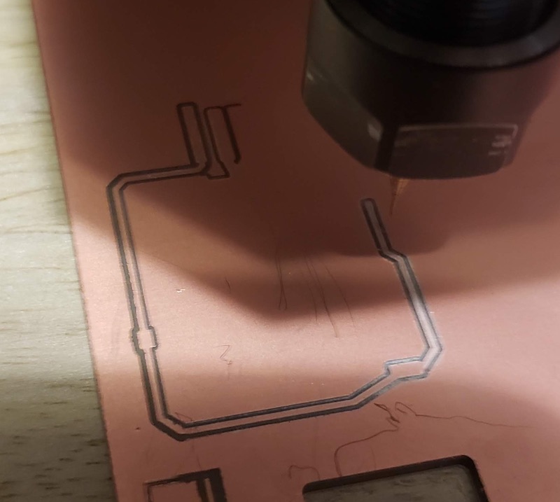
Cut 5: Lost in Space
With the origin of the last cut lost I did my best to guess where it was. I installed the 1/32 end mill and zeroed the z axis. I used mods to generate the gcode with the interior png file from the above link with the preset settings for the 1/32 bit to cut outlines and slowed it back down to 20mm/s cut and plunge rate. First thing I noticed was that this end mill is so much quieter than the V bit. The end mill stayed intact which was a good sign. The cut worked great but my guess for the location of the origin was a bit off so the left most trace on the board got cut off, but as I said this wasn’t going to be a finished board anyway. This proved out the settings for the 1/32 end mill.
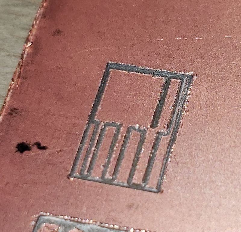
Cut 6: Search for End Mill Settings

I made a smaller version of the test pattern to try to run some test settings with the 1/64 end mill. Now I don’t want to use the V bits anymore after hearing how much quieter the end mill was. I turned the speeds back down to 20 mm/s cut and plunge rate. Setting up the cut I broke another 1/64 end mill running the z probe. I turned down the fast find speed in the z probe settings to not repeat that. I loaded up another bit and started the cut. This cut worked fine.
Cut 7: End Mill Graveyard
Now that I had end mill settings that worked I turned up the offset number to 4 to create a usable board with more clearance around the traces. It ran for about 10 minutes and then the bit snapped. My end mill graveyard is now population 3.
Cut 8: Calling in the Big Guns
My home lab kit has 10 cheaper 1/64 bits and 2 higher quality 1/64 bits. The cheap ones have a very long shank on the cutting portion of the end mill. The higher quality ones have much less shank for side cutting but that will make them stronger. Keeping the origin from the previous cut I installed the new bit and zeroed it and repeated the same cut. It cut through the channel left by the previous cut and then resumed cutting where the last bit broke. This cut was deceptive because as it repeated the offsets there were a few places where it wasn’t actually cutting anything so it went quiet. I was worried that the bit had broken but it was hard to tell visually because the stick out is so small. It kept cutting a few seconds later. This cut finished successfully but it took 2 hours.
Cut 9: Again, Not Faster
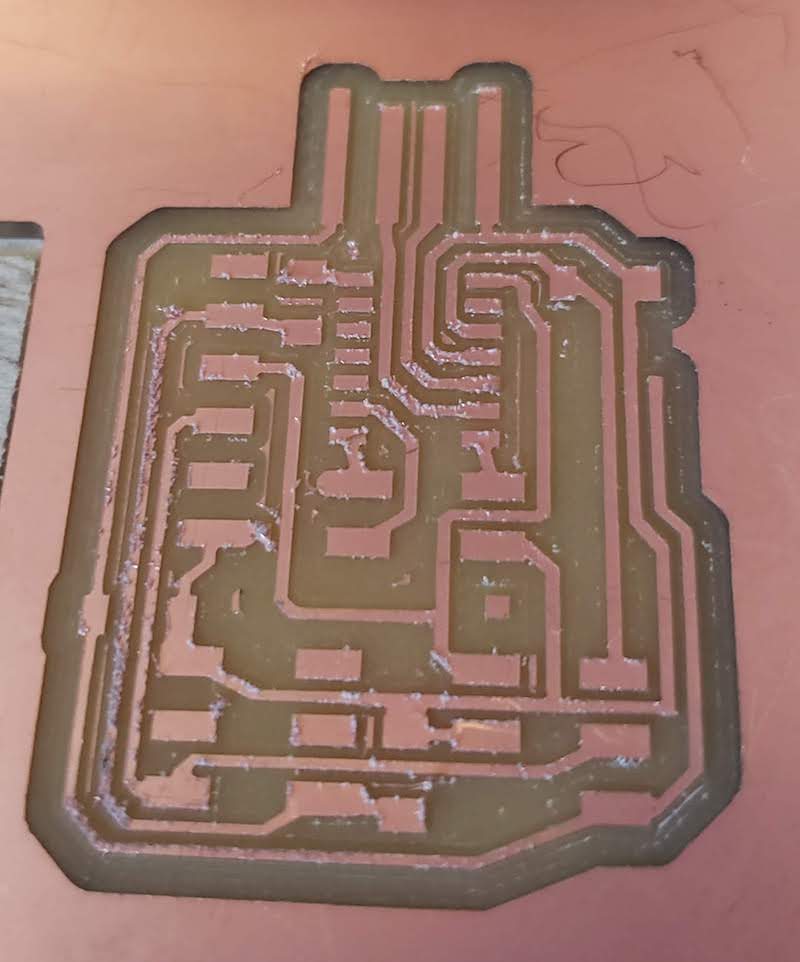
I repeated the same setup from cut 5. 1/32 end mill at 20mm/s cut and plunge and cut the outline of the board. This worked just as before but this time I had saved my origin and had a successful board. This isn’t fast but I had some snow to shovel while it cut.
Need for Speed (added 2/28/21)
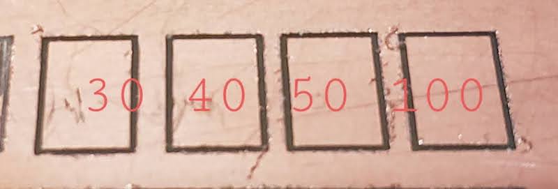
All of these cuts worked but were way too slow. After completing the rest of the assignment I went back to see if I could turn up the speed and get similar results. I was using the same end mill as is normally used in the lab on the Roland mill and I’m told this board should be able to be cut in about 20 minutes. There had to be something wrong with my setup. First I went back to my test pattern which had a 30mm outline and ran a cut at the previous setting, 20mm/s or so I thought. It took 2 minutes to cut 30mm. 0.25mm/s Much slower than expected. Then I started editing the Gcode manually and turning up the speed. If the Roland could use this bit faster and I had one working board then I was going to turn up the speed until I got something faster or the bit broke. I opened the g-code in a text file and edited the feed rate F command in gcode for everything that wasn’t a plunge command. I repeated the cut with speed at 100, 200, 500, 300. As I turned up the speed I also experimented with reducing the cut depth. The default cut depth was 0.1mm so I tried to cut that in half to 0.05mm. After each cut I tested the continuity between the cut outline and the rest of the board and it was not connected so this reduced depth of cut was sufficient as long as my machine stayed flat. Getting back to the speed, 500 was too fast there was a lot of chatter and it didn’t cut all the way through, but the rest were ok. After doing this gcode editing I wanted to look more into the grbl defaults and gcode settings for speed. I found that the speed setting G94 tells the machine to interpret the speed as Units per minute and the G21 sets those units to mm. G20 would set it to inches. This meant that when I though I was setting the speed to 20mm/s it was actually 20mm/min. Now that I knew the speeds were all wonky I setup another round of test cuts.
I also did some digging into mods to see that it set G94 and G21 in the gcode generation module. I checked the CBA edition of mods which has different defaults in this same program. The default speed is 2.5mm/s instead of 20, and when I looked at the code in gitlab it had been updated to note this error and modified accordingly. I’ll submit a bug to the community edition of mods.
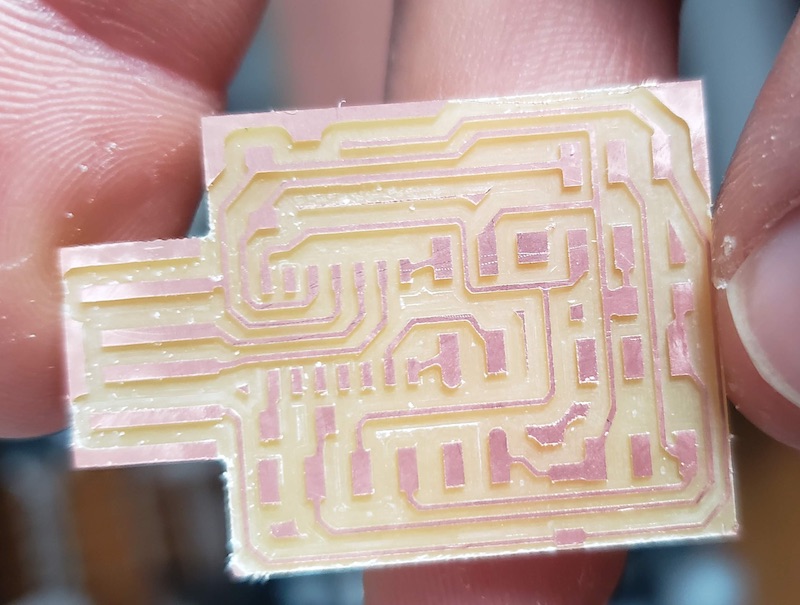
After finding all of this I wanted to cut another board faster. I got ambitious and cranked the speed up to 180mm/min since I had up to 300 working in my tests, and I noted that the default in mods in the set PCB defaults module was 4mm/s which was overridden by the faulty gcode module. I went with 180mm/min which is 3mm/s. This worked for 2-3minutes of cutting and the bit broke. I then turned the speed down to 100mm/min and restarted the cut. This worked fine and cut the same board that took me 2 hours last week in 20 mins. I’m glad to have more reasonable cut times now though I did sacrifice one of my two high quality end mills.
This cut isn’t as clean but its 5 times faster so I’ll take it. I will probably go down to 80mm/min for my next board to try to get slightly cleaner edges on the traces but the results from this board are good enough.
Stuffing the Board
I have a lot of experience soldering wires and through hole components but I have not had much success with surface mount soldering. I had planned to use my first test board to practice and then move on to the good board. I got impatient and just went for it.
Picking Components
One problem with the documentation of this programmer is it doesn’t have a part list. Most of the components are discusses in the write up but it took me a while to be confident that I had all the right parts. If I hadn’t been given a limited selection of parts in my home lab kit I would not have been able to order the parts I needed based on this page. I also didn’t have the right headers so I modified some parts from the through hole headers I was given.
| Part | Quantity | Substitue? |
|---|---|---|
| ATSAMD11C14 | 1 | - |
| 1.2kΩ Resistor | 1 | 1kΩ Resistor |
| 4.7kΩ Resistor | 1 | 5kΩ Resistor |
| 1μF Capacitor | 2 | - |
| 3.3v 100mA linear regulator sot23-3 | 1 | - |
| SMD right angle headers 6 POS | 1 | - |
| SMD headers 2x2 | 1 | modified through hole headers |
| SMD headers 2x3 | 2 | modified through hole headers |
| Header jumper | 2 | modified through hole socket headers |
I also went through the resistor kit and relabeled all of them using this site to translate the resistor codes into actual values.
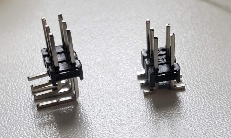
We didn’t get upright SMD headers in our kit so I modified some right angle through hole headers by flipping one of the pins around and clipping them shorter with some diagonal cutters.
Soldering
Flux Core Solder
Greg warned us that the solder in our kits was not flux core and was harder to solder with. I tried to use it for making my Z probe noted above and I found it unusable. I had some old Rosin core solder and used that for all of my soldering. It worked much better.
Surface Mount
I started with one of the capacitors as they were a larger component as surface mount pieces go. I used the suggestion from Duaa’s lesson from bootcamp to tin the first pad and the place the component onto that.
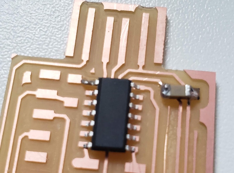
It took some practice with the tweezers to get components flat onto the board on that first pad. Once it was held down it was pretty easy to get the rest of the pins soldered. Luciano also had a good suggestion to use a bit of double sided tape to stick the board to the table. He also suggested repositioning the board often. I thought of it like welding. you get the best results by getting yourself into the most comfortable and stable position. The one thing I didn’t like about my setup is that my desk is so full of stuff that I was working right on the edge so didn’t have a lot of space to rest my hands. I managed to bridge a few traces but was able to recover them.
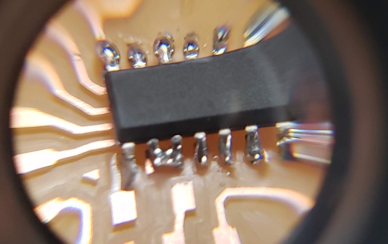
I tried to use the solder wick included in our kit but couldn’t get it to do anything. The solder sucker worked great at picking up excess solder. The key was just being patient and letting the parts and pads heat up. Once the solder on the iron started to flow onto the parts I added a bit more and it was good. I could tell if I wasn’t getting enough heat into the parts if when I moved the iron away the solder wanted to stick to it.
Smoke Test
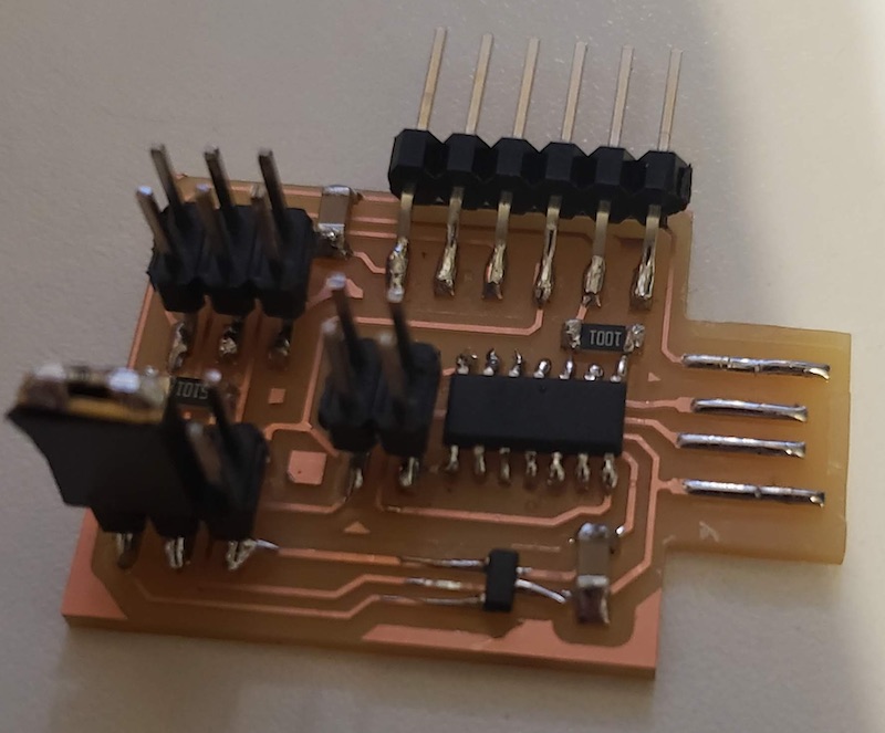
I plugged in the USB port on the board to a 5V DC supply to see if I passed a smoke test. I saw a little wisp of smoke so unplugged it. I couldn’t figure out where it was coming from so I plugged it in again and touched the regulator as that seemed a likely culprit. It was so hot that it de soldered itself and moved on the board. I pulled the plug and checked the schematic. I reviewed the documentation and found I had installed the relay backwards. I used the technique suggested by holding the board with tweezers by the broken regulator and using a hot air gun to melt the solder holding in on. I got a new component and cleaned up the solder pads and installed it the correct way. I then plugged it in and used my multimeter to test the voltages from either side of the regulator. That looked good. Now I need a JTAG programmer to test the board further. I might need to go into the lab to get that.